EP0836364B1 - Hearing aid - Google Patents
Hearing aid Download PDFInfo
- Publication number
- EP0836364B1 EP0836364B1 EP19970116809 EP97116809A EP0836364B1 EP 0836364 B1 EP0836364 B1 EP 0836364B1 EP 19970116809 EP19970116809 EP 19970116809 EP 97116809 A EP97116809 A EP 97116809A EP 0836364 B1 EP0836364 B1 EP 0836364B1
- Authority
- EP
- European Patent Office
- Prior art keywords
- sound
- hearing aid
- guide structure
- tubes
- ear
- Prior art date
- Legal status (The legal status is an assumption and is not a legal conclusion. Google has not performed a legal analysis and makes no representation as to the accuracy of the status listed.)
- Expired - Lifetime
Links
Images


Classifications
-
- H—ELECTRICITY
- H04—ELECTRIC COMMUNICATION TECHNIQUE
- H04R—LOUDSPEAKERS, MICROPHONES, GRAMOPHONE PICK-UPS OR LIKE ACOUSTIC ELECTROMECHANICAL TRANSDUCERS; DEAF-AID SETS; PUBLIC ADDRESS SYSTEMS
- H04R25/00—Deaf-aid sets, i.e. electro-acoustic or electro-mechanical hearing aids; Electric tinnitus maskers providing an auditory perception
- H04R25/65—Housing parts, e.g. shells, tips or moulds, or their manufacture
-
- H—ELECTRICITY
- H04—ELECTRIC COMMUNICATION TECHNIQUE
- H04R—LOUDSPEAKERS, MICROPHONES, GRAMOPHONE PICK-UPS OR LIKE ACOUSTIC ELECTROMECHANICAL TRANSDUCERS; DEAF-AID SETS; PUBLIC ADDRESS SYSTEMS
- H04R25/00—Deaf-aid sets, i.e. electro-acoustic or electro-mechanical hearing aids; Electric tinnitus maskers providing an auditory perception
- H04R25/45—Prevention of acoustic reaction, i.e. acoustic oscillatory feedback
- H04R25/456—Prevention of acoustic reaction, i.e. acoustic oscillatory feedback mechanically
-
- H—ELECTRICITY
- H04—ELECTRIC COMMUNICATION TECHNIQUE
- H04R—LOUDSPEAKERS, MICROPHONES, GRAMOPHONE PICK-UPS OR LIKE ACOUSTIC ELECTROMECHANICAL TRANSDUCERS; DEAF-AID SETS; PUBLIC ADDRESS SYSTEMS
- H04R2460/00—Details of hearing devices, i.e. of ear- or headphones covered by H04R1/10 or H04R5/033 but not provided for in any of their subgroups, or of hearing aids covered by H04R25/00 but not provided for in any of its subgroups
- H04R2460/09—Non-occlusive ear tips, i.e. leaving the ear canal open, for both custom and non-custom tips
Definitions
- the invention relates to a hearing aid in accordance with the preamble of claim 1.
- Such equipment which has become known as hearing aid with open adaptation, consists generally of a device worn behind the ear with a sound tube extending into the ear lobe or the auditory canal without tightly closing the auditory canal.
- Such adaptations are possible of course only with minimal amplification and a totally linear frequency characteristic since otherwise, feed back coupling with fringe haul would be unavoidable.
- Cross-hearing aid Another open adaptation which is only rarely used is the so-called “Cros-hearing aid” which is always separated into two parts of which the microphone is worn at one side of the head and the ear piece or sound emitter at the other.
- This type of hearing aid is generally used only if the sensitivity of the two ears of a person with hearing defects is very different. Such devices are not subject to feed back coupling because there is a relatively large distance between the microphone and the ear piece.
- the auditory canal is practically fully closed by the ear piece whose sound discharge opening is in the interior of the auditory canal.
- the microphone of such a hearing aid is in communication with a sound entrance opening at an exposed outer side of a housing of such a hearing aid. The tight fit of such a hearing aid in the ear of a user prevents feed back coupling.
- a disadvantage of the normal hearing aid is further that, in order to prevent feed back coupling and acute fringe haul, the ear is closed (sealed).
- the transmission range toward higher frequencies is not good and there are problems in determining the direction from which a sound is coming.
- hearing aids do not have a good image. For this reason, hearing aids are often not used even if a person would really need to wear one.
- the state-of-the-art for the correction of this kind of hearing losses includes the so-called high sound frequency hearing aids.
- These are hearing aids which amplify only the higher sound frequencies, whereas the lower frequencies are not amplified. But even these hearing aids can hardly be used by the group of people referred to above.
- the amplification of sounds of 1 kHz and higher is quite high so that the hearing aid has feed back coupling tendencies.
- a tight ear shell is generally used which, however, is somewhat awkward to wear.
- the reproduction quality and the sound localization capabilities are limited.
- these hearing aids are almost always custom made and, consequently, expensive.
- the auditory canal is tightly closed which prevents normal hearing in the low frequency sound range.
- EP0455203 describes a hearing aid comprising a dual-outlet receiver transducer connected to an amplifier whereas the receiver comprises a diaphragm mounted within the housing and defining a first and second acoustic chamber in the receiver housing and an electromagnetic motor, mechanically connected to the diaphragm and first and second outlet ports of equal length, one for each acoustic chamber and first and second sound transmission tubes, each tube connecting its respective outlet port into the user's ear canal.
- the hearing aid Since the auditory canal is not closed by the hearing aid it is not necessary to fit the hearing aid into the ear so that it does not need to be custom-made whereby it can be manufactured at relatively low cost. Furthermore, the hearing aid can be designed as desired such that the device could be incorporated for example into earrings or another jewelry piece.
- the amplifier is a high frequency amplifier which amplifies only in the high sound frequency range, for ex-ample, from about 4 kHz by 10 to 20 dB.
- This can be determined for example by means of a filter associated with the amplifier for selecting the respective transmission frequencies.
- the sounds can be selectively amplified only in the high frequency range in a simple manner whereas, in the low frequency sound range, direct hearing by way of the open auditory canal is insured.
- a relatively simple sound guide arrangement is achieved which has a substantial directional effect with regard to the sound emission.
- the signals from the various tubes arrive at the same time at an axial point in front of the sound discharge openings and are added up provided that the sound speed in the tubes equals the sound speed in the air.
- the signals from the various tubes arrive with a phase shift and can therefore not be added up properly or, under advantageous conditions, cancel each other.
- the features of claim 3 have the advantage that such a sound guide arrangement can be manufactured in a relatively simple manner.
- an multi-chamber hose as it is known per se in medical technology is provided as a sound guide structure.
- the features of claim 5 provide for a large number of sound discharge openings.
- the fact that the sound pressure becomes smaller with the distance from the sound source that is the sound generator is accommodated by the wedge-like shape of the slot.
- Such a sound guide structure can be arranged for example in a simple manner at the frame of hearing glasses wherein the free end of the sound guide structure is directed toward the ear.
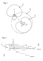
- Fig. 1 shows schematically a hearing aid according to the invention inserted into an ear.
- a hearing aid containing a microphone, an amplifier and a sound generator is supported on an earhook 1 behind the ear 2 of a user.
- the earhook 1 is hollow and a hose 3 is connected to the earhook 1 and leads to a connecting socket 4.
- Connected to this connecting socket 4 are several tubes or hoses 5 of different lengths such that their front end sound discharge openings are staggered in axial direction of the tubes or hoses 5.
- These tubes or hoses 5 form a sound guide structure 10 which provides a directional effect for the sound discharge in the direction of the longitudinal axis of the tubes or hoses 5.
- the tubes or hoses 5 extend into the auditory canal 6 of the user.
- the hearing aid is disposed in the frame 7 of hearing glasses 8.
- a sound guide structure 10' is attached to the sound generator 9.
- the sound guide structure 10' will be described in greater detail.
- the free front end of the sound guide structure 10 is directed toward the ear of the user which is not shown.
- the auditory canal remains open permitting normal hearing, particularly in the low sound frequency range, like with the arrangement according to Fig. 1.
- a directional orientation capability remains although in a limited way provided both ears are capable of hearing.
- the polar coordinate diagram of Fig. 3 shows in full lines the condition with a microphone-sound generator arrangement with a normal microphone 11 with directional characteristics and a sound generator 13 also with directional characteristics as it is used in the hearing aid according to the invention.
- kidney shaped sound level curves 12 of the microphone 11 and the also kidney-shaped sound level curve 14 of the sound generator 13 do not overlap so that there is little tendency for a feedback coupling of the arrangement.
- a microphone which is suitable for an ear phone and which has appropriate directional characteristics could be for example, a pressure gradient microphone.
- the sound level curve 12 of the microphone 11 would overlap the sound level curve 15 of a sound generator without directional characteristics so that the chances of feed back coupling would be very high with such an arrangement.
- loudspeakers with directional characteristics are well known for the purpose of acoustic irradiation.
- acoustic arrays are used where several single loudspeakers are arranged side-by side in a line so as to define a front for the sound wave generated thereby and, accordingly provide a directional effect.
- passive methods are known whereby with acoustic lenses the front of the wave and, consequently, the directional characteristics can also be controlled. In principle, all methods can be reduced to the following two processes. Firstly, several cooperating converters (at least two) are used. The second possibility is to use acoustic lenses or other passive means. For the application described herein a combination of the different methods may be used for price and space reasons.
- the main player herein is the loudspeaker (sound generator) where solutions for hearing aids with their given smallness are not common or rather not known up to now.
- the frequency range in which the directional effects of the sound generator is essential is relatively high and, consequently, the wave length is small.
- the required directional effect can be obtained also by passive solutions.
- FIG. 4 A possible arrangement for a directional sound generation for a hearing aid in accordance with the invention is shown in principle in Fig. 4. It includes a sound generator 9 with a sound discharge structure comprising several tubes 5. Each tube 5 has a different length. Seen in an axial direction (0°) and assuming that the sound speed within the tubes 5 is the same as in air, all the signals from the different tubes arrive at the point A at the same time and are added up. However, the signals arrive at point B with a phase shift with regard to each other. They are therefore improperly added up and, under favorable conditions, they even cancel each other. With a given delay, the phase shift is frequency dependent which also results in a frequency dependent directional characteristic. It is to be noted that, actually, the sound speed in the tubes is smaller than in air if the tube diameter is substantially smaller than the wave length.
- the frequency range of a hearing aid in which the sound should be amplified and in which a corresponding directional characteristic of the sound discharge of the sound generator 9 is required, is relatively narrow and can usually be kept smaller than 4 kHz, hardly any problems are experienced since a relatively small number of tubes or hoses 5 are sufficient. As a result, also the diameters of the tubes or hoses 5 remain in a size range in which they can be relatively easily manufactured.
- the socket 4 may be formed by a slip or shrinkable hose piece which interconnects the tubes or hoses 5 with the sound hose 3 which generally consists of a plastic hose having an inner diameter of 2 mm.
- a forward/backward ratio of about 15 dB could be reached at a frequency of about 3150 Hz.
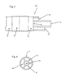
- Fig. 5 shows another embodiment of a sound guide structure 10" for a hearing aid according to the invention.
- a sound hose 3 is connected by way of a connecting socket 4, which may be a slip or shrinkable hose section, to a multi-chamber hose 31 having a cross-section as shown in Fig. 6.
- the chambers 32, 33 34, 35 have different length by a stepped cut.
- the chamber 32 has the shortest length whereas chamber 33 has a greater length, which is again exceeded by the length of chamber 34.
- the central chamber 35 has the greatest length.
- the absolute lengths of the chambers 32, 33, 34, 35 of the embodiments shown in Figs. 5 and 6 as well as the lengths of the tubes or hoses 5 of Fig. 4 are not critical. What is important is only the length difference between the shortest and the longest tube or hose 5 or respectively, the lengths difference between the shortest and the longest chambers 32 and 35.
- Fig. 7 shows another embodiment of a sound guide structure 10' for the hearing aid according to the invention. It includes a sound generator 9 connected to a tube 16 whose interior is filled with an open pore foamed material 17 which includes a wedge-shaped slot 18.
- the slot 18 is open at the free front end 19 of the tube 16 and there it has its greatest width. The slot 18 ends in front of the sound generator 9.
- This sound guide structure 10' includes an almost infinite number of discharge openings wherein the wedge-like form of the slot 18 takes into account that the sound pressure in the foamed material 17 as well as in all other media decreases with the distance from the sound generator.
- Fig. 8 shows a measuring arrangement for the polar diagrams of Figs. 9 - 11 by which the directional characteristics of the arrangement as shown in Fig. 4 were recorded.
- the arrangement is designated by the numeral 20.
- Sound is supplied to the tubes or hoses 5 by a sound generator 9 which is energized by way of an amplifier 21.
- the amplifier 21 receives its input signal from a frequency generator FG by way of an inductive system 27 in order to permit a rotation of the arrangement for recording the polar diagram.
- the sound is recorded by a measuring microphone 23. Note the different dB scales in Figs. 9 and 10.
- Fig. 11 shows the whole diagram in another representation (surface diagram).
Description
- The invention relates to a hearing aid in accordance with the preamble of
claim 1. - Such equipment which has become known as hearing aid with open adaptation, consists generally of a device worn behind the ear with a sound tube extending into the ear lobe or the auditory canal without tightly closing the auditory canal. Such adaptations are possible of course only with minimal amplification and a totally linear frequency characteristic since otherwise, feed back coupling with fringe haul would be unavoidable.
- Another open adaptation which is only rarely used is the so-called "Cros-hearing aid" which is always separated into two parts of which the microphone is worn at one side of the head and the ear piece or sound emitter at the other. This type of hearing aid is generally used only if the sensitivity of the two ears of a person with hearing defects is very different. Such devices are not subject to feed back coupling because there is a relatively large distance between the microphone and the ear piece.
- With the usual hearing aids such as those arranged in the outer ear or in the auditory canal, the auditory canal is practically fully closed by the ear piece whose sound discharge opening is in the interior of the auditory canal. The microphone of such a hearing aid is in communication with a sound entrance opening at an exposed outer side of a housing of such a hearing aid. The tight fit of such a hearing aid in the ear of a user prevents feed back coupling.
- If a person is exposed to loud noises for an extended period his or her ear may be damaged for some time or permanently. This may result in communication problems in special situations. Since the hearing loss so generated is usually not severe "normal" hearing aids with which the auditory canal of an ear is totally closed cannot be used or they are a nuisance. There is actually no suitable technical aid available for such persons.
- People with almost normal hearing usually have a hearing loss in the high frequency range (4-6 kHz) while their hearing is quite normal in the range up to 2 kHz. With a good signal-to-noise ratio such persons have no problems to understand. Problems arise only when it becomes noisy. Typical examples where problems with understanding would occur are for example visits in restaurants and coffee houses, on busy streets, when watching television, etc....
- A disadvantage of the normal hearing aid is further that, in order to prevent feed back coupling and acute fringe haul, the ear is closed (sealed). In addition, the transmission range toward higher frequencies is not good and there are problems in determining the direction from which a sound is coming. Also, hearing aids do not have a good image. For this reason, hearing aids are often not used even if a person would really need to wear one.
- The state-of-the-art for the correction of this kind of hearing losses includes the so-called high sound frequency hearing aids. These are hearing aids which amplify only the higher sound frequencies, whereas the lower frequencies are not amplified. But even these hearing aids can hardly be used by the group of people referred to above. Generally, the amplification of sounds of 1 kHz and higher is quite high so that the hearing aid has feed back coupling tendencies. To avoid this, a tight ear shell is generally used which, however, is somewhat awkward to wear. Furthermore, the reproduction quality and the sound localization capabilities are limited. Also these hearing aids are almost always custom made and, consequently, expensive. Finally, the auditory canal is tightly closed which prevents normal hearing in the low frequency sound range.
- For example, EP0455203 describes a hearing aid comprising a dual-outlet receiver transducer connected to an amplifier whereas the receiver comprises a diaphragm mounted within the housing and defining a first and second acoustic chamber in the receiver housing and an electromagnetic motor, mechanically connected to the diaphragm and first and second outlet ports of equal length, one for each acoustic chamber and first and second sound transmission tubes, each tube connecting its respective outlet port into the user's ear canal.
- It is the object of the invention to overcome these disadvantages and to provide a hearing aid of the type as referred to initially, which is particularly suitable to compensate for a hearing loss in the high frequency sound range.
- In accordance with the invention, this is achieved with a hearing aid of the type as described earlier by the features given in the characterizing part of
claim 1. - With the multitude of channels which, according to the invention, have sound discharge openings which are displaced relative to each other a directional sound effect is achieved in a simple manner such that the sound exits the essentially straight tubes or hoses essentially in an axial direction. As a result, there is no feed back coupling inspite of the fact that the auditory canal is not sealed off and the microphone is arranged close to the sound generator such that in the low frequency range normal hearing is possible.
- Since the auditory canal is not closed by the hearing aid it is not necessary to fit the hearing aid into the ear so that it does not need to be custom-made whereby it can be manufactured at relatively low cost. Furthermore, the hearing aid can be designed as desired such that the device could be incorporated for example into earrings or another jewelry piece. The hearing aid with microphone, amplifier and if applicable with filter for achieving a certain transmission function and the sound generator as they are commonly used with today's ear internal or auditory canal hearing aids, can be highly miniaturized.
- Preferably, the amplifier is a high frequency amplifier which amplifies only in the high sound frequency range, for ex-ample, from about 4 kHz by 10 to 20 dB. This can be determined for example by means of a filter associated with the amplifier for selecting the respective transmission frequencies. In this way, the sounds can be selectively amplified only in the high frequency range in a simple manner whereas, in the low frequency sound range, direct hearing by way of the open auditory canal is insured.
- With the features of
claim 2, a relatively simple sound guide arrangement is achieved which has a substantial directional effect with regard to the sound emission. With this sound guide arrangement, the signals from the various tubes arrive at the same time at an axial point in front of the sound discharge openings and are added up provided that the sound speed in the tubes equals the sound speed in the air. However, at a point behind the hearing aid, that is adjacent the microphone, the signals from the various tubes arrive with a phase shift and can therefore not be added up properly or, under advantageous conditions, cancel each other. As a result, there is no feedback coupling even if the distance between the microphone and the sound generator is relatively small since the sound level curves of the microphone and those of the sound generator which have suitably directional effects, are for example in the shape of a kidney and do practically not overlap. - The features of
claim 3 have the advantage that such a sound guide arrangement can be manufactured in a relatively simple manner. - In accordance with the features of
claim 4, an multi-chamber hose as it is known per se in medical technology is provided as a sound guide structure. - The features of
claim 5 provide for a large number of sound discharge openings. The fact that the sound pressure becomes smaller with the distance from the sound source that is the sound generator is accommodated by the wedge-like shape of the slot. - Such a sound guide structure can be arranged for example in a simple manner at the frame of hearing glasses wherein the free end of the sound guide structure is directed toward the ear.
- The invention will be explained below on the basis of the drawings wherein:
- Figs. 1 and 2 show schematically different embodiments of the hearing aid according to the invention,
- Fig. 3 shows schematically the sound level curves of a microphone-sound generator arrangement as it applies to a hearing aid according to the invention,
- Figs. 4 and 5 show various embodiments of sound guide structures,
- Fig. 6 shows a multi-chamber hose in cross-section,
- Fig. 7 shows another embodiment of a sound guide structure for a hearing aid according to the invention, and
- Fig. 8 shows a measuring arrangement by which the diagrams of Figs. 9 to 11 were recorded.
- Fig. 1 shows schematically a hearing aid according to the invention inserted into an ear. A hearing aid containing a microphone, an amplifier and a sound generator is supported on an
earhook 1 behind theear 2 of a user. Theearhook 1 is hollow and ahose 3 is connected to theearhook 1 and leads to a connectingsocket 4. Connected to this connectingsocket 4 are several tubes orhoses 5 of different lengths such that their front end sound discharge openings are staggered in axial direction of the tubes orhoses 5. These tubes orhoses 5 form asound guide structure 10 which provides a directional effect for the sound discharge in the direction of the longitudinal axis of the tubes orhoses 5. - The tubes or
hoses 5 extend into theauditory canal 6 of the user. - In the embodiment according to Fig. 2, the hearing aid is disposed in the
frame 7 ofhearing glasses 8. A sound guide structure 10' is attached to thesound generator 9. The sound guide structure 10' will be described in greater detail. The free front end of thesound guide structure 10 is directed toward the ear of the user which is not shown. As a result, the auditory canal remains open permitting normal hearing, particularly in the low sound frequency range, like with the arrangement according to Fig. 1. Also, at least in the low sound frequency range a directional orientation capability remains although in a limited way provided both ears are capable of hearing. - An essential problem with hearing aids by which the auditory canal is not closed resides in the possibility of feedback coupling between the sound generator and the microphone whereby the well-known fringe haul occurs. For this reason, the microphone and the sound generator are arranged in such hearing aids at a distance from one another wherein the known hearing aids utilize sound generators without directional effects.
- The polar coordinate diagram of Fig. 3 shows in full lines the condition with a microphone-sound generator arrangement with a
normal microphone 11 with directional characteristics and asound generator 13 also with directional characteristics as it is used in the hearing aid according to the invention. - As can be seen from Fig. 3, the kidney shaped sound level curves 12 of the
microphone 11 and the also kidney-shapedsound level curve 14 of thesound generator 13 do not overlap so that there is little tendency for a feedback coupling of the arrangement. A microphone which is suitable for an ear phone and which has appropriate directional characteristics could be for example, a pressure gradient microphone. - As shown by the dashed lines the
sound level curve 12 of themicrophone 11 would overlap thesound level curve 15 of a sound generator without directional characteristics so that the chances of feed back coupling would be very high with such an arrangement. - Also, loudspeakers with directional characteristics are well known for the purpose of acoustic irradiation. For this purpose acoustic arrays are used where several single loudspeakers are arranged side-by side in a line so as to define a front for the sound wave generated thereby and, accordingly provide a directional effect. Furthermore, also some passive methods are known whereby with acoustic lenses the front of the wave and, consequently, the directional characteristics can also be controlled. In principle, all methods can be reduced to the following two processes. Firstly, several cooperating converters (at least two) are used. The second possibility is to use acoustic lenses or other passive means. For the application described herein a combination of the different methods may be used for price and space reasons. The main player herein is the loudspeaker (sound generator) where solutions for hearing aids with their given smallness are not common or rather not known up to now.
- With hearing aids according to the invention, the frequency range in which the directional effects of the sound generator is essential is relatively high and, consequently, the wave length is small. As a result, the required directional effect can be obtained also by passive solutions.
- A possible arrangement for a directional sound generation for a hearing aid in accordance with the invention is shown in principle in Fig. 4. It includes a
sound generator 9 with a sound discharge structure comprisingseveral tubes 5. Eachtube 5 has a different length. Seen in an axial direction (0°) and assuming that the sound speed within thetubes 5 is the same as in air, all the signals from the different tubes arrive at the point A at the same time and are added up. However, the signals arrive at point B with a phase shift with regard to each other. They are therefore improperly added up and, under favorable conditions, they even cancel each other. With a given delay, the phase shift is frequency dependent which also results in a frequency dependent directional characteristic. It is to be noted that, actually, the sound speed in the tubes is smaller than in air if the tube diameter is substantially smaller than the wave length. - Since the frequency range of a hearing aid, in which the sound should be amplified and in which a corresponding directional characteristic of the sound discharge of the
sound generator 9 is required, is relatively narrow and can usually be kept smaller than 4 kHz, hardly any problems are experienced since a relatively small number of tubes orhoses 5 are sufficient. As a result, also the diameters of the tubes orhoses 5 remain in a size range in which they can be relatively easily manufactured. - As explained already on the basis of Fig. 1, it is not absolutely necessary to connect the tubes or
hoses 5 of different lengths directly to thesound generator 9. It is possible to connect to the sound generator 9 asound hose 3 in the usual way and to connect the tubes orhoses 5 to the end of thesound hose 3 by means of a connectingsocket 4. Thesocket 4 may be formed by a slip or shrinkable hose piece which interconnects the tubes orhoses 5 with thesound hose 3 which generally consists of a plastic hose having an inner diameter of 2 mm. - With such a sound guide structure with seven tubes or
hoses 5 and a difference in length between the shortest and the longest tube orhose 5 of about 20 mm, a forward/backward ratio of about 15 dB could be reached at a frequency of about 3150 Hz. - Fig. 5 shows another embodiment of a
sound guide structure 10" for a hearing aid according to the invention. In this embodiment, asound hose 3 is connected by way of a connectingsocket 4, which may be a slip or shrinkable hose section, to amulti-chamber hose 31 having a cross-section as shown in Fig. 6. Herein thechambers - As shown in Fig. 5, the
chamber 32 has the shortest length whereaschamber 33 has a greater length, which is again exceeded by the length ofchamber 34. Thecentral chamber 35 has the greatest length. - Basically, the absolute lengths of the
chambers hoses 5 of Fig. 4 are not critical. What is important is only the length difference between the shortest and the longest tube orhose 5 or respectively, the lengths difference between the shortest and thelongest chambers - Fig. 7 shows another embodiment of a sound guide structure 10' for the hearing aid according to the invention. It includes a
sound generator 9 connected to atube 16 whose interior is filled with an open pore foamedmaterial 17 which includes a wedge-shapedslot 18. Theslot 18 is open at the freefront end 19 of thetube 16 and there it has its greatest width. Theslot 18 ends in front of thesound generator 9. - This sound guide structure 10' includes an almost infinite number of discharge openings wherein the wedge-like form of the
slot 18 takes into account that the sound pressure in the foamedmaterial 17 as well as in all other media decreases with the distance from the sound generator. - Fig. 8 shows a measuring arrangement for the polar diagrams of Figs. 9 - 11 by which the directional characteristics of the arrangement as shown in Fig. 4 were recorded. The arrangement is designated by the numeral 20. Sound is supplied to the tubes or
hoses 5 by asound generator 9 which is energized by way of anamplifier 21. Theamplifier 21 receives its input signal from a frequency generator FG by way of an inductive system 27 in order to permit a rotation of the arrangement for recording the polar diagram. The sound is recorded by a measuringmicrophone 23. Note the different dB scales in Figs. 9 and 10. Fig. 11 shows the whole diagram in another representation (surface diagram).
Claims (5)
- A hearing aid with a microphone, an amplifier arrangement connected to the microphone so as to receive signals therefrom and connected to a sound generator for supplying amplified signal thereto, a sound guide structure (10, 10', 10") connected to the sound generator and being directed toward an ear or, respectively, an ear drum of a user, wherein between the auditory canal (6) and the sound guide structure (10, 10', 10"), a gap remains which permits the passage of ambient sound, characterized in that the sound guide structure (10, 10', 10") is formed by a multitude of air containing channels which have different lengths and sound discharge openings which are displaced from one another.
- A hearing aid according to claim 1, characterized in that the sound guide structure is formed by a plurality of tubes or hoses (5) which have different lengths and front end sound discharge openings which are arranged staggered in the axial direction of the tubes or hoses (5).
- A hearing aid according to claim 2, characterized in that the sound generator (9) is connected to a connecting socket (4) by way of a connecting hose (3) and the plurality of tubes or hoses (5) have an inner diameter which is substantially smaller than that of the connecting hose and are all mounted in the connecting socket.
- A hearing aid according to claim 1, characterized in that the sound guide structure (10") comprises a multi-chamber hose (31) which includes individual chambers (32, 33, 34, 35) of different lengths.
- A hearing aid according to claim 1, characterized in that the sound guide structure (10') comprises a tube (16) filled with an open-pore foamed material (17) which is connected to the sound generator (9) and has a free end directed toward the ear of a user and which includes a wedge-like slot (18) having its widest end at the front end (19) of the tube (16) directed toward the user and which ends adjacent the sound generator (9).
Applications Claiming Priority (3)
| Application Number | Priority Date | Filing Date | Title |
|---|---|---|---|
| AT179696A AT403867B (en) | 1996-10-11 | 1996-10-11 | HEARING AID |
| AT179696 | 1996-10-11 | ||
| AT1796/96 | 1996-10-11 |
Publications (3)
| Publication Number | Publication Date |
|---|---|
| EP0836364A2 EP0836364A2 (en) | 1998-04-15 |
| EP0836364A3 EP0836364A3 (en) | 2003-03-19 |
| EP0836364B1 true EP0836364B1 (en) | 2006-08-23 |
Family
ID=3521162
Family Applications (1)
| Application Number | Title | Priority Date | Filing Date |
|---|---|---|---|
| EP19970116809 Expired - Lifetime EP0836364B1 (en) | 1996-10-11 | 1997-09-26 | Hearing aid |
Country Status (3)
| Country | Link |
|---|---|
| EP (1) | EP0836364B1 (en) |
| AT (1) | AT403867B (en) |
| DE (1) | DE69736541T2 (en) |
Families Citing this family (7)
| Publication number | Priority date | Publication date | Assignee | Title |
|---|---|---|---|---|
| DE29918139U1 (en) * | 1999-10-14 | 2000-05-25 | Hoergeraete Seifert Gmbh | Otoplasty for behind-the-ear (BTE) hearing aids |
| DK1224839T3 (en) * | 1999-10-14 | 2004-05-17 | Erich Bayer | Otoplasty for behind the ear hearing aids |
| US20020172386A1 (en) * | 2000-06-02 | 2002-11-21 | Erich Bayer | Otoplasty for behind-the-ear hearing aids |
| JP2005277792A (en) * | 2004-03-25 | 2005-10-06 | Nappu Enterprise Kk | Oscillation/echo canceller system |
| DE102006029726A1 (en) * | 2006-06-28 | 2008-01-10 | Siemens Audiologische Technik Gmbh | Hearing aid |
| US8852251B2 (en) * | 2008-03-31 | 2014-10-07 | Cochlear Limited | Mechanical fixation system for a prosthetic device |
| DK3522568T3 (en) * | 2018-01-31 | 2021-05-03 | Oticon As | HEARING AID WHICH INCLUDES A VIBRATOR TOUCHING AN EAR MUSSEL |
Family Cites Families (2)
| Publication number | Priority date | Publication date | Assignee | Title |
|---|---|---|---|---|
| DE3224614A1 (en) * | 1982-07-01 | 1984-01-05 | Siemens AG, 1000 Berlin und 8000 München | ELECTRIC HOURER |
| US5068901A (en) * | 1990-05-01 | 1991-11-26 | Knowles Electronics, Inc. | Dual outlet passage hearing aid transducer |
-
1996
- 1996-10-11 AT AT179696A patent/AT403867B/en not_active IP Right Cessation
-
1997
- 1997-09-26 DE DE1997636541 patent/DE69736541T2/en not_active Expired - Lifetime
- 1997-09-26 EP EP19970116809 patent/EP0836364B1/en not_active Expired - Lifetime
Also Published As
| Publication number | Publication date |
|---|---|
| EP0836364A3 (en) | 2003-03-19 |
| DE69736541T2 (en) | 2007-08-23 |
| AT403867B (en) | 1998-06-25 |
| ATA179696A (en) | 1997-10-15 |
| EP0836364A2 (en) | 1998-04-15 |
| DE69736541D1 (en) | 2006-10-05 |
Similar Documents
| Publication | Publication Date | Title |
|---|---|---|
| US4450930A (en) | Microphone with stepped response | |
| EP0951803B1 (en) | Open ear canal hearing aid system | |
| EP2843971B1 (en) | Hearing aid device with in-the-ear-canal microphone | |
| US6134334A (en) | Directional microphone assembly | |
| US5987146A (en) | Ear canal microphone | |
| US5692059A (en) | Two active element in-the-ear microphone system | |
| US5459290A (en) | Acoustic transducer and acoustic transducing system | |
| US6151399A (en) | Directional microphone system providing for ease of assembly and disassembly | |
| EP2254346B1 (en) | Earphone | |
| US5757933A (en) | In-the-ear hearing aid with directional microphone system | |
| EP2405674B1 (en) | A hearing aid with occlusion reduction | |
| CN110049393A (en) | Audio devices with sound valve | |
| US3787643A (en) | Hearing aid device | |
| WO2001049070A1 (en) | Hearing aid assembly having external directional microphone | |
| US20220014849A1 (en) | Earpiece, hearing device and system for active occlusion cancellation | |
| US3749853A (en) | Hearing aid with directional microphone system | |
| JP2019145962A (en) | earphone | |
| EP0836364B1 (en) | Hearing aid | |
| US20080075310A1 (en) | Hearing aid device | |
| US11178497B2 (en) | In-ear receiver | |
| JP2019145963A (en) | earphone | |
| US11792564B2 (en) | Hearing device comprising a vent and an acoustic valve | |
| CN113207072A (en) | Assembly comprising a sensor in a nozzle |
Legal Events
| Date | Code | Title | Description |
|---|---|---|---|
| PUAI | Public reference made under article 153(3) epc to a published international application that has entered the european phase |
Free format text: ORIGINAL CODE: 0009012 |
|
| AK | Designated contracting states |
Kind code of ref document: A2 Designated state(s): AT BE CH DE DK ES FI FR GB GR IE IT LI LU MC NL PT SE |
|
| AX | Request for extension of the european patent |
Free format text: AL;LT;LV;RO;SI |
|
| PUAL | Search report despatched |
Free format text: ORIGINAL CODE: 0009013 |
|
| AK | Designated contracting states |
Kind code of ref document: A3 Designated state(s): AT BE CH DE DK ES FI FR GB GR IE IT LI LU MC NL PT SE |
|
| AX | Request for extension of the european patent |
Extension state: AL LT LV RO SI |
|
| 17P | Request for examination filed |
Effective date: 20030311 |
|
| AKX | Designation fees paid |
Designated state(s): AT CH DE DK FR GB IE LI |
|
| GRAP | Despatch of communication of intention to grant a patent |
Free format text: ORIGINAL CODE: EPIDOSNIGR1 |
|
| RIC1 | Information provided on ipc code assigned before grant |
Ipc: H04R 25/02 20060101ALI20060217BHEP Ipc: H04R 25/00 20060101AFI20060217BHEP |
|
| GRAS | Grant fee paid |
Free format text: ORIGINAL CODE: EPIDOSNIGR3 |
|
| GRAA | (expected) grant |
Free format text: ORIGINAL CODE: 0009210 |
|
| AK | Designated contracting states |
Kind code of ref document: B1 Designated state(s): AT CH DE DK FR GB IE LI |
|
| PG25 | Lapsed in a contracting state [announced via postgrant information from national office to epo] |
Ref country code: LI Free format text: LAPSE BECAUSE OF FAILURE TO SUBMIT A TRANSLATION OF THE DESCRIPTION OR TO PAY THE FEE WITHIN THE PRESCRIBED TIME-LIMIT Effective date: 20060823 Ref country code: CH Free format text: LAPSE BECAUSE OF FAILURE TO SUBMIT A TRANSLATION OF THE DESCRIPTION OR TO PAY THE FEE WITHIN THE PRESCRIBED TIME-LIMIT Effective date: 20060823 Ref country code: AT Free format text: LAPSE BECAUSE OF FAILURE TO SUBMIT A TRANSLATION OF THE DESCRIPTION OR TO PAY THE FEE WITHIN THE PRESCRIBED TIME-LIMIT Effective date: 20060823 |
|
| REG | Reference to a national code |
Ref country code: GB Ref legal event code: FG4D |
|
| REG | Reference to a national code |
Ref country code: CH Ref legal event code: EP |
|
| REG | Reference to a national code |
Ref country code: IE Ref legal event code: FG4D |
|
| PG25 | Lapsed in a contracting state [announced via postgrant information from national office to epo] |
Ref country code: IE Free format text: LAPSE BECAUSE OF NON-PAYMENT OF DUE FEES Effective date: 20060926 |
|
| REF | Corresponds to: |
Ref document number: 69736541 Country of ref document: DE Date of ref document: 20061005 Kind code of ref document: P |
|
| PG25 | Lapsed in a contracting state [announced via postgrant information from national office to epo] |
Ref country code: DK Free format text: LAPSE BECAUSE OF FAILURE TO SUBMIT A TRANSLATION OF THE DESCRIPTION OR TO PAY THE FEE WITHIN THE PRESCRIBED TIME-LIMIT Effective date: 20061123 |
|
| REG | Reference to a national code |
Ref country code: CH Ref legal event code: PL |
|
| ET | Fr: translation filed | ||
| PLBE | No opposition filed within time limit |
Free format text: ORIGINAL CODE: 0009261 |
|
| STAA | Information on the status of an ep patent application or granted ep patent |
Free format text: STATUS: NO OPPOSITION FILED WITHIN TIME LIMIT |
|
| 26N | No opposition filed |
Effective date: 20070524 |
|
| PGFP | Annual fee paid to national office [announced via postgrant information from national office to epo] |
Ref country code: DE Payment date: 20090928 Year of fee payment: 13 |
|
| PGFP | Annual fee paid to national office [announced via postgrant information from national office to epo] |
Ref country code: GB Payment date: 20091001 Year of fee payment: 13 |
|
| PGFP | Annual fee paid to national office [announced via postgrant information from national office to epo] |
Ref country code: FR Payment date: 20100921 Year of fee payment: 14 |
|
| GBPC | Gb: european patent ceased through non-payment of renewal fee |
Effective date: 20100926 |
|
| REG | Reference to a national code |
Ref country code: DE Ref legal event code: R119 Ref document number: 69736541 Country of ref document: DE Effective date: 20110401 |
|
| PG25 | Lapsed in a contracting state [announced via postgrant information from national office to epo] |
Ref country code: DE Free format text: LAPSE BECAUSE OF NON-PAYMENT OF DUE FEES Effective date: 20110401 |
|
| PG25 | Lapsed in a contracting state [announced via postgrant information from national office to epo] |
Ref country code: GB Free format text: LAPSE BECAUSE OF NON-PAYMENT OF DUE FEES Effective date: 20100926 |
|
| REG | Reference to a national code |
Ref country code: FR Ref legal event code: ST Effective date: 20120531 |
|
| PG25 | Lapsed in a contracting state [announced via postgrant information from national office to epo] |
Ref country code: FR Free format text: LAPSE BECAUSE OF NON-PAYMENT OF DUE FEES Effective date: 20110930 |