EP0836154A1 - Printing systems - Google Patents
Printing systems Download PDFInfo
- Publication number
- EP0836154A1 EP0836154A1 EP97307143A EP97307143A EP0836154A1 EP 0836154 A1 EP0836154 A1 EP 0836154A1 EP 97307143 A EP97307143 A EP 97307143A EP 97307143 A EP97307143 A EP 97307143A EP 0836154 A1 EP0836154 A1 EP 0836154A1
- Authority
- EP
- European Patent Office
- Prior art keywords
- image
- color
- information
- ink
- image processing
- Prior art date
- Legal status (The legal status is an assumption and is not a legal conclusion. Google has not performed a legal analysis and makes no representation as to the accuracy of the status listed.)
- Withdrawn
Links
Images


Classifications
-
- G—PHYSICS
- G06—COMPUTING; CALCULATING OR COUNTING
- G06K—GRAPHICAL DATA READING; PRESENTATION OF DATA; RECORD CARRIERS; HANDLING RECORD CARRIERS
- G06K15/00—Arrangements for producing a permanent visual presentation of the output data, e.g. computer output printers
- G06K15/02—Arrangements for producing a permanent visual presentation of the output data, e.g. computer output printers using printers
-
- H—ELECTRICITY
- H04—ELECTRIC COMMUNICATION TECHNIQUE
- H04N—PICTORIAL COMMUNICATION, e.g. TELEVISION
- H04N1/00—Scanning, transmission or reproduction of documents or the like, e.g. facsimile transmission; Details thereof
- H04N1/46—Colour picture communication systems
- H04N1/56—Processing of colour picture signals
- H04N1/60—Colour correction or control
- H04N1/6072—Colour correction or control adapting to different types of images, e.g. characters, graphs, black and white image portions
-
- G—PHYSICS
- G06—COMPUTING; CALCULATING OR COUNTING
- G06K—GRAPHICAL DATA READING; PRESENTATION OF DATA; RECORD CARRIERS; HANDLING RECORD CARRIERS
- G06K2215/00—Arrangements for producing a permanent visual presentation of the output data
- G06K2215/0082—Architecture adapted for a particular function
- G06K2215/0094—Colour printing
Definitions
- This invention relates generally to printing systems and more particularly, although not exclusively, concerned with printing systems having region-dependent image processing.
- Liquid ink printers of the type frequently referred to as continuous stream or as drop-on-demand have at least one printhead from which droplets of ink are directed towards a recording medium.
- the ink is contained in a plurality of ink carrying conduits or channels. Power pulses cause the droplets of ink to be expelled as required from orifices or nozzles at the ends of the channels.
- the power pulse is usually produced by a heater transducer or a resistor, typically associated with one of the channels.
- Each resistor is individually addressable to heat and vaporize ink in the channels.
- a vapor bubble grows in the associated channel and initially bulges toward the channel orifice followed by collapse of the bubble.
- the ink within the channel then retracts and separates from the bulging ink thereby forming a droplet moving in a direction away from the channel orifice and towards the recording medium whereupon hitting the recording medium a dot or spot of ink is deposited.
- the channel is then refilled by capillary action, which, in turn, draws ink from a supply container of liquid ink.
- the ink jet printhead may be incorporated into either a carriage type printer, a partial width array type printer, or a page-width type printer.
- the carriage type printer typically has a relatively small printhead containing the ink channels and nozzles.
- the printhead can be sealingly attached to a disposable ink supply cartridge and the combined printhead and cartridge assembly is attached to a carriage which is reciprocated to print one swath of information (equal to the length of a column of nozzles), at a time, on a stationary recording medium, such as paper or a transparency.
- the page width printer includes a stationary printhead having a length sufficient to print across the width or length of a sheet of recording medium at a time.
- the recording medium is continually moved past the page width printhead in a direction substantially normal to the printhead length and at a constant or varying speed during the printing process.
- a page width ink-jet printer is described, for instance, in US-A-5 192 959.
- Printers typically print color and/or monochrome images received from an image output device or document creator such as a personal computer, a scanner, or a workstation.
- the color images printed are produced by printing with several colored inks or colorants of different colors at a time.
- the color of the ink and amount of ink deposited by the printer is determined according to image information received from the document creator.
- the document creator provides an input digital gray-scale image, which is either defined in monochromatic terms, colorimetric terms, or both.
- the amount of gray level is typically defined by an input pixel value ranging from 0 to 255, where 0 is equal to white, 255 is equal to black, and value therebetween are shades of gray. Commonly this description may be part of a Page Description Language (PDL) file describing the document.
- PDL Page Description Language
- colors defined by the user at the user interface of a workstation can be defined initially in color space of tristimulus values. These colors are defined independently of any particular device, and accordingly reference is made to the
- the printer has an output which is dependent on the device or "device dependent".
- This dependency is due, in part, to the fact that while the input digital gray scale image includes pixels having a wide range of gray scale values, the output image generated by the printer is a binary image formed from a plurality of ink drops or spots wherein the absence of a spot defines the level of white and the presence of a spot defines black. Consequently, a transformation must be made from the input digital gray scale image to the printed binary image since the binary image includes binary information which either has a gray level value of zero (white) or one (black), but not levels of gray therebetween.
- These transformations, from an input image to an output image are made with a number of known algorithms, including an algorithm known as the error diffusion algorithm which converts the input gray scale image into high frequency binary texture patterns that contain the same average gray scale information as the input image.
- Color printers also include an output which can be defined as existing in a color space called CMYK (cyan-magenta-yellow-key or black) which is uniquely defined for the printer by its capabilities and colorants.
- CMYK cyan-magenta-yellow-key or black
- Such printers operate by the addition of overlapping multiple layers of ink or colorant in layers to form a page. These multiple layers are derived from the PDL description of a page which is decomposed into multiple color planes or bitmaps, each plane or bitmap corresponding to C, M, Y, and K.
- US-A-5 029 224 describes a marked region recognition apparatus which recognizes an arbitrary marked region of a document image from a marked signal which indicates whether or not there exists a mark which indicates the marked region.
- the marked region recognition apparatus uses an output image data of an image reader which makes a scan at a predetermined direction to read an arbitrary region of a document image which is indicated by a mark.
- US-A-5 247 583 describes an image segmentation method and apparatus.
- An image processing area is divided into a plurality of small areas which are allowed to overlap one another.
- One or a plurality of pixels in a region to be segmented and in a region not to be segmented are specified. By processing, a particular region can be segmented out of the region.
- US-A-5 513 282 describes a method and apparatus for controlling the execution of image processing operations carried out on an array of image signals, the specific operations having been identified by a plurality of predefined windows.
- the windows are divided into a plurality of regions, the boundaries of which correspond to transitions from one region to another.
- a method of printing a color image with a printer from image information generated by an image source comprising the steps of: a) generating a plurality of bitmaps from the image information; b) processing the bitmaps in accordance with color information; and c) printing the color image; characterized in that the method further comprises d) examining at least one corresponding portion of each bitmap for color information; and e) applying color image processing to only the examined corresponding portion having color information.
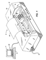
- FIG. 1 illustrates a perspective view of a color thermal ink jet printing system 8 which incorporates region-dependent image processing of the present invention.
- An ink jet printer 9 is coupled to an personal computer 10, including a monitor 11 and a keyboard 12, which provides image information to the printer 9 for printing. While an ink jet printer 9 is illustrated, other liquid ink printers are also within the scope of the invention.
- Printer 9 includes four ink jet printhead cartridges 14, 15, 16, and 18 detachably mounted in a housing 20 attached to a carriage 22 supported by carriage rails 24. The carriage rails 24 are supported by a frame 26 of the ink jet printer 9.
- Each printhead cartridge includes an ink container holding ink, including cyan, magenta, yellow and/or black for supply to a thermal ink jet printhead which selectively expels droplets of ink under control of electrical signals received from a controller (not shown) of the printer 9 through an electrical cable (not shown).
- Each of the printhead cartridges 14, 15, 16, and 18, can be coupled to the printhead 34 such that a portion or segment of the linear array of nozzles is associated with each of the color cartridges. It is also, however, possible that each of the printhead cartridges 14, 15, 16, and 18 can be individually coupled to a single printhead such that each printhead deposits ink on the recording medium 30 of a single color such as cyan, magenta, yellow or black under control of the controller.
- the color printing system 8 of FIG. 1 can be used to print detailed and information intensive color images. Such color images and the printing thereof often involves sophisticated and complex image processing.
- complex image processing is illustrated in FIG. 2 and FIG. 3.
- color image processing is often necessary along an intercolor boundary 40 which is located between a first color 42 and a second color 44 which can include black.
- intercolor bleed often occurs especially in liquid ink printers where different colored inks or different types of inks, such as fast drying and slow drying, come in contact with each other and bleed together. Such intercolor bleeding is unacceptable.
- FIG. 3 One approach to reducing intercolor bleed is illustrated in FIG. 3 and is known as pixel etching.
- Pixel etching introduces a region 46 where no ink is deposited between the inks. Such a no ink region effectively reduces intercolor bleed as is well known.
- boundaries are not only extremely difficult to detect but also difficult to etch.
- color printers are often sold to different markets or market segments where oftentimes the majority of jobs printed by such color printers have relatively small areas of color, such as in a business setting.
- Such business documents can be comprised of text with only a small amount of color included in, for instance, a small color logo or a graphic.
- the present invention therefore, provides a way to limit the complex color image processing to only those portions of the image which actually require processing, that is, those that contain color. Consequently, even though the present invention includes additional processing steps which do take some amount of time, it is usually insignificant relative to the image processing routines which it replaces.
- the printing system 8 of the present invention includes a host processor 50 located in the personal computer 10 as is known by those skilled in the art.
- the host processor 50 can include one of many known microprocessors which is programmable through software instructions and is typically connected to a bus 52. Coupled to the bus 52 are other elements of an information processing system including a read only memory (ROM) 54, a Random Access Memory (RAM) 56, the monitor 11, the keyboard 12, also known as a user interface including a mouse and other known interfaces such as touch screen panels, the printer 9, and a print driver 58.
- ROM read only memory
- RAM Random Access Memory
- a user viewing the monitor 11 creates a document thereon through the user interface 12.
- a page descriptive language file (PDL file) 60 is created by the host processor and stored in the Random Access Memory 56.
- This PDL file typically includes image information including images which have been defined in colorimetric terms R, G, and B typically digital in nature.
- the printer 9 generates an output image which is defined as existing in a color space known as C, M, Y, and K. Consequently, to print an image existing as a PDL file 60, not only must a transformation from the color space of RGB to the color space of CMY and K be made, but other imaging processing functions such as the previously described pixel etching must be performed.
- the print driver 58 consequently decomposes or renders the PDL file 60 to create a plurality of bitmaps including a cyan bitmap 62, a magenta bitmap 64, a yellow bitmap 66 and a K or black bitmap 68 which once generated can either be stored in the RAM 56 or transferred to the printer 9 if no additional image processing functions are to be performed by the print driver 58.
- the present invention includes an image segmentation or tag block processor 70, as illustrated in FIG. 4, which in a practical implementation may be included in the print driver 58 but which has been shown separately therefrom for purposes of illustration.
- the image segmentation processor 70 operates on the C, Y, M and K bitmaps 62, 64, 66, and 68 to determine if any of the information thereon includes color information.
- the areas of color information are then tagged, such that only those tagged areas are color processed and the remaining areas are not. If a page of information contains no areas which require processing, the tag block processor is not invoked. It is also possible to detect purely black and white pages, of course, even earlier in the image path and any color processing processing is bypassed altogether.
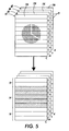
- FIG. 5 illustrates a schematic depiction of the operation of the image segmentation processor 70.
- the combination of the cyan, magenta, yellow and black bitmaps would provide the color image of FIG. 2.
- the tag block processor 70 would delineate, or segment, each of the bitmaps into portions each of which corresponds to another similarly sized area from another bitmap. For instance, as illustrated in FIG. 5, the tag block processor 70 divides the bitmaps into a plurality of portions 72 each of which is equivalent to a swath of the printhead printing the entire width of the page.
- the tag block processor then analyzes each of the portions 72 from a corresponding portion of each of the bitmaps 62, 64, 66 and 68, to determine if there is any color information contained in any of the four corresponding tag blocks such as 72A, 72B, 72C and 72D. If color information is contained therein, the portions containing the color information here illustrated as a block 74 of five swaths is marked or tagged. It is this block 74 which is then color processed according to the desired color processing and the remaining portions of the image including portions 72 and 76 are not color processed.
- FIG. 6 illustrates a different segmenting scheme of the present invention which includes not only segmenting the pixel bitmaps into a plurality of scan lines but also subdividing each of the scan lines into a plurality of smaller portions which is here illustrated as being a one quarter portion 80 of the portion 72.
- Corresponding portions of each bitmap are 80A, 80B, 80C and 80D.
- the plurality of these portions 80 are also marked or tagged when color information is present which is illustrated as an area 82.
- the remaining areas illustrated as including white space contain no color information and are not color processed. It is possible to select the size of the areas which are to be analyzed for color information therein depending on the type of anticipated use of the printer.
- the optimum configuration and size of the tag blocks is a function of the hardware and software architecture and the anticipated market's document demographics. It should be established through experimentation and analysis during the design of the product and coded as a software variable for potential future upgrade as market conditions change.
- the tag block processor 70 can include either a hardware implementation or a software implementation according to well known practices. If the tag block processor 70 includes programming operations, it is known and commonplace to program such control functions and any logic with software instructions for conventional or general purpose microprocessors as are included in the printing system 8 of the present invention. This is taught by many various prior patents and commercial products. Such programming or software may, of course, vary depending on the particular functions, software type, and microprocessor or other computer or other system utilized but will be available to or readily programmable without undue experimentation from, functional descriptions such as those provided herein, or prior knowledge of functions which are conventional together with general knowledge in the software and computer arts. This can include object oriented software development operation environments such as C++. Alternatively, the disclosed system or method may be implemented partially or fully in hardware using standard logic circuits or a single chip using VLSI designs.
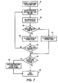
- FIG. 7 illustrates a flow chart for the operations performed by the tag block processor 70, either implemented in software or as hardware.
- the cyan, magenta, yellow and black bitmaps are generated for each image plane from the PDL file 60 as illustrated at step 92.
- bitmaps for each image plane have been generated and the tag block size has been determined, a first tag block from each of the image planes is selected such that each of the selected tag blocks corresponds to a certain portion of the printed image.
- These portions can be stored in related buffers as illustrated in FIG. 4 where a cyan buffer 94, a yellow buffer 96, a magenta buffer 98, and a black buffer 100 receive corresponding portions of each of the image planes.
- the size of these buffers can be equivalent to the size of the tag blocks or can be of other sizes depending on the implementation.
- a logical exclusive OR operation is applied to corresponding bytes of the selected tag blocks as illustrated at step 102 and as embodied by the exclusive OR operator 104 of FIG. 4.
- thirty-two bit segments of the tag blocks might be logically exclusively ORed together to determine whether or not any of the portions contain color information since thirty-two bit words in known personal computers are common. It is also possible, however, to exclusive OR a single bit from each of the tag blocks until it is determined that color is included within a tag block. Once color is found in one or more bitmaps, the next tag block can be examined.
- step 106 it is determined whether or not any resulting bits from the logical operation are equivalent to a 1. If, for instance, 32 bit words are exclusively ORed together by operator 104 then the resulting 32 bits from the logical operation of exclusively ORing all four planes together would result in a single 32 bit word. In this case, all 32 bits could be ORed together at OR gate 108 to determine if color has been found thereby providing an output of a 1 if so determined.
- a lookup table is established by either the host processor 50 under control of the print driver 58 or the tag block processor 70 to store indicating bits to indicate which of the tag block portions contain color information. Consequently, once any resulting bits are determined to be equal to 1 at step 106, a corresponding lookup table location is set to 1 at step 110. If, however, none of the resulting bits are equal to 1 at step 106, then the corresponding lookup table location is set to 0 at step 112 and as embodied in the lookup table 114 of FIG. 4.
- step 116 if it is determined that all of the tag blocks have not been selected, then a new tag block is selected at step 93 and the previously described operations are repeated for the newly selected tag block. If, however, all of the tag blocks have been selected and thus analyzed, the lookup table locations in the lookup table 114 are checked at step 118 to determine if any lookup table locations indicate that the previously analyzed tag blocks include color information. If, yes, then at step 120 color processing is applied to only the tagged portions of the image. Once the color processing has been completed, then the document is printed at step 122. Of course, if none of the lookup table locations 118 were tagged or set to a one at step 118, then the document is printed at step 122 without the application of any additional color processing.
- the region-dependent image processing of the present invention significantly reduces the amount of time required for image processing by pre-analyzing the entire page and identifying only the regions which need to be processed. In one example, it has been found that the present invention reduced the image processing time from approximately 40 seconds to less than one second. While it is possible that processing a color image covering a complete page might increase the processing time for that page using the present invention, overall processing time for color processing many documents decreases using the present invention. It is, therefore, apparent that there has been provided in accordance with the present invention a printing system having region dependent image processing that fully satisfies the aims and advantages hereinbefore set forth.
- the tag block processing or segmentation can be done by collecting and merging bounding box information in the PDL interpreter or the PDL interpreter could be modified to generate the bounding box information as it is decomposing the image. Or in the alternative, the output of the interpreter can be scanned to generate the same bounding box information.
- the present invention is not limited to liquid ink printers but is equally applicable to other printing systems such as four color offset and xerographic printing systems. For instance, such systems use trapping algorithms for which the present invention could be advantageously applied. Accordingly, it is intended to embrace all such alternatives, modifications and variations that fall within the scope of the appended claims.
Abstract
A liquid ink printing method having region dependent image processing for printing a color
image from image information generated by an image source. The method includes generating a
plurality of bitmaps (62, 64, 66, 68) from the image information, examining a corresponding portion
(72A, 72B, 72C, 72D) of each bitmap (62, 64, 66, 68) for color information, and applying color image
processing to only the examined corresponding portion (74) having color information. The method
of printing, including region dependent image processing, improves performance of complex image
processing operations by detecting and tagging portions of an image which require the complex
image processing operations. Only those regions that require complex image processing
operations are processed according to those processes and other information, such as text, are not
processed.
Description
This invention relates generally to printing systems and more particularly, although not
exclusively, concerned with printing systems having region-dependent image processing.
Liquid ink printers of the type frequently referred to as continuous stream or as drop-on-demand,
such as piezoelectric, acoustic, phase change wax-based, or thermal, have at least one
printhead from which droplets of ink are directed towards a recording medium. Within the printhead,
the ink is contained in a plurality of ink carrying conduits or channels. Power pulses cause the
droplets of ink to be expelled as required from orifices or nozzles at the ends of the channels.
In a thermal ink-jet printer, the power pulse is usually produced by a heater transducer or a
resistor, typically associated with one of the channels. Each resistor is individually addressable to
heat and vaporize ink in the channels. As voltage is applied across a selected resistor, a vapor
bubble grows in the associated channel and initially bulges toward the channel orifice followed by
collapse of the bubble. The ink within the channel then retracts and separates from the bulging ink
thereby forming a droplet moving in a direction away from the channel orifice and towards the
recording medium whereupon hitting the recording medium a dot or spot of ink is deposited. The
channel is then refilled by capillary action, which, in turn, draws ink from a supply container of liquid
ink.
The ink jet printhead may be incorporated into either a carriage type printer, a partial width
array type printer, or a page-width type printer. The carriage type printer typically has a relatively
small printhead containing the ink channels and nozzles. The printhead can be sealingly attached
to a disposable ink supply cartridge and the combined printhead and cartridge assembly is attached
to a carriage which is reciprocated to print one swath of information (equal to the length of a column
of nozzles), at a time, on a stationary recording medium, such as paper or a transparency. After the
swath is printed, the paper is stepped a distance equal to the height of the printed swath or a portion
thereof, so that the next printed swath is contiguous or overlapping therewith. This procedure is
repeated until the entire page is printed. In contrast, the page width printer includes a stationary
printhead having a length sufficient to print across the width or length of a sheet of recording
medium at a time. The recording medium is continually moved past the page width printhead in a
direction substantially normal to the printhead length and at a constant or varying speed during the
printing process. A page width ink-jet printer is described, for instance, in US-A-5 192 959.
Printers typically print color and/or monochrome images received from an image output
device or document creator such as a personal computer, a scanner, or a workstation. The color
images printed are produced by printing with several colored inks or colorants of different colors at a
time. The color of the ink and amount of ink deposited by the printer is determined according to
image information received from the document creator. The document creator provides an input
digital gray-scale image, which is either defined in monochromatic terms, colorimetric terms, or both.
The amount of gray level is typically defined by an input pixel value ranging from 0 to 255, where 0
is equal to white, 255 is equal to black, and value therebetween are shades of gray. Commonly this
description may be part of a Page Description Language (PDL) file describing the document. In the
case of computer generated images, colors defined by the user at the user interface of a workstation
can be defined initially in color space of tristimulus values. These colors are defined independently
of any particular device, and accordingly reference is made to the information as being "device
independent".
The printer, on the other hand, has an output which is dependent on the device or "device
dependent". This dependency is due, in part, to the fact that while the input digital gray scale image
includes pixels having a wide range of gray scale values, the output image generated by the printer
is a binary image formed from a plurality of ink drops or spots wherein the absence of a spot defines
the level of white and the presence of a spot defines black. Consequently, a transformation must be
made from the input digital gray scale image to the printed binary image since the binary image
includes binary information which either has a gray level value of zero (white) or one (black), but not
levels of gray therebetween. These transformations, from an input image to an output image, are
made with a number of known algorithms, including an algorithm known as the error diffusion
algorithm which converts the input gray scale image into high frequency binary texture patterns that
contain the same average gray scale information as the input image.
Color printers also include an output which can be defined as existing in a color space
called CMYK (cyan-magenta-yellow-key or black) which is uniquely defined for the printer by its
capabilities and colorants. Such printers operate by the addition of overlapping multiple layers of ink
or colorant in layers to form a page. These multiple layers are derived from the PDL description of a
page which is decomposed into multiple color planes or bitmaps, each plane or bitmap
corresponding to C, M, Y, and K.
Because liquid inks are used, certain ink related problems arise, including intercolor bleed
where inks of different colors come in contact with one another and bleed together. Likewise, some
inks do not always provide for optimum color rendition of a desired image. Consequently, to
achieve a desired color response the image must be supplemented with additional inks, for
instance, to increase the optical density. In certain other instances, it is desirable to reduce the
amount of ink when the amount of ink is too great resulting in drying problems. In these and other
known instances, the C, M, Y, and K image bitmaps are altered or modified to achieve the desired
output. Such modifications, however, can be time consuming resulting in reduced throughput of the
printing system.
US-A-5 029 224 describes a marked region recognition apparatus which recognizes an
arbitrary marked region of a document image from a marked signal which indicates whether or not
there exists a mark which indicates the marked region. The marked region recognition apparatus
uses an output image data of an image reader which makes a scan at a predetermined direction to
read an arbitrary region of a document image which is indicated by a mark.
US-A-5 247 583 describes an image segmentation method and apparatus. An image
processing area is divided into a plurality of small areas which are allowed to overlap one another.
One or a plurality of pixels in a region to be segmented and in a region not to be segmented are
specified. By processing, a particular region can be segmented out of the region.
US-A-5 513 282 describes a method and apparatus for controlling the execution of image
processing operations carried out on an array of image signals, the specific operations having been
identified by a plurality of predefined windows. The windows are divided into a plurality of regions,
the boundaries of which correspond to transitions from one region to another.
In accordance with one aspect of the present invention, there is provided a method of
printing a color image with a printer from image information generated by an image source, the
method comprising the steps of: a) generating a plurality of bitmaps from the image information; b)
processing the bitmaps in accordance with color information; and c) printing the color image;
characterized in that the method further comprises d) examining at least one corresponding portion
of each bitmap for color information; and e) applying color image processing to only the examined
corresponding portion having color information.
For a better understanding of the present invention, reference will now be made, by way of
example only, to the accompanying drawings in which:-
While the present invention will be described in connection with a preferred embodiment
thereof, it will be understood that it is not intended to limit the invention to that embodiment.
FIG. 1 illustrates a perspective view of a color thermal ink jet printing system 8 which
incorporates region-dependent image processing of the present invention. An ink jet printer 9 is
coupled to an personal computer 10, including a monitor 11 and a keyboard 12, which provides
image information to the printer 9 for printing. While an ink jet printer 9 is illustrated, other liquid ink
printers are also within the scope of the invention. Printer 9 includes four ink jet printhead cartridges
14, 15, 16, and 18 detachably mounted in a housing 20 attached to a carriage 22 supported by
carriage rails 24. The carriage rails 24 are supported by a frame 26 of the ink jet printer 9. The
carriage 20 moves in a scanning direction 28 reciprocating across a recording medium 30, such as
a sheet of paper or a transparency, which is advanced in a direction indicated by arrow 32 for
printing. Each printhead cartridge includes an ink container holding ink, including cyan, magenta,
yellow and/or black for supply to a thermal ink jet printhead which selectively expels droplets of ink
under control of electrical signals received from a controller (not shown) of the printer 9 through an
electrical cable (not shown).
As the carriage 22 reciprocates back and forth across the recording medium 30, droplets
of ink are expelled from selected ones of a plurality of printhead nozzles of a printhead 34 in a
swath. The nozzles, also known as ink ejecting orifices, are typically arranged in a linear array
substantially perpendicular to the scanning direction 28. During each pass of the carriage 22, the
recording medium 30 is held in a stationary position. At the end of each pass, however, the
recording medium is stepped by a stepping mechanism under control of the printer controller in the
direction of the arrow 32. For a more detailed explanation of the printhead and printing thereby
reference is made to US-AS 571 599 and US Reissue No. 32,572.
Each of the printhead cartridges 14, 15, 16, and 18, can be coupled to the printhead 34
such that a portion or segment of the linear array of nozzles is associated with each of the color
cartridges. It is also, however, possible that each of the printhead cartridges 14, 15, 16, and 18 can
be individually coupled to a single printhead such that each printhead deposits ink on the recording
medium 30 of a single color such as cyan, magenta, yellow or black under control of the controller.
The color printing system 8 of FIG. 1 can be used to print detailed and information
intensive color images. Such color images and the printing thereof often involves sophisticated and
complex image processing. One example of complex image processing is illustrated in FIG. 2 and
FIG. 3. As illustrated in FIG. 2, color image processing is often necessary along an intercolor
boundary 40 which is located between a first color 42 and a second color 44 which can include
black. Along the intercolor boundary, intercolor bleed often occurs especially in liquid ink printers
where different colored inks or different types of inks, such as fast drying and slow drying, come in
contact with each other and bleed together. Such intercolor bleeding is unacceptable.
One approach to reducing intercolor bleed is illustrated in FIG. 3 and is known as pixel
etching. Pixel etching introduces a region 46 where no ink is deposited between the inks. Such a
no ink region effectively reduces intercolor bleed as is well known. Unfortunately, however, such
boundaries are not only extremely difficult to detect but also difficult to etch. Software exists which
detects color boundaries and subsequently processes the necessary pixel etching. This procedure,
however, for instance, when performed for an entire page having a resolution of 600 by 600 by 1
byte per pixel can take approximately 20 minutes. For this reason, such implementations are often
abandoned or dramatically reduced in complexity thereby creating additional problems where
implemented such as in an expensive ASIC with a significant amount of supporting memory.
It has been found, however, that color printers are often sold to different markets or market
segments where oftentimes the majority of jobs printed by such color printers have relatively small
areas of color, such as in a business setting. Such business documents can be comprised of text
with only a small amount of color included in, for instance, a small color logo or a graphic. The
present invention, therefore, provides a way to limit the complex color image processing to only
those portions of the image which actually require processing, that is, those that contain color.
Consequently, even though the present invention includes additional processing steps which do
take some amount of time, it is usually insignificant relative to the image processing routines which it
replaces.
As illustrated in FIG. 4, the printing system 8 of the present invention includes a host
processor 50 located in the personal computer 10 as is known by those skilled in the art. The host
processor 50 can include one of many known microprocessors which is programmable through
software instructions and is typically connected to a bus 52. Coupled to the bus 52 are other
elements of an information processing system including a read only memory (ROM) 54, a Random
Access Memory (RAM) 56, the monitor 11, the keyboard 12, also known as a user interface
including a mouse and other known interfaces such as touch screen panels, the printer 9, and a
print driver 58.
In a typical operation of the printing system 8, a user viewing the monitor 11 creates a
document thereon through the user interface 12. Once the document is created through
cooperation with the host processor 50, a page descriptive language file (PDL file) 60 is created by
the host processor and stored in the Random Access Memory 56.
This PDL file typically includes image information including images which have been
defined in colorimetric terms R, G, and B typically digital in nature. The printer 9, however,
generates an output image which is defined as existing in a color space known as C, M, Y, and K.
Consequently, to print an image existing as a PDL file 60, not only must a transformation from the
color space of RGB to the color space of CMY and K be made, but other imaging processing
functions such as the previously described pixel etching must be performed. The print driver 58, as
is known by those skilled in the art, consequently decomposes or renders the PDL file 60 to create a
plurality of bitmaps including a cyan bitmap 62, a magenta bitmap 64, a yellow bitmap 66 and a K or
black bitmap 68 which once generated can either be stored in the RAM 56 or transferred to the
printer 9 if no additional image processing functions are to be performed by the print driver 58.
Since it has been determined that many color processing operations take a significant
amount of time if applied to an entire page of information as described by the PDL file 60, the
present invention includes an image segmentation or tag block processor 70, as illustrated in FIG. 4,
which in a practical implementation may be included in the print driver 58 but which has been shown
separately therefrom for purposes of illustration. The image segmentation processor 70 operates on
the C, Y, M and K bitmaps 62, 64, 66, and 68 to determine if any of the information thereon includes
color information. The areas of color information are then tagged, such that only those tagged areas
are color processed and the remaining areas are not. If a page of information contains no areas
which require processing, the tag block processor is not invoked. It is also possible to detect purely
black and white pages, of course, even earlier in the image path and any color processing
processing is bypassed altogether.
FIG. 5 illustrates a schematic depiction of the operation of the image segmentation
processor 70. As illustrated, the combination of the cyan, magenta, yellow and black bitmaps would
provide the color image of FIG. 2. Initially, the tag block processor 70 would delineate, or segment,
each of the bitmaps into portions each of which corresponds to another similarly sized area from
another bitmap. For instance, as illustrated in FIG. 5, the tag block processor 70 divides the
bitmaps into a plurality of portions 72 each of which is equivalent to a swath of the printhead printing
the entire width of the page. The tag block processor then analyzes each of the portions 72 from a
corresponding portion of each of the bitmaps 62, 64, 66 and 68, to determine if there is any color
information contained in any of the four corresponding tag blocks such as 72A, 72B, 72C and 72D.
If color information is contained therein, the portions containing the color information here illustrated
as a block 74 of five swaths is marked or tagged. It is this block 74 which is then color processed
according to the desired color processing and the remaining portions of the image including portions
72 and 76 are not color processed.
FIG. 6 illustrates a different segmenting scheme of the present invention which includes
not only segmenting the pixel bitmaps into a plurality of scan lines but also subdividing each of the
scan lines into a plurality of smaller portions which is here illustrated as being a one quarter portion
80 of the portion 72. Corresponding portions of each bitmap are 80A, 80B, 80C and 80D. As
before, the plurality of these portions 80 are also marked or tagged when color information is
present which is illustrated as an area 82. The remaining areas illustrated as including white space
contain no color information and are not color processed. It is possible to select the size of the
areas which are to be analyzed for color information therein depending on the type of anticipated
use of the printer. The optimum configuration and size of the tag blocks is a function of the
hardware and software architecture and the anticipated market's document demographics. It should
be established through experimentation and analysis during the design of the product and coded as
a software variable for potential future upgrade as market conditions change.
The tag block processor 70 can include either a hardware implementation or a software
implementation according to well known practices. If the tag block processor 70 includes
programming operations, it is known and commonplace to program such control functions and any
logic with software instructions for conventional or general purpose microprocessors as are included
in the printing system 8 of the present invention. This is taught by many various prior patents and
commercial products. Such programming or software may, of course, vary depending on the
particular functions, software type, and microprocessor or other computer or other system utilized
but will be available to or readily programmable without undue experimentation from, functional
descriptions such as those provided herein, or prior knowledge of functions which are conventional
together with general knowledge in the software and computer arts. This can include object
oriented software development operation environments such as C++. Alternatively, the disclosed
system or method may be implemented partially or fully in hardware using standard logic circuits or
a single chip using VLSI designs.
FIG. 7 illustrates a flow chart for the operations performed by the tag block processor 70,
either implemented in software or as hardware. The cyan, magenta, yellow and black bitmaps are
generated for each image plane from the PDL file 60 as illustrated at step 92. After bitmaps for
each image plane have been generated and the tag block size has been determined, a first tag
block from each of the image planes is selected such that each of the selected tag blocks
corresponds to a certain portion of the printed image. These portions can be stored in related
buffers as illustrated in FIG. 4 where a cyan buffer 94, a yellow buffer 96, a magenta buffer 98, and
a black buffer 100 receive corresponding portions of each of the image planes. The size of these
buffers can be equivalent to the size of the tag blocks or can be of other sizes depending on the
implementation. Once a tag block has been selected for each image plane at step 93, a logical
exclusive OR operation is applied to corresponding bytes of the selected tag blocks as illustrated at
step 102 and as embodied by the exclusive OR operator 104 of FIG. 4. In an actual
implementation, thirty-two bit segments of the tag blocks might be logically exclusively ORed
together to determine whether or not any of the portions contain color information since thirty-two bit
words in known personal computers are common. It is also possible, however, to exclusive OR a
single bit from each of the tag blocks until it is determined that color is included within a tag block.
Once color is found in one or more bitmaps, the next tag block can be examined. It is not necessary
to exclusive OR every pixel of a tag block but only to exclusive OR pixels of a tag block until at least
one result indicates that color information is contained within a tag block. At step 106, it is
determined whether or not any resulting bits from the logical operation are equivalent to a 1. If, for
instance, 32 bit words are exclusively ORed together by operator 104 then the resulting 32 bits from
the logical operation of exclusively ORing all four planes together would result in a single 32 bit
word. In this case, all 32 bits could be ORed together at OR gate 108 to determine if color has been
found thereby providing an output of a 1 if so determined.
Since a plurality of corresponding tag block portions are analyzed to determine whether or
not color information is contained therein, a lookup table is established by either the host processor
50 under control of the print driver 58 or the tag block processor 70 to store indicating bits to
indicate which of the tag block portions contain color information. Consequently, once any resulting
bits are determined to be equal to 1 at step 106, a corresponding lookup table location is set to 1 at
step 110. If, however, none of the resulting bits are equal to 1 at step 106, then the corresponding
lookup table location is set to 0 at step 112 and as embodied in the lookup table 114 of FIG. 4. At
step 116, if it is determined that all of the tag blocks have not been selected, then a new tag block is
selected at step 93 and the previously described operations are repeated for the newly selected tag
block. If, however, all of the tag blocks have been selected and thus analyzed, the lookup table
locations in the lookup table 114 are checked at step 118 to determine if any lookup table locations
indicate that the previously analyzed tag blocks include color information. If, yes, then at step 120
color processing is applied to only the tagged portions of the image. Once the color processing has
been completed, then the document is printed at step 122. Of course, if none of the lookup table
locations 118 were tagged or set to a one at step 118, then the document is printed at step 122
without the application of any additional color processing.
It has been found that the region-dependent image processing of the present invention
significantly reduces the amount of time required for image processing by pre-analyzing the entire
page and identifying only the regions which need to be processed. In one example, it has been
found that the present invention reduced the image processing time from approximately 40 seconds
to less than one second. While it is possible that processing a color image covering a complete
page might increase the processing time for that page using the present invention, overall
processing time for color processing many documents decreases using the present invention. It is,
therefore, apparent that there has been provided in accordance with the present invention a printing
system having region dependent image processing that fully satisfies the aims and advantages
hereinbefore set forth.
While this invention has been described in conjunction with a specific embodiment thereof,
it is evident that many alternatives, modifications, and variations will be apparent to those skilled in
the art. For instance, the tag block processing or segmentation can be done by collecting and
merging bounding box information in the PDL interpreter or the PDL interpreter could be modified to
generate the bounding box information as it is decomposing the image. Or in the alternative, the
output of the interpreter can be scanned to generate the same bounding box information. In
addition, the present invention is not limited to liquid ink printers but is equally applicable to other
printing systems such as four color offset and xerographic printing systems. For instance, such
systems use trapping algorithms for which the present invention could be advantageously applied.
Accordingly, it is intended to embrace all such alternatives, modifications and variations that fall
within the scope of the appended claims.
Claims (10)
- A method of printing a color image with a printer (9) from image information generated by an image source (10), the method comprising the steps of:characterized in that the method further comprisesa) generating a plurality of bitmaps (62, 64, 66, 68) from the image information;b) processing the bitmaps (62, 64, 66, 68) in accordance with color information; andc) printing the color image;d) examining at least one corresponding portion (72; 80) of each bitmap (62, 64, 66, 68) for color information; ande) applying color image processing to only the examined corresponding portion (72A, 72B, 72C, 72D; 80A, 80B, 80C, 80D) having color information.
- A method according to claim 1, further comprising the step off) generating a tag (74; 82) for the examined corresponding portion having color information.
- A method according to claim 2, wherein step f) comprises logically exclusively ORing the corresponding portion (72; 80) of each of the plurality of bitmaps (62, 64, 66, 68) to generate the the tag (74; 82).
- A method according to any one of claims 1 to 3, wherein the corresponding portion (70A, 70B, 70C, 70D) of each bitmap (62, 64, 66, 68) is equivalent to a single swath of a liquid ink printhead (34).
- A method according to any one of claims 1 to 3, wherein the corresponding portion (80A, 80B, 80C, 80D) of each bitmap (62, 64, 66, 68) is equivalent to a portion of a single swath of the printhead (34).
- A method according to any one of claims 1 to 5, wherein step d) comprises examining one of the plurality of corresponding portions (72; 80) until the presence of color information is determined.
- A method according to claim 6, comprising secondly examining a succeeding one of the plurality of corresponding portions (72; 80) after the presence of color information is determined in the examined one of the plurality of corresponding portions (72; 80).
- A method according to claim 7, wherein step d) comprises examining corresponding bits of the plurality of bitmaps (62, 64, 66, 68).
- A method according to claim 8, wherein step d) comprises applying a logical exclusive OR operation to the corresponding bits.
- A method according to claim 9, comprising generating a tag (74; 82) for the examined corresponding portion determined to include color information as a result of the logical exclusive OR operation.
Applications Claiming Priority (2)
| Application Number | Priority Date | Filing Date | Title |
|---|---|---|---|
| US08/719,238 US5778160A (en) | 1996-09-24 | 1996-09-24 | Liquid ink printing system having region-dependent image processing |
| US719238 | 1996-09-24 |
Publications (1)
| Publication Number | Publication Date |
|---|---|
| EP0836154A1 true EP0836154A1 (en) | 1998-04-15 |
Family
ID=24889311
Family Applications (1)
| Application Number | Title | Priority Date | Filing Date |
|---|---|---|---|
| EP97307143A Withdrawn EP0836154A1 (en) | 1996-09-24 | 1997-09-15 | Printing systems |
Country Status (3)
| Country | Link |
|---|---|
| US (1) | US5778160A (en) |
| EP (1) | EP0836154A1 (en) |
| JP (1) | JP4215842B2 (en) |
Families Citing this family (17)
| Publication number | Priority date | Publication date | Assignee | Title |
|---|---|---|---|---|
| US6238044B1 (en) * | 2000-06-30 | 2001-05-29 | Silverbrook Research Pty Ltd | Print cartridge |
| US6020979A (en) * | 1998-03-23 | 2000-02-01 | Xerox Corporation | Method of encoding high resolution edge position information in continuous tone image information |
| US6429950B1 (en) * | 1998-12-31 | 2002-08-06 | Xerox Corporation | Method and apparatus for applying object characterization pixel tags to image data in a digital imaging device |
| US6690485B1 (en) * | 1999-02-18 | 2004-02-10 | Hewlett-Packard Development Company, L.P. | Pixel-density augmentation and adjustment with minimum data, in an incremental printer |
| JP2001222395A (en) * | 2000-02-10 | 2001-08-17 | Canon Inc | Information processor, information processing method and storage medium in which printer driver program is stored |
| US6873434B1 (en) * | 2000-05-16 | 2005-03-29 | Canon Kabushiki Kaisha | Color management of black data |
| US6533393B1 (en) | 2000-07-31 | 2003-03-18 | Hewlett-Packard Company | Printer with multiple printmodes per swath |
| US6995863B1 (en) * | 2000-08-19 | 2006-02-07 | Hewlett-Packard Development Company, L.P. | Discretionary dotting for artifact control in incremental printing |
| US7145668B2 (en) * | 2000-12-22 | 2006-12-05 | Canon Kabushiki Kaisha | Print system, printing method, information processing apparatus, printing apparatus, printer driver, and memory medium |
| US7027185B2 (en) * | 2001-07-30 | 2006-04-11 | Hewlett-Packard Development Company, L.P. | Linearization of an incremental printer by measurements referred to a media-independent sensor calibration |
| US6527366B1 (en) | 2001-08-28 | 2003-03-04 | Xerox Corporation | Method and arrangement for color substitution in a multi-color printing device |
| US7088465B2 (en) * | 2002-08-22 | 2006-08-08 | International Business Machines Corporation | Printing more or less of a web page |
| CN100453317C (en) * | 2004-01-05 | 2009-01-21 | 明基电通股份有限公司 | Image treating method for improving sawtooth effect |
| JP2005252361A (en) | 2004-03-01 | 2005-09-15 | Riso Kagaku Corp | Image processing apparatus and program |
| US7995237B2 (en) * | 2005-01-18 | 2011-08-09 | Canon Kabushiki Kaisha | Color transformation with black preservation |
| US20080122878A1 (en) * | 2006-11-24 | 2008-05-29 | Keefe Gary W | Apparatus and method for publishing computer-readable media |
| JP2010115843A (en) * | 2008-11-12 | 2010-05-27 | Seiko Epson Corp | Printer and printing method |
Citations (4)
| Publication number | Priority date | Publication date | Assignee | Title |
|---|---|---|---|---|
| US5168552A (en) * | 1991-10-29 | 1992-12-01 | Hewlett-Packard Company | Color separation in ink jet color graphics printing |
| US5383037A (en) * | 1991-11-06 | 1995-01-17 | Fuji Xerox Co., Ltd. | Apparatus for image coding and decoding based on color components in an image signal |
| JPH0795416A (en) * | 1993-09-21 | 1995-04-07 | Fuji Xerox Co Ltd | Encoding device for picture signal |
| EP0707281A2 (en) * | 1994-10-14 | 1996-04-17 | Seiko Epson Corporation | Ink jet colour printing system and method |
Family Cites Families (7)
| Publication number | Priority date | Publication date | Assignee | Title |
|---|---|---|---|---|
| JP2828645B2 (en) * | 1989-01-27 | 1998-11-25 | 株式会社リコー | Mark area judgment device |
| JPH03218581A (en) * | 1989-11-01 | 1991-09-26 | Hitachi Ltd | Picture segmentation method |
| JP3003261B2 (en) * | 1991-05-14 | 2000-01-24 | 富士ゼロックス株式会社 | Color image recognition device |
| US5475800A (en) * | 1991-10-29 | 1995-12-12 | Hewlett-Packard Company | Color separation in color graphics printing with limited memory |
| US5565886A (en) * | 1993-11-01 | 1996-10-15 | Microsoft Corporation | Method and system for rapidly transmitting multicolor or gray scale display data having multiple bits per pixel to a display device |
| CA2134249C (en) * | 1993-12-09 | 1999-09-07 | Leon C. Williams | Method and apparatus for controlling the processing of digital image signals |
| US5625711A (en) * | 1994-08-31 | 1997-04-29 | Adobe Systems Incorporated | Method and apparatus for producing a hybrid data structure for displaying a raster image |
-
1996
- 1996-09-24 US US08/719,238 patent/US5778160A/en not_active Expired - Lifetime
-
1997
- 1997-09-15 EP EP97307143A patent/EP0836154A1/en not_active Withdrawn
- 1997-09-16 JP JP25015297A patent/JP4215842B2/en not_active Expired - Fee Related
Patent Citations (4)
| Publication number | Priority date | Publication date | Assignee | Title |
|---|---|---|---|---|
| US5168552A (en) * | 1991-10-29 | 1992-12-01 | Hewlett-Packard Company | Color separation in ink jet color graphics printing |
| US5383037A (en) * | 1991-11-06 | 1995-01-17 | Fuji Xerox Co., Ltd. | Apparatus for image coding and decoding based on color components in an image signal |
| JPH0795416A (en) * | 1993-09-21 | 1995-04-07 | Fuji Xerox Co Ltd | Encoding device for picture signal |
| EP0707281A2 (en) * | 1994-10-14 | 1996-04-17 | Seiko Epson Corporation | Ink jet colour printing system and method |
Non-Patent Citations (1)
| Title |
|---|
| PATENT ABSTRACTS OF JAPAN vol. 095, no. 007 31 August 1995 (1995-08-31) * |
Also Published As
| Publication number | Publication date |
|---|---|
| US5778160A (en) | 1998-07-07 |
| JP4215842B2 (en) | 2009-01-28 |
| JPH10100453A (en) | 1998-04-21 |
Similar Documents
| Publication | Publication Date | Title |
|---|---|---|
| US5778160A (en) | Liquid ink printing system having region-dependent image processing | |
| KR100432307B1 (en) | Display list architecture having two dimensional array of zones | |
| US5847724A (en) | Method for diffusing errors according to spot size in a printed liquid ink image | |
| US8274668B2 (en) | Image processing apparatus, copier, and image processing method and program | |
| US6339480B1 (en) | Print driver for a color printer | |
| US6166828A (en) | Clearing ink jet nozzles during printing | |
| JP3175498B2 (en) | Black area identification method for ink jet color printing | |
| US6467866B1 (en) | Print control method and apparatus, and printing apparatus using the same | |
| US6886912B2 (en) | Method and apparatus for processing images having color combinations | |
| US7589860B2 (en) | Method, apparatus and computer program product for processing image data stored on a memory for rendering an image on a device | |
| US6318830B1 (en) | Image printing method, and apparatus thereof | |
| JP4661043B2 (en) | Printing apparatus, printing control apparatus, printing method, and program | |
| JP7286713B2 (en) | Inkjet recording apparatus and inkjet recording method | |
| AU5156700A (en) | Black text printing from page description languages | |
| EP0889434B1 (en) | Printer system and method for sending data hints of upcoming data | |
| US6655782B2 (en) | Printer device and method | |
| JP7171345B2 (en) | Image processing device, recording system, recording device, recording image detection method, and program | |
| EP0917094B1 (en) | Printer and printing control method | |
| JP2005028574A (en) | Image processing device and image printing device | |
| US20030081975A1 (en) | Method and apparatus for printing using staggered pens | |
| US6328396B1 (en) | Combining multiple printmodes into a single carriage sweep | |
| JP2023176506A (en) | Recording device, control method of recording device, and program | |
| JP2002361988A (en) | Serial printer and its operating method for printing test pattern | |
| EP2107788A1 (en) | Method and apparatus for printing a digital image | |
| JP3165539B2 (en) | Color inkjet recording device |
Legal Events
| Date | Code | Title | Description |
|---|---|---|---|
| PUAI | Public reference made under article 153(3) epc to a published international application that has entered the european phase |
Free format text: ORIGINAL CODE: 0009012 |
|
| AK | Designated contracting states |
Kind code of ref document: A1 Designated state(s): DE FR GB |
|
| 17P | Request for examination filed |
Effective date: 19981015 |
|
| AKX | Designation fees paid |
Free format text: DE FR GB |
|
| RBV | Designated contracting states (corrected) |
Designated state(s): DE FR GB |
|
| 17Q | First examination report despatched |
Effective date: 20030804 |
|
| STAA | Information on the status of an ep patent application or granted ep patent |
Free format text: STATUS: THE APPLICATION IS DEEMED TO BE WITHDRAWN |
|
| 18D | Application deemed to be withdrawn |
Effective date: 20040216 |