EP0836049B1 - Pulverized coal injection nozzle - Google Patents
Pulverized coal injection nozzle Download PDFInfo
- Publication number
- EP0836049B1 EP0836049B1 EP97120563A EP97120563A EP0836049B1 EP 0836049 B1 EP0836049 B1 EP 0836049B1 EP 97120563 A EP97120563 A EP 97120563A EP 97120563 A EP97120563 A EP 97120563A EP 0836049 B1 EP0836049 B1 EP 0836049B1
- Authority
- EP
- European Patent Office
- Prior art keywords
- coal
- ducts
- outlet
- central duct
- air
- Prior art date
- Legal status (The legal status is an assumption and is not a legal conclusion. Google has not performed a legal analysis and makes no representation as to the accuracy of the status listed.)
- Expired - Lifetime
Links
Images
Classifications
-
- F—MECHANICAL ENGINEERING; LIGHTING; HEATING; WEAPONS; BLASTING
- F23—COMBUSTION APPARATUS; COMBUSTION PROCESSES
- F23D—BURNERS
- F23D17/00—Burners for combustion simultaneously or alternately of gaseous or liquid or pulverulent fuel
-
- F—MECHANICAL ENGINEERING; LIGHTING; HEATING; WEAPONS; BLASTING
- F23—COMBUSTION APPARATUS; COMBUSTION PROCESSES
- F23C—METHODS OR APPARATUS FOR COMBUSTION USING FLUID FUEL OR SOLID FUEL SUSPENDED IN A CARRIER GAS OR AIR
- F23C7/00—Combustion apparatus characterised by arrangements for air supply
- F23C7/002—Combustion apparatus characterised by arrangements for air supply the air being submitted to a rotary or spinning motion
- F23C7/004—Combustion apparatus characterised by arrangements for air supply the air being submitted to a rotary or spinning motion using vanes
- F23C7/006—Combustion apparatus characterised by arrangements for air supply the air being submitted to a rotary or spinning motion using vanes adjustable
-
- F—MECHANICAL ENGINEERING; LIGHTING; HEATING; WEAPONS; BLASTING
- F23—COMBUSTION APPARATUS; COMBUSTION PROCESSES
- F23D—BURNERS
- F23D1/00—Burners for combustion of pulverulent fuel
- F23D1/02—Vortex burners, e.g. for cyclone-type combustion apparatus
-
- F—MECHANICAL ENGINEERING; LIGHTING; HEATING; WEAPONS; BLASTING
- F23—COMBUSTION APPARATUS; COMBUSTION PROCESSES
- F23D—BURNERS
- F23D17/00—Burners for combustion simultaneously or alternately of gaseous or liquid or pulverulent fuel
- F23D17/007—Burners for combustion simultaneously or alternately of gaseous or liquid or pulverulent fuel liquid or pulverulent fuel
-
- F—MECHANICAL ENGINEERING; LIGHTING; HEATING; WEAPONS; BLASTING
- F23—COMBUSTION APPARATUS; COMBUSTION PROCESSES
- F23D—BURNERS
- F23D2201/00—Burners adapted for particulate solid or pulverulent fuels
- F23D2201/20—Fuel flow guiding devices
-
- Y—GENERAL TAGGING OF NEW TECHNOLOGICAL DEVELOPMENTS; GENERAL TAGGING OF CROSS-SECTIONAL TECHNOLOGIES SPANNING OVER SEVERAL SECTIONS OF THE IPC; TECHNICAL SUBJECTS COVERED BY FORMER USPC CROSS-REFERENCE ART COLLECTIONS [XRACs] AND DIGESTS
- Y02—TECHNOLOGIES OR APPLICATIONS FOR MITIGATION OR ADAPTATION AGAINST CLIMATE CHANGE
- Y02E—REDUCTION OF GREENHOUSE GAS [GHG] EMISSIONS, RELATED TO ENERGY GENERATION, TRANSMISSION OR DISTRIBUTION
- Y02E20/00—Combustion technologies with mitigation potential
- Y02E20/34—Indirect CO2mitigation, i.e. by acting on non CO2directly related matters of the process, e.g. pre-heating or heat recovery
Definitions
- the present invention relates to a nozzle for injecting a solid fuel, such as pulverized coal, into a combustion chamber particularly suitable for being mounted on a burner providing a three-phase combustion to limit the production of nitrogen oxides.
- a solid fuel such as pulverized coal
- the nozzle of the present invention is especially designed for burners operating with either liquid or solid fuels and with either gas or liquid or solid fuels.
- nitrogen oxides are one of the most important pollutants produced during combustion processes, and are found in exhaust fumes released into the environment by steam generators, thermoelectric power stations and other industrial installations in which fossil fuels are burned.
- the formation of nitrogen oxides is due in part to the presence of N-compounds in the fuel (chemical NOx) and in part to the atmospheric nitrogen in the combustion air (thermal NOx).
- the NOx formation during the combustion process is dependent on a number of parameters, among which the main ones are the flame temperature, the time the combustion gasses remain in the high - temperature zone and the excess air. More specifically, formation of nitrogen oxides increases as the flame temperature increases, and can be minimised by keeping the peak values under control.
- a similar effect is produced when the fuel remains in the high-temperature zone for a short time and by a reducing atmosphere or an excess of fuel in the ignition area.
- the geometry of the air-coal mixture injector nozzle is of primary importance for the control of combustion and therefore for the production of NOx.
- .it is necessary to create areas that are poor in oxygen and rich in coal in the ignition area, and furthermore the time that the fuel remains therein must be such as to minimise the production of NOx and unburned substances.
- the recirculation streams around the end of the nozzle must be controlled in order to avoid excessively high temperatures and local fusion phenomena, which would damage the nozzle irreversibly.
- a tangential inlet for the air-coal mixture is provided to convey said mixture towards four or more ducts, whose cross-sections converge towards the combustion chamber and which are arranged in correspondence with the outlet into said chamber along an annulus coaxial with the primary air duct.
- jets of air-coal mixture rich in coal dust are formed.
- a duct with a diverging crosssection through which air is injected into the ignition area, said air being taken up through slots formed on the external shell of the nozzle. Injection of the air through these ducts is necessary in order to prevent the temperature of the nozzle from reaching excessively high values, but it also increases the level of oxygen in the ignition area, with an adverse effect on the reduction of NOx and therefore on the performance of the nozzle.
- EP-A-0163423 discloses a nozzle formed by an outer tubular member and an inner tubular member defining an annular channel therebetween.
- a divider cone extends between inner and outer tubular members.
- a plurality of V-shaped splitters are circumferentially spaced between the outer tubular member and the divider cone at the outlet portion of the nozzle, defining conduits for coal dust-rich air stream.
- Pie-shaped openings are formed through the outer tubular member over the splitters to admit secondary air in the annular space between the divider cone and the outer tubular member.
- An axially movable tip is formed at the end of the inner tubular member to regulate the amount of air flowing through the opening defined between the tip and the cone.
- the coal dust-poor air stream which still contain coal, is fed to the combination chamber within the flame region, and a central flame is additionally generated, which increases not only the flame stability, but also the risk of burning the nozzle end.
- secondary air is sucked through pie-shaped openings to reduce the temperature, but this also increases the amount of available combustion air, resulting in a higher NOx production.
- Axially movable tip provides for a partitioning of the coal dust-rich and coal dust-poor air streams and a control of the amount of coal dust present in the coal dust-rich air stream, but anyway all these streams are admitted into the flame region.
- the object of the present invention is to provide a nozzle for injection of solid fuel-air mixtures, the solid fuel being coal dust or the like, capable of giving improved combustion conditions with respect to known devices of this kind.
- the nozzle according to the invention is designed to be installed at the outlet end of a burner in a coaxial relationship to the primary air duct in a conventional way.
- the nozzle according to the invention comprises a fixed part 1 which serves the purpose of concentrating the coal dust into physically separated streams, and a mobile member 2 which serves the purpose of registering the outflow of primary and combustion air according to the manner in which the desired combustion process is to be carried out.
- the fixed part 1 consists of a group of at least three ducts 3 with the shape of a truncated cone converging towards a combustion chamber, not shown, suitable to be arranged according to an annulus coaxial with the primary air duct of the burner and an oil lance within a central tube 4, so as to transform 100% of the annulus section at the inlet into 40 - 60% of the section at the outlet.
- a combustion chamber not shown
- FIG 1 an embodiment with four ducts 3 is shown. In this way the coal dust, which is already concentrated toward the wall of the primary air duct by a swirler not shown, installed in said duct upstream from the nozzle, is divided into various streams characterized by a low air/coal ratio.
- air ducts 5 are formed each having a section which increases towards the combustion chamber and communicating with an inner duct 6 delimited by ducts 3 therearound. Therefore, at the nozzle outlet the outlet ports of air duct 5 alternate with those of air ducts 3.
- the mobile member 2 coaxial with the oil lance, has a conical cup shape and can be displaced between two end positions and a plurality of intermediate positions, as it is slidingly mounted on central tube 4 and is moved by means of a rod, not shown, along inner duct 6.
- the primary air transporting the coal dust reaches the nozzle, as stated above, with a coal dust-rich stream at the periphery of the air duct and a coal dust-poor stream at the centre.
- the coal dust-rich stream enters coal ducts 3 of fixed part 1 of the nozzle, while the coal dust-poor stream, flowing through the central section of primary air duct of the burner, enter inner duct 6 and is divided in two sub-streams depending on the position of mobile part 2 of the nozzle.
- a first sub-stream flows through air duct 5 and the second one is directed toward the outlet of inner duct 6 and fed to the combustion chamber through the passage defined by the outlet end of inner duct 6 and mobile member 2 of the nozzle coaxial thereon.
- Inclined plates 7 are positioned at the nozzle outlet in correspondence with the outlets from the air ducts 5.
- Inclined plates 7 have the aim of deflecting radially away from the centre the coal dust-poor air stream of primary air, for mixing it with the secondary air, and have an inclination of between 0 and 45°, optionally adjustable in a known manner by means of a control rod, not shown.
- ducts 3 for the air-coal mixture are tubular sectors of an annulus with a cross section that decreases from the inlet to the outlet, which are welded at their inlet end to a support 8 made up of two concentric annular members connected by radial arms not shown, while at their outlet ends ducts 3 are connected by means of circumferential tie rods 9 which give adequate allowance for thermal dilatation.
- composition of the two-phase mixture at the burner outlet depends upon performance of the process of mixing the coal dust poor and the coal dust rich air streams, this composition being the basic parameter for control of emission of NOx, unburned fuel and flame stability.
- the nozzle according to the invention has been installed on a burner.
- the burner has been tested at full scale underlining the following performances:
Landscapes
- Engineering & Computer Science (AREA)
- Chemical & Material Sciences (AREA)
- Combustion & Propulsion (AREA)
- Mechanical Engineering (AREA)
- General Engineering & Computer Science (AREA)
Description
- The present invention relates to a nozzle for injecting a solid fuel, such as pulverized coal, into a combustion chamber particularly suitable for being mounted on a burner providing a three-phase combustion to limit the production of nitrogen oxides. The nozzle of the present invention is especially designed for burners operating with either liquid or solid fuels and with either gas or liquid or solid fuels.
- It is a known fact that nitrogen oxides are one of the most important pollutants produced during combustion processes, and are found in exhaust fumes released into the environment by steam generators, thermoelectric power stations and other industrial installations in which fossil fuels are burned. The formation of nitrogen oxides is due in part to the presence of N-compounds in the fuel (chemical NOx) and in part to the atmospheric nitrogen in the combustion air (thermal NOx). The NOx formation during the combustion process is dependent on a number of parameters, among which the main ones are the flame temperature, the time the combustion gasses remain in the high - temperature zone and the excess air. More specifically, formation of nitrogen oxides increases as the flame temperature increases, and can be minimised by keeping the peak values under control. A similar effect is produced when the fuel remains in the high-temperature zone for a short time and by a reducing atmosphere or an excess of fuel in the ignition area.
- From what has been stated above it is clear that a combined control of the above mentioned working parameters will allow the formation of nitrogen oxides during combustion to be limited.
- In burners in which it is possible to burn solid fuel in powder form, for example coal dust, the geometry of the air-coal mixture injector nozzle is of primary importance for the control of combustion and therefore for the production of NOx. In particular .it is necessary to create areas that are poor in oxygen and rich in coal in the ignition area, and furthermore the time that the fuel remains therein must be such as to minimise the production of NOx and unburned substances. Finally, the recirculation streams around the end of the nozzle must be controlled in order to avoid excessively high temperatures and local fusion phenomena, which would damage the nozzle irreversibly. In a nozzle for solid fuels of a known type manufactured by Foster Wheeler Energy Corporation, (see EP-A-0 554 014), a tangential inlet for the air-coal mixture is provided to convey said mixture towards four or more ducts, whose cross-sections converge towards the combustion chamber and which are arranged in correspondence with the outlet into said chamber along an annulus coaxial with the primary air duct. In this way jets of air-coal mixture rich in coal dust are formed. Between each mixture duct and the adjacent one there is a duct with a diverging crosssection, through which air is injected into the ignition area, said air being taken up through slots formed on the external shell of the nozzle. Injection of the air through these ducts is necessary in order to prevent the temperature of the nozzle from reaching excessively high values, but it also increases the level of oxygen in the ignition area, with an adverse effect on the reduction of NOx and therefore on the performance of the nozzle.
- EP-A-0163423 discloses a nozzle formed by an outer tubular member and an inner tubular member defining an annular channel therebetween. A divider cone extends between inner and outer tubular members. A plurality of V-shaped splitters are circumferentially spaced between the outer tubular member and the divider cone at the outlet portion of the nozzle, defining conduits for coal dust-rich air stream. Pie-shaped openings are formed through the outer tubular member over the splitters to admit secondary air in the annular space between the divider cone and the outer tubular member. An axially movable tip is formed at the end of the inner tubular member to regulate the amount of air flowing through the opening defined between the tip and the cone. As in EP-A-0554014, the coal dust-poor air stream, which still contain coal, is fed to the combination chamber within the flame region, and a central flame is additionally generated, which increases not only the flame stability, but also the risk of burning the nozzle end. To avoid this inconvenience secondary air is sucked through pie-shaped openings to reduce the temperature, but this also increases the amount of available combustion air, resulting in a higher NOx production. Axially movable tip provides for a partitioning of the coal dust-rich and coal dust-poor air streams and a control of the amount of coal dust present in the coal dust-rich air stream, but anyway all these streams are admitted into the flame region.
- The object of the present invention is to provide a nozzle for injection of solid fuel-air mixtures, the solid fuel being coal dust or the like, capable of giving improved combustion conditions with respect to known devices of this kind.
- The above object is achieved with the nozzle according to the present invention, the main features of which are defined in the characterising portion of
claim 1. - Further characteristics and advantages of the pulverized coal injection nozzle according to the present invention will become clear from the following description of a preferred embodiment thereof, given merely as an example and with reference to the enclosed drawings, in which:
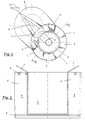
- Figure 1 is a perspective view of a nozzle for coal/air mixtures according to the present invention; and
- Figure 2 is a partial cross-sectional view of the nozzle of figure 1 taken along line II-II.
- The nozzle according to the invention is designed to be installed at the outlet end of a burner in a coaxial relationship to the primary air duct in a conventional way.
- With reference to the figures 1 and 2, the nozzle according to the invention comprises a
fixed part 1 which serves the purpose of concentrating the coal dust into physically separated streams, and amobile member 2 which serves the purpose of registering the outflow of primary and combustion air according to the manner in which the desired combustion process is to be carried out. - The
fixed part 1 consists of a group of at least threeducts 3 with the shape of a truncated cone converging towards a combustion chamber, not shown, suitable to be arranged according to an annulus coaxial with the primary air duct of the burner and an oil lance within a central tube 4, so as to transform 100% of the annulus section at the inlet into 40 - 60% of the section at the outlet. As an example, in figure 1 an embodiment with fourducts 3 is shown. In this way the coal dust, which is already concentrated toward the wall of the primary air duct by a swirler not shown, installed in said duct upstream from the nozzle, is divided into various streams characterized by a low air/coal ratio. Betweencoal ducts 3air ducts 5 are formed each having a section which increases towards the combustion chamber and communicating with aninner duct 6 delimited byducts 3 therearound. Therefore, at the nozzle outlet the outlet ports ofair duct 5 alternate with those ofair ducts 3. - The
mobile member 2, coaxial with the oil lance, has a conical cup shape and can be displaced between two end positions and a plurality of intermediate positions, as it is slidingly mounted on central tube 4 and is moved by means of a rod, not shown, alonginner duct 6. - The primary air transporting the coal dust reaches the nozzle, as stated above, with a coal dust-rich stream at the periphery of the air duct and a coal dust-poor stream at the centre. The coal dust-rich stream enters
coal ducts 3 of fixedpart 1 of the nozzle, while the coal dust-poor stream, flowing through the central section of primary air duct of the burner, enterinner duct 6 and is divided in two sub-streams depending on the position ofmobile part 2 of the nozzle. A first sub-stream flows throughair duct 5 and the second one is directed toward the outlet ofinner duct 6 and fed to the combustion chamber through the passage defined by the outlet end ofinner duct 6 andmobile member 2 of the nozzle coaxial thereon. Inclinedplates 7 are positioned at the nozzle outlet in correspondence with the outlets from theair ducts 5. - Inclined
plates 7 have the aim of deflecting radially away from the centre the coal dust-poor air stream of primary air, for mixing it with the secondary air, and have an inclination of between 0 and 45°, optionally adjustable in a known manner by means of a control rod, not shown. - In an embodiment shown in figure 2, given as an example,
ducts 3 for the air-coal mixture are tubular sectors of an annulus with a cross section that decreases from the inlet to the outlet, which are welded at their inlet end to asupport 8 made up of two concentric annular members connected by radial arms not shown, while at theiroutlet ends ducts 3 are connected by means of circumferential tie rods 9 which give adequate allowance for thermal dilatation. - The composition of the two-phase mixture at the burner outlet depends upon performance of the process of mixing the coal dust poor and the coal dust rich air streams, this composition being the basic parameter for control of emission of NOx, unburned fuel and flame stability.
- According to the present invention, by suitably combining the position of the
mobile member 2 with the effect of thestationary part 1 it is possible to define an optimum solution to respond to the various requirements of different installations. - With mobile member 2 a long way back, the flame is longer, the combustion process is slow, so that NOx is minimum, but CO and unburned fuel are maximum.
- With mobile member 2 a long way forward, combustion is intense and localised, due to the high level of coal dust/air mixing, NOx are maximum, CO and unburned products minimum.
- The nozzle according to the invention has been installed on a burner. The burner has been tested at full scale underlining the following performances:
- a NOx reduction in the order of 50%, when oil and coal are burnt, as compared with traditional "CIRCULAR" type burners;
- during coal fuelling a reduction in the level of unburned products in the order of 50%, as compared with first generation "Low NOx" burner.
- Variations and/or modifications can be brought to the pulverized coal injection nozzle fuels according to the present invention, without departing from the scope of the invention itself, as defined in the appended claims.
Claims (6)
- A nozzle for the injection of solid fuel in dust form into a combustion chamber, to be installed at the outlet of a burner coaxially to the longitudinal axis of the latter, comprising a fixed annular part (1) divided into coal ducts (3) of a circumferential width that decreases towards said outlet section to form coal dust-rich air streams, a central duct (6) for a coal dust-poor air stream delimited by said coal ducts and having an outlet end, a central member (2) that is axially mobile within said central duct (6), for varying the cross section of the central duct delimited by said fixed annular part at said outlet end of said central duct (6), characterized in that air ducts (5) for the coal dust-poor air stream are formed between two adjacent coal ducts (3) in said fixed annular part (1) communicating with said central duct (6) and having a circumferential width increasing toward said outlet end, deflector means (7) for said coal dust-poor air stream being provided at the outlet from said air ducts (5) to direct the stream from each air duct in a direction diverging radially from said central duct.
- The nozzle according to claim 1, in which the inclination of said deflector means (7) is adjustable within a range of between 45° and 90° with respect to a longitudinal axis of said central duct (6).
- The nozzle according to one of the previous claims, in which the overall cross section of said ducts (3) for the coal dust-rich air stream at the inlet thereof is substantially equivalent to 100% of the section at the inlet of said fixed annular part (1), whereas the overall cross section of said coal ducts (3) at the outlet of said fixed annular part (1) is equal to 40-60% of the outlet section thereof.
- The nozzle according to one of the previous claims, in which said coal ducts (3) are axially fixed at their inlet ends to a support (8) formed by two concentric ring elements (8a, 8b) connected to each other and radially spaced at a distance substantially equal to the radial width of said coal ducts, said coal ducts being connected to one another by means of circumferential tie rods (9) at their outlet ends.
- The nozzle according to one of the previous claims, in which said mobile member (2) is a cup-shaped cone with a hollow part facing towards the combustion chamber.
- The nozzle according to one of the previous claims, in which a tubular housing (4) is provided in the central duct (6) to house an oil lance.
Priority Applications (2)
| Application Number | Priority Date | Filing Date | Title |
|---|---|---|---|
| DE1996617954 DE69617954T2 (en) | 1996-10-08 | 1996-10-08 | Kohlenstaubeinspritzdüse |
| EP97120563A EP0836049B1 (en) | 1996-10-08 | 1996-10-08 | Pulverized coal injection nozzle |
Applications Claiming Priority (2)
| Application Number | Priority Date | Filing Date | Title |
|---|---|---|---|
| EP96116099A EP0836048B1 (en) | 1996-10-08 | 1996-10-08 | Burner |
| EP97120563A EP0836049B1 (en) | 1996-10-08 | 1996-10-08 | Pulverized coal injection nozzle |
Related Parent Applications (1)
| Application Number | Title | Priority Date | Filing Date |
|---|---|---|---|
| EP96116099A Division EP0836048B1 (en) | 1996-10-08 | 1996-10-08 | Burner |
Publications (3)
| Publication Number | Publication Date |
|---|---|
| EP0836049A2 EP0836049A2 (en) | 1998-04-15 |
| EP0836049A3 EP0836049A3 (en) | 1998-04-29 |
| EP0836049B1 true EP0836049B1 (en) | 2001-12-12 |
Family
ID=8223275
Family Applications (2)
| Application Number | Title | Priority Date | Filing Date |
|---|---|---|---|
| EP96116099A Expired - Lifetime EP0836048B1 (en) | 1996-10-08 | 1996-10-08 | Burner |
| EP97120563A Expired - Lifetime EP0836049B1 (en) | 1996-10-08 | 1996-10-08 | Pulverized coal injection nozzle |
Family Applications Before (1)
| Application Number | Title | Priority Date | Filing Date |
|---|---|---|---|
| EP96116099A Expired - Lifetime EP0836048B1 (en) | 1996-10-08 | 1996-10-08 | Burner |
Country Status (4)
| Country | Link |
|---|---|
| US (2) | US5823764A (en) |
| EP (2) | EP0836048B1 (en) |
| DE (1) | DE69614547T2 (en) |
| DK (2) | DK0836049T3 (en) |
Families Citing this family (41)
| Publication number | Priority date | Publication date | Assignee | Title |
|---|---|---|---|---|
| ITFI980069A1 (en) * | 1998-03-25 | 1999-09-25 | Enel Spa | INNOVATIVE BURNER FOR LIQUID AND GASEOUS FUELS WITH LOW PRODUCTION OF NITROGEN OXIDES |
| US6375691B1 (en) | 1998-04-30 | 2002-04-23 | Pirelli Ambiente S.P.A. | Fuel composition which combusts instantaneously, method and plant therefor |
| JP2000257811A (en) * | 1999-03-03 | 2000-09-22 | Hitachi Ltd | Pulverized coal combustion method, pulverized coal combustion apparatus, and pulverized coal combustion burner |
| IT1316825B1 (en) * | 2000-03-22 | 2003-05-12 | Italcementi Spa | DEVICE FOR THE INJECTION OF SOLID FUELS INTO DUST FORMED IN A CONCRETE OVEN |
| US6524098B1 (en) * | 2000-05-16 | 2003-02-25 | John Zink Company Llc | Burner assembly with swirler formed from concentric components |
| US6475267B2 (en) | 2000-12-13 | 2002-11-05 | Foster Wheeler Energy Corporation | System and method for removing gas from a stream of a mixture of gas and particulate solids |
| US6745708B2 (en) * | 2001-12-19 | 2004-06-08 | Conocophillips Company | Method and apparatus for improving the efficiency of a combustion device |
| CA2555481A1 (en) * | 2004-02-12 | 2005-08-25 | Alstom Technology Ltd | Premix burner arrangement for operating a combustion chamber and method for operating a combustion chamber |
| US8348180B2 (en) * | 2004-06-09 | 2013-01-08 | Delavan Inc | Conical swirler for fuel injectors and combustor domes and methods of manufacturing the same |
| WO2007002422A1 (en) * | 2005-06-23 | 2007-01-04 | Georgia Tech Research Corporation | Systems and methods for integrated plasma processing of waste |
| FR2887597B1 (en) * | 2005-06-27 | 2010-04-30 | Egci Pillard | ANNULAR CONDUIT AND BURNER COMPRISING SUCH A CONDUCT |
| CA2515923A1 (en) * | 2005-08-05 | 2007-02-05 | Mark A. Dupuis | Nozzle |
| EP1783426B1 (en) * | 2005-11-07 | 2014-05-14 | Riello S.p.A. | Combustion head for a gas burner |
| US8308477B2 (en) * | 2006-03-01 | 2012-11-13 | Honeywell International Inc. | Industrial burner |
| US8689707B2 (en) * | 2006-05-26 | 2014-04-08 | Fuel Tech, Inc. | Ultra low NOx burner replacement system |
| AU2006203560B2 (en) * | 2006-08-17 | 2011-12-01 | The Babcock & Wilcox Company | Burner with center air jet |
| US20080096146A1 (en) * | 2006-10-24 | 2008-04-24 | Xianming Jimmy Li | Low NOx staged fuel injection burner for creating plug flow |
| US20080280238A1 (en) * | 2007-05-07 | 2008-11-13 | Caterpillar Inc. | Low swirl injector and method for low-nox combustor |
| DE102007021926A1 (en) * | 2007-05-10 | 2008-11-20 | Siemens Ag | Oil / slurry burner with injection atomization |
| US8434700B2 (en) * | 2008-04-30 | 2013-05-07 | General Electric Company | Methods and systems for mixing reactor feed |
| JP5332389B2 (en) * | 2008-08-08 | 2013-11-06 | 株式会社Ihi | Burner |
| EP2216291A1 (en) * | 2009-01-26 | 2010-08-11 | Casale Chemicals S.A. | Process and burner for production of syngas from hydrocarbons |
| JP5369899B2 (en) | 2009-05-27 | 2013-12-18 | 株式会社Ihi | Burner |
| US20120129111A1 (en) * | 2010-05-21 | 2012-05-24 | Fives North America Combustion, Inc. | Premix for non-gaseous fuel delivery |
| KR101547083B1 (en) * | 2011-04-01 | 2015-08-24 | 미츠비시 히타치 파워 시스템즈 가부시키가이샤 | Combustion burner, solid-fuel-fired burner, solid-fuel-fired boiler, boiler, and method for operating boiler |
| CN102767824B (en) * | 2012-07-06 | 2015-08-05 | 南阳市沧田工程机械有限公司 | A kind of new and effective coal powder burner |
| CN104033895A (en) * | 2014-06-28 | 2014-09-10 | 广西聚为能源科技有限公司 | Oxygen-enriched pulverized coal combustor |
| US10281140B2 (en) | 2014-07-15 | 2019-05-07 | Chevron U.S.A. Inc. | Low NOx combustion method and apparatus |
| EP3062019B1 (en) * | 2015-02-27 | 2018-11-21 | Ansaldo Energia Switzerland AG | Method and device for flame stabilization in a burner system of a stationary combustion engine |
| FI125911B (en) * | 2015-04-14 | 2016-04-15 | Fortum Oyj | Gas burner with low nitrogen oxide emissions and fuel gas combustion process |
| JP6231047B2 (en) * | 2015-06-30 | 2017-11-15 | 三菱日立パワーシステムズ株式会社 | Solid fuel burner |
| WO2018021248A1 (en) * | 2016-07-26 | 2018-02-01 | Jfeスチール株式会社 | Auxiliary burner for electric furnace |
| RU170744U1 (en) * | 2016-08-09 | 2017-05-05 | акционерное общество "Бийский котельный завод" (АО "БиКЗ") | FUEL BURNER |
| CN106287667B (en) * | 2016-10-08 | 2018-10-30 | 西安交通大学 | A kind of high temperature gases recirculating preheating type low-NOx combustor equipped with SOFA |
| JP6502462B2 (en) * | 2017-11-08 | 2019-04-17 | ボルカノ株式会社 | Mixed combustion burner device and boiler |
| US10557630B1 (en) | 2019-01-15 | 2020-02-11 | Delavan Inc. | Stackable air swirlers |
| CN111795381B (en) * | 2020-07-23 | 2022-07-19 | 郑州轻工业大学 | A swirl blade adjustable swirler for pulverized coal burner |
| CN112460594B (en) * | 2020-12-10 | 2025-05-13 | 泰山燃控(泰安)有限公司 | Dual fuel burner and boiler with staged ignition, staged air distribution and flue gas recirculation |
| CN112413588A (en) * | 2020-12-11 | 2021-02-26 | 上海铂纳森环境科技有限公司 | Low-nitrogen combustion device and method with medium and low calorific value |
| CN115289473B (en) * | 2022-08-12 | 2025-05-30 | 北京天地融创科技股份有限公司 | Gas-powder dual fuel burner |
| TWI863728B (en) * | 2023-11-30 | 2024-11-21 | 財團法人金屬工業研究發展中心 | Nozzle of low carbon emission burner |
Family Cites Families (15)
| Publication number | Priority date | Publication date | Assignee | Title |
|---|---|---|---|---|
| GB1410923A (en) * | 1971-12-15 | 1975-10-22 | Hotwork Ltd | Fluid fuel burners |
| US3904349A (en) | 1974-05-22 | 1975-09-09 | Babcock & Wilcox Co | Fuel burner |
| US4348170A (en) * | 1980-06-04 | 1982-09-07 | Foster Wheeler Energy Corporation | Dual register, split stream burner assembly with divider cone |
| DE3125901A1 (en) * | 1981-07-01 | 1983-01-20 | Deutsche Babcock Ag, 4200 Oberhausen | BURNER FOR BURNING DUST-MADE FUELS |
| US4479442A (en) * | 1981-12-23 | 1984-10-30 | Riley Stoker Corporation | Venturi burner nozzle for pulverized coal |
| AU577366B2 (en) * | 1984-04-27 | 1988-09-22 | Foster Wheeler Energy Corporation | Controlled flow, split stream burner assembly with sorbent injection |
| JP2526236B2 (en) | 1987-02-27 | 1996-08-21 | バブコツク日立株式会社 | Ultra low NOx combustion device |
| JP2776572B2 (en) * | 1989-07-17 | 1998-07-16 | バブコツク日立株式会社 | Pulverized coal burner |
| IT1238713B (en) * | 1990-04-20 | 1993-09-01 | Ente Naz Energia Elettrica | PERFECTED BURNER FOR OIL AND COMBUSTIBLE GASES WITH LOW NITROGEN OXIDE PRODUCTION. |
| CA2086399C (en) * | 1992-01-27 | 2004-03-30 | Joel Vatsky | Split stream burner assembly |
| US5388536A (en) * | 1992-03-25 | 1995-02-14 | Chung; Landy | Low NOx burner |
| US5240409A (en) * | 1992-04-10 | 1993-08-31 | Institute Of Gas Technology | Premixed fuel/air burners |
| DE4217879A1 (en) * | 1992-05-29 | 1993-12-02 | Babcock Energie Umwelt | Burner for dusty fuel |
| DE4325643A1 (en) * | 1993-07-30 | 1995-02-02 | Lentjes Kraftwerkstechnik | Burners for burning dusty fuel |
| US5697306A (en) * | 1997-01-28 | 1997-12-16 | The Babcock & Wilcox Company | Low NOx short flame burner with control of primary air/fuel ratio for NOx reduction |
-
1996
- 1996-10-08 DK DK97120563T patent/DK0836049T3/en active
- 1996-10-08 DE DE69614547T patent/DE69614547T2/en not_active Expired - Lifetime
- 1996-10-08 EP EP96116099A patent/EP0836048B1/en not_active Expired - Lifetime
- 1996-10-08 DK DK96116099T patent/DK0836048T3/en active
- 1996-10-08 EP EP97120563A patent/EP0836049B1/en not_active Expired - Lifetime
-
1997
- 1997-07-15 US US08/891,800 patent/US5823764A/en not_active Expired - Lifetime
- 1997-07-15 US US08/896,274 patent/US5964166A/en not_active Expired - Lifetime
Also Published As
| Publication number | Publication date |
|---|---|
| US5964166A (en) | 1999-10-12 |
| DE69614547T2 (en) | 2002-04-04 |
| EP0836049A2 (en) | 1998-04-15 |
| US5823764A (en) | 1998-10-20 |
| DK0836049T3 (en) | 2002-04-08 |
| EP0836048A1 (en) | 1998-04-15 |
| DE69614547D1 (en) | 2001-09-20 |
| EP0836048B1 (en) | 2001-08-16 |
| EP0836049A3 (en) | 1998-04-29 |
| DK0836048T3 (en) | 2001-12-17 |
Similar Documents
| Publication | Publication Date | Title |
|---|---|---|
| US5964166A (en) | Pulverized coal injection nozzle | |
| US4173118A (en) | Fuel combustion apparatus employing staged combustion | |
| US4457241A (en) | Method of burning pulverized coal | |
| US5836164A (en) | Gas turbine combustor | |
| CA1051674A (en) | Combustion chamber | |
| CA2260713A1 (en) | Gas turbine combustor | |
| CN111895400B (en) | Multi-channel reverse-jet type rotational flow single cone burner and use method thereof | |
| CA2016579A1 (en) | Combustion chamber of a gas turbine | |
| WO1998017951A1 (en) | MULTIPLE VENTURI ULTRA-LOW NOx COMBUSTOR | |
| SU1280271A1 (en) | Burner | |
| US5941698A (en) | Gas pilot with radially displaced, high momentum fuel outlet, and method thereof | |
| AU684581B2 (en) | Burner for the combustion of fuel | |
| CN116293822B (en) | A hydrogen-assisted liquid ammonia direct injection multi-stage swirl combustion chamber | |
| CA1254444A (en) | Controlled flow split stream burner assembly with sorbent injection | |
| RU2660592C1 (en) | Burner head of burner device | |
| RU2106579C1 (en) | Tubular-and-annular combustion chamber of gas-turbine power plant | |
| JP2843035B2 (en) | Gas turbine combustor | |
| US4162890A (en) | Combustion apparatus | |
| RU2183798C2 (en) | Burner device | |
| CN115681973B (en) | A multi-stage zoned low-NOx ammonia cyclone burner | |
| CA2031228A1 (en) | Method for the codmbustion of fuel by stepped fuel feed and burner for use with it | |
| US6193502B1 (en) | Fuel combustion device and method | |
| GB1585410A (en) | Burner | |
| RU2106578C1 (en) | Tubular-and-annular combustion chamber of gas-turbine power plant | |
| RU2117867C1 (en) | Burner |
Legal Events
| Date | Code | Title | Description |
|---|---|---|---|
| PUAI | Public reference made under article 153(3) epc to a published international application that has entered the european phase |
Free format text: ORIGINAL CODE: 0009012 |
|
| PUAL | Search report despatched |
Free format text: ORIGINAL CODE: 0009013 |
|
| AK | Designated contracting states |
Kind code of ref document: A2 Designated state(s): BE DE DK ES FR GB GR IE IT PT |
|
| AK | Designated contracting states |
Kind code of ref document: A3 Designated state(s): BE DE DK ES FR GB GR IE IT PT |
|
| RHK1 | Main classification (correction) |
Ipc: F23C 7/00 |
|
| 17P | Request for examination filed |
Effective date: 19980716 |
|
| 17Q | First examination report despatched |
Effective date: 20000331 |
|
| GRAG | Despatch of communication of intention to grant |
Free format text: ORIGINAL CODE: EPIDOS AGRA |
|
| RAP1 | Party data changed (applicant data changed or rights of an application transferred) |
Owner name: ENEL S.P.A. Owner name: TERMOSUD S.P.A. |
|
| GRAG | Despatch of communication of intention to grant |
Free format text: ORIGINAL CODE: EPIDOS AGRA |
|
| GRAH | Despatch of communication of intention to grant a patent |
Free format text: ORIGINAL CODE: EPIDOS IGRA |
|
| GRAH | Despatch of communication of intention to grant a patent |
Free format text: ORIGINAL CODE: EPIDOS IGRA |
|
| RAP1 | Party data changed (applicant data changed or rights of an application transferred) |
Owner name: ENEL S.P.A. Owner name: ANSALDO CALDAIE S.P.A. |
|
| GRAA | (expected) grant |
Free format text: ORIGINAL CODE: 0009210 |
|
| AC | Divisional application: reference to earlier application |
Ref document number: 836048 Country of ref document: EP |
|
| AK | Designated contracting states |
Kind code of ref document: B1 Designated state(s): BE DE DK ES FR GB GR IE IT PT |
|
| PG25 | Lapsed in a contracting state [announced via postgrant information from national office to epo] |
Ref country code: GR Free format text: LAPSE BECAUSE OF FAILURE TO SUBMIT A TRANSLATION OF THE DESCRIPTION OR TO PAY THE FEE WITHIN THE PRESCRIBED TIME-LIMIT Effective date: 20011212 Ref country code: BE Free format text: LAPSE BECAUSE OF FAILURE TO SUBMIT A TRANSLATION OF THE DESCRIPTION OR TO PAY THE FEE WITHIN THE PRESCRIBED TIME-LIMIT Effective date: 20011212 |
|
| REG | Reference to a national code |
Ref country code: GB Ref legal event code: IF02 |
|
| REG | Reference to a national code |
Ref country code: IE Ref legal event code: FG4D |
|
| REF | Corresponds to: |
Ref document number: 69617954 Country of ref document: DE Date of ref document: 20020124 |
|
| PG25 | Lapsed in a contracting state [announced via postgrant information from national office to epo] |
Ref country code: PT Free format text: LAPSE BECAUSE OF FAILURE TO SUBMIT A TRANSLATION OF THE DESCRIPTION OR TO PAY THE FEE WITHIN THE PRESCRIBED TIME-LIMIT Effective date: 20020312 |
|
| REG | Reference to a national code |
Ref country code: DK Ref legal event code: T3 |
|
| ET | Fr: translation filed | ||
| PG25 | Lapsed in a contracting state [announced via postgrant information from national office to epo] |
Ref country code: ES Free format text: LAPSE BECAUSE OF FAILURE TO SUBMIT A TRANSLATION OF THE DESCRIPTION OR TO PAY THE FEE WITHIN THE PRESCRIBED TIME-LIMIT Effective date: 20020627 |
|
| PG25 | Lapsed in a contracting state [announced via postgrant information from national office to epo] |
Ref country code: IE Free format text: LAPSE BECAUSE OF NON-PAYMENT OF DUE FEES Effective date: 20021008 |
|
| PLBE | No opposition filed within time limit |
Free format text: ORIGINAL CODE: 0009261 |
|
| STAA | Information on the status of an ep patent application or granted ep patent |
Free format text: STATUS: NO OPPOSITION FILED WITHIN TIME LIMIT |
|
| 26N | No opposition filed | ||
| REG | Reference to a national code |
Ref country code: IE Ref legal event code: MM4A |
|
| PGFP | Annual fee paid to national office [announced via postgrant information from national office to epo] |
Ref country code: DK Payment date: 20051017 Year of fee payment: 10 |
|
| PG25 | Lapsed in a contracting state [announced via postgrant information from national office to epo] |
Ref country code: DK Free format text: LAPSE BECAUSE OF NON-PAYMENT OF DUE FEES Effective date: 20061031 |
|
| REG | Reference to a national code |
Ref country code: DE Ref legal event code: R082 Ref document number: 69617954 Country of ref document: DE Representative=s name: REICHERT & LINDNER PARTNERSCHAFT PATENTANWAELT, DE |
|
| REG | Reference to a national code |
Ref country code: FR Ref legal event code: PLFP Year of fee payment: 20 |
|
| PGFP | Annual fee paid to national office [announced via postgrant information from national office to epo] |
Ref country code: GB Payment date: 20151021 Year of fee payment: 20 Ref country code: IT Payment date: 20151007 Year of fee payment: 20 Ref country code: DE Payment date: 20151022 Year of fee payment: 20 |
|
| PGFP | Annual fee paid to national office [announced via postgrant information from national office to epo] |
Ref country code: FR Payment date: 20151023 Year of fee payment: 20 |
|
| REG | Reference to a national code |
Ref country code: DE Ref legal event code: R071 Ref document number: 69617954 Country of ref document: DE |
|
| REG | Reference to a national code |
Ref country code: GB Ref legal event code: PE20 Expiry date: 20161007 |
|
| PG25 | Lapsed in a contracting state [announced via postgrant information from national office to epo] |
Ref country code: GB Free format text: LAPSE BECAUSE OF EXPIRATION OF PROTECTION Effective date: 20161007 |