EP0835976A1 - A device for restraining a vehicle door in a partially or fully open position - Google Patents
A device for restraining a vehicle door in a partially or fully open position Download PDFInfo
- Publication number
- EP0835976A1 EP0835976A1 EP96830515A EP96830515A EP0835976A1 EP 0835976 A1 EP0835976 A1 EP 0835976A1 EP 96830515 A EP96830515 A EP 96830515A EP 96830515 A EP96830515 A EP 96830515A EP 0835976 A1 EP0835976 A1 EP 0835976A1
- Authority
- EP
- European Patent Office
- Prior art keywords
- tie
- rod
- articulation element
- rollers
- restraining
- Prior art date
- Legal status (The legal status is an assumption and is not a legal conclusion. Google has not performed a legal analysis and makes no representation as to the accuracy of the status listed.)
- Withdrawn
Links
- 230000000452 restraining effect Effects 0.000 title claims abstract description 8
- 239000000463 material Substances 0.000 claims description 2
- 229920003023 plastic Polymers 0.000 claims description 2
- 239000004033 plastic Substances 0.000 claims description 2
- 239000002184 metal Substances 0.000 description 3
- 230000008878 coupling Effects 0.000 description 1
- 238000010168 coupling process Methods 0.000 description 1
- 238000005859 coupling reaction Methods 0.000 description 1
Images

Classifications
-
- E—FIXED CONSTRUCTIONS
- E05—LOCKS; KEYS; WINDOW OR DOOR FITTINGS; SAFES
- E05C—BOLTS OR FASTENING DEVICES FOR WINGS, SPECIALLY FOR DOORS OR WINDOWS
- E05C17/00—Devices for holding wings open; Devices for limiting opening of wings or for holding wings open by a movable member extending between frame and wing; Braking devices, stops or buffers, combined therewith
- E05C17/02—Devices for holding wings open; Devices for limiting opening of wings or for holding wings open by a movable member extending between frame and wing; Braking devices, stops or buffers, combined therewith by mechanical means
- E05C17/04—Devices for holding wings open; Devices for limiting opening of wings or for holding wings open by a movable member extending between frame and wing; Braking devices, stops or buffers, combined therewith by mechanical means with a movable bar or equivalent member extending between frame and wing
- E05C17/045—Hinges for the movable bar
-
- E—FIXED CONSTRUCTIONS
- E05—LOCKS; KEYS; WINDOW OR DOOR FITTINGS; SAFES
- E05C—BOLTS OR FASTENING DEVICES FOR WINGS, SPECIALLY FOR DOORS OR WINDOWS
- E05C17/00—Devices for holding wings open; Devices for limiting opening of wings or for holding wings open by a movable member extending between frame and wing; Braking devices, stops or buffers, combined therewith
- E05C17/02—Devices for holding wings open; Devices for limiting opening of wings or for holding wings open by a movable member extending between frame and wing; Braking devices, stops or buffers, combined therewith by mechanical means
- E05C17/04—Devices for holding wings open; Devices for limiting opening of wings or for holding wings open by a movable member extending between frame and wing; Braking devices, stops or buffers, combined therewith by mechanical means with a movable bar or equivalent member extending between frame and wing
- E05C17/12—Devices for holding wings open; Devices for limiting opening of wings or for holding wings open by a movable member extending between frame and wing; Braking devices, stops or buffers, combined therewith by mechanical means with a movable bar or equivalent member extending between frame and wing consisting of a single rod
- E05C17/20—Devices for holding wings open; Devices for limiting opening of wings or for holding wings open by a movable member extending between frame and wing; Braking devices, stops or buffers, combined therewith by mechanical means with a movable bar or equivalent member extending between frame and wing consisting of a single rod sliding through a guide
- E05C17/203—Devices for holding wings open; Devices for limiting opening of wings or for holding wings open by a movable member extending between frame and wing; Braking devices, stops or buffers, combined therewith by mechanical means with a movable bar or equivalent member extending between frame and wing consisting of a single rod sliding through a guide concealed, e.g. for vehicles
-
- E—FIXED CONSTRUCTIONS
- E05—LOCKS; KEYS; WINDOW OR DOOR FITTINGS; SAFES
- E05D—HINGES OR SUSPENSION DEVICES FOR DOORS, WINDOWS OR WINGS
- E05D11/00—Additional features or accessories of hinges
- E05D11/10—Devices for preventing movement between relatively-movable hinge parts
- E05D11/1028—Devices for preventing movement between relatively-movable hinge parts for maintaining the hinge in two or more positions, e.g. intermediate or fully open
- E05D11/1042—Devices for preventing movement between relatively-movable hinge parts for maintaining the hinge in two or more positions, e.g. intermediate or fully open the maintaining means being a cam and a torsion bar, e.g. motor vehicle hinge mechanisms
-
- E—FIXED CONSTRUCTIONS
- E05—LOCKS; KEYS; WINDOW OR DOOR FITTINGS; SAFES
- E05Y—INDEXING SCHEME ASSOCIATED WITH SUBCLASSES E05D AND E05F, RELATING TO CONSTRUCTION ELEMENTS, ELECTRIC CONTROL, POWER SUPPLY, POWER SIGNAL OR TRANSMISSION, USER INTERFACES, MOUNTING OR COUPLING, DETAILS, ACCESSORIES, AUXILIARY OPERATIONS NOT OTHERWISE PROVIDED FOR, APPLICATION THEREOF
- E05Y2900/00—Application of doors, windows, wings or fittings thereof
- E05Y2900/50—Application of doors, windows, wings or fittings thereof for vehicles
- E05Y2900/53—Type of wing
- E05Y2900/531—Doors
Definitions
- the present invention relates to a device for restraining a vehicle door in a partially or fully open position, of the type having the characteristics which are the subject of the preamble to the main claim.
- a device of this type is known from the Applicant's document FR-A-2 714 928 which describes a restraining device comprising a base carrying a pair of rollers between which a tie-rod is clamped resiliently.
- the tie-rod has a cam profile having locating seats and cooperating with one of the rollers.
- the base with the respective rollers is generally fixed to the door, whereas one end of the tie-rod is connected to a pillar of the body by means of a fixing support which is articulated to the tie-rod about an axis parallel to the axes of the rollers.
- the object of the present invention is a device having the characteristics forming the subject of Claim 1.
- the device 10 comprises a base 12, constituted by a blanked and bent sheet-metal element having two parallel, spaced-apart walls 14 having respective flanges 16 in which fixing holes 18 are formed.
- a blanked sheet-metal tie-rod 20 disposed in the open space defined between the two walls 14 is clamped between a pair of rollers 22, 24.
- a first roller 22 is mounted rotatably on a pin 26 fixed between the two walls 14 of the base 12.
- the second roller 24 is mounted rotatably on an end portion of a metal-rod torsion spring 30 carried by the base 12.
- the spring 30 has a first straight portion 32 on which the roller 24 is mounted and a second straight portion 34 which bears against the side of an opening formed in one of the walls 14.
- the two portions 32, 34 are connected to a third straight portion 36.
- the tie-rod 20 has a surface 38 with a cam profile in which a series of locating seats 40 is formed.
- the surface 38 is urged against the first roller 22 by a resilient force produced by the spring 30. This resilient force is applied by the second roller 24 to a surface 42 of the tie-rod 20 opposite the cam surface 38.
- the tie-rod 20 can adopt various positions of stable equilibrium relative to the base 12 according to the seat 40 engaged by the roller 22 at the time in question. The various positions correspond to various degrees of opening of the vehicle door.
- the support 44 constituted by a blanked and bent sheet-metal element.
- the support 44 has two parallel and spaced-apart walls 46 connected by a back portion 48. Each of the walls 46 has a flange 50 with a fixing hole 52.
- the support 44 carries an articulation element 54 having a head 56, a spherical portion 58, and a threaded shank 60. Beneath the head 56, the articulation element 54 has a knurled portion 62 which is driven into a hole 64 in one of the walls 46.
- a nut 61 engages the threaded shank 60 and restrains the articulation element 54 in the base 12 axially.
- the spherical portion 58 of the articulation element 54 engages a bush 64 of plastics material which is fixed in a hole 66 in the tie-rod 20.
- the bush 64 has two flanges 68 which engage opposed flat surfaces of the tie-rod 20. One of the two flanges 68 is formed by hot-heading of the bush after it has been inserted in the hole 66.
- the bush 64 has a hole 70 which is cylindrical in the undeformed condition.
- the spherical portion 58 of the articulation element 54 and the hole 70 in the bush 64 may, according to the coupling tolerances between these two elements, be engaged with slight clearance or with slight interference.
- the tie-rod 20 is free to perform an adjustment movement about an axis perpendicular to the articulation axis 72.
- the fixing support 44 is intended to be fixed to the door-frame 74 of a vehicle body, whereas the base 12 is intended to be fixed to the door 76. Mounting is carried out by means of screws which engage the fixing holes 18 and 52.
- the ability to adjust the relative angular positions of the tie-rod 20 and the fixing support 44 compensates for the tolerances and errors in the relative positioning of the door and the door-frame along three axes X, Y and Z.
- the device 10 can thus be mounted easily, even when there are errors of parallelism between the mounting planes, errors between the fixing axes, or misalignments of the fixing points along the vertical axis Z, etc.
Landscapes
- Engineering & Computer Science (AREA)
- Mechanical Engineering (AREA)
- Lock And Its Accessories (AREA)
Abstract
A device for restraining a vehicle door in a partially or
fully open position comprises a tie-rod (20) clamped
between a pair of rollers (22, 24) carried by a base
(12). A fixing support (44) articulated to one end of
the tie-rod (20) carries an articulation element (54).
The articulation element (54) is formed so as to permit
a relative pivoting movement between the tie-rod (20) and
the fixing support (44) about an axis substantially
perpendicular to the articulation axis (72).
Description
The present invention relates to a device for restraining
a vehicle door in a partially or fully open position, of
the type having the characteristics which are the subject
of the preamble to the main claim.
A device of this type is known from the Applicant's
document FR-A-2 714 928 which describes a restraining
device comprising a base carrying a pair of rollers
between which a tie-rod is clamped resiliently. The
tie-rod has a cam profile having locating seats and
cooperating with one of the rollers. In restraining
devices of the type defined above, the base with the
respective rollers is generally fixed to the door,
whereas one end of the tie-rod is connected to a pillar
of the body by means of a fixing support which is
articulated to the tie-rod about an axis parallel to the
axes of the rollers.
With the known devices, it has been noticed that there is
a certain difficulty in mounting the device on the
vehicle because the tolerances of size and shape between
the door and the door-frame lead to a misalignment
between the seats for the fixing of the base and of the
support of the restraining device.
In order to overcome these problems, the object of the
present invention is a device having the characteristics
forming the subject of Claim 1.
Characteristics and advantages of the invention will
become clear in the course of the following detailed
description, given purely by way of non-limiting example,
with reference to the appended drawings, in which:
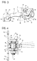
With reference to the drawings, a device for restraining
a vehicle door in a partially or fully open position is
indicated 10. The device 10 comprises a base 12,
constituted by a blanked and bent sheet-metal element
having two parallel, spaced-apart walls 14 having
respective flanges 16 in which fixing holes 18 are
formed.
A blanked sheet-metal tie-rod 20 disposed in the open
space defined between the two walls 14 is clamped between
a pair of rollers 22, 24. A first roller 22 is mounted
rotatably on a pin 26 fixed between the two walls 14 of
the base 12. The second roller 24 is mounted rotatably
on an end portion of a metal-rod torsion spring 30
carried by the base 12. The spring 30 has a first
straight portion 32 on which the roller 24 is mounted and
a second straight portion 34 which bears against the side
of an opening formed in one of the walls 14. The two
portions 32, 34 are connected to a third straight portion
36.
The tie-rod 20 has a surface 38 with a cam profile in
which a series of locating seats 40 is formed. The
surface 38 is urged against the first roller 22 by a
resilient force produced by the spring 30. This
resilient force is applied by the second roller 24 to a
surface 42 of the tie-rod 20 opposite the cam surface 38.
The tie-rod 20 can adopt various positions of stable
equilibrium relative to the base 12 according to the seat
40 engaged by the roller 22 at the time in question. The
various positions correspond to various degrees of
opening of the vehicle door.
One end of the tie-rod 20 is articulated to a fixing
support 44 constituted by a blanked and bent sheet-metal
element. The support 44 has two parallel and spaced-apart
walls 46 connected by a back portion 48. Each of
the walls 46 has a flange 50 with a fixing hole 52. The
support 44 carries an articulation element 54 having a
head 56, a spherical portion 58, and a threaded shank 60.
Beneath the head 56, the articulation element 54 has a
knurled portion 62 which is driven into a hole 64 in one
of the walls 46. A nut 61 engages the threaded shank 60
and restrains the articulation element 54 in the base 12
axially.
The spherical portion 58 of the articulation element 54
engages a bush 64 of plastics material which is fixed in
a hole 66 in the tie-rod 20. The bush 64 has two
flanges 68 which engage opposed flat surfaces of the tie-rod
20. One of the two flanges 68 is formed by hot-heading
of the bush after it has been inserted in the
hole 66. The bush 64 has a hole 70 which is cylindrical
in the undeformed condition. The spherical portion 58
of the articulation element 54 and the hole 70 in the
bush 64 may, according to the coupling tolerances between
these two elements, be engaged with slight clearance or
with slight interference. In both cases, the tie-rod 20
is free to perform an adjustment movement about an axis
perpendicular to the articulation axis 72. This
enables the tie-rod 20 and the fixing support 44 to be
arranged at a relative inclination of a few degrees, for
example, of the order of ±3° relative to a central
position. This adjustment capability is extremely
useful during the mounting of the device on a vehicle.
As shown in Figure 2, the fixing support 44 is intended
to be fixed to the door-frame 74 of a vehicle body,
whereas the base 12 is intended to be fixed to the door
76. Mounting is carried out by means of screws which
engage the fixing holes 18 and 52. The ability to
adjust the relative angular positions of the tie-rod 20
and the fixing support 44 compensates for the tolerances
and errors in the relative positioning of the door and
the door-frame along three axes X, Y and Z. The device
10 can thus be mounted easily, even when there are errors
of parallelism between the mounting planes, errors
between the fixing axes, or misalignments of the fixing
points along the vertical axis Z, etc.
Claims (5)
- A device for restraining a vehicle door in a partially or fully open position, comprising:characterized in that the articulation element (54) is formed so as to permit a relative pivoting movement between the tie-rod (20) and the fixing support (44) about an axis substantially perpendicular to the articulation axis (72).a tie-rod (20) with a cam profile (38) in which at least two locating seats (40) are formed,a base (12) having a pair of rollers (22, 24) which have parallel axes and are urged resiliently towards one another, and between which the tie-rod (20) is clamped, one of the rollers (22) cooperating with the seats (40) of the cam profile (38) in order to define at least a first and a second stable position of the tie-rod (20) relative to the base (12), corresponding to various degrees of opening of the door, anda fixing support (44) connected to an end of the tie-rod (20) by means of an articulation element (54) with an axis (72) substantially parallel to the axes of the rollers (22, 24),
- A device according to Claim 1, characterized in that the articulation element (54) comprises a portion (58) with a spherical profile which engages a bush (64) of plastics material fixed in a hole (66) in the tie-rod (20).
- A device according to Claim 2, characterized in that the bush (64) has a pair of flanges (68) which engage opposed flat surfaces of the tie-rod (20).
- A device according to Claim 1, characterized in that the articulation element (54) has a knurled portion (62) which is driven into a hole (66) in the support (44).
- A device according to Claim 4, characterized in that the articulation element (54) has a threaded shank (60) which is engaged by a clamping nut (61).
Priority Applications (1)
| Application Number | Priority Date | Filing Date | Title |
|---|---|---|---|
| EP96830515A EP0835976A1 (en) | 1996-10-09 | 1996-10-09 | A device for restraining a vehicle door in a partially or fully open position |
Applications Claiming Priority (1)
| Application Number | Priority Date | Filing Date | Title |
|---|---|---|---|
| EP96830515A EP0835976A1 (en) | 1996-10-09 | 1996-10-09 | A device for restraining a vehicle door in a partially or fully open position |
Publications (1)
| Publication Number | Publication Date |
|---|---|
| EP0835976A1 true EP0835976A1 (en) | 1998-04-15 |
Family
ID=8226027
Family Applications (1)
| Application Number | Title | Priority Date | Filing Date |
|---|---|---|---|
| EP96830515A Withdrawn EP0835976A1 (en) | 1996-10-09 | 1996-10-09 | A device for restraining a vehicle door in a partially or fully open position |
Country Status (1)
| Country | Link |
|---|---|
| EP (1) | EP0835976A1 (en) |
Cited By (3)
| Publication number | Priority date | Publication date | Assignee | Title |
|---|---|---|---|---|
| EP1249569A1 (en) * | 2001-04-13 | 2002-10-16 | Gammastamp S.p.A. | Shock absorbing door stop for vehicles |
| US6687953B1 (en) | 2000-10-13 | 2004-02-10 | Ventra Group Inc. | Torsion spring door check device |
| CN105102744A (en) * | 2013-04-11 | 2015-11-25 | 爱信精机株式会社 | A connection structure in which metal rods and metal connecting rods are connected by means of metal pins |
Citations (2)
| Publication number | Priority date | Publication date | Assignee | Title |
|---|---|---|---|---|
| US2715746A (en) * | 1950-03-13 | 1955-08-23 | Paul H Travis | Door check structure |
| DE29500053U1 (en) * | 1994-01-10 | 1995-02-23 | Gammastamp S.p.A., Turin, Turin/Torino | Device for holding a vehicle door in a partially or fully open position |
-
1996
- 1996-10-09 EP EP96830515A patent/EP0835976A1/en not_active Withdrawn
Patent Citations (3)
| Publication number | Priority date | Publication date | Assignee | Title |
|---|---|---|---|---|
| US2715746A (en) * | 1950-03-13 | 1955-08-23 | Paul H Travis | Door check structure |
| DE29500053U1 (en) * | 1994-01-10 | 1995-02-23 | Gammastamp S.p.A., Turin, Turin/Torino | Device for holding a vehicle door in a partially or fully open position |
| FR2714928A3 (en) | 1994-01-10 | 1995-07-13 | Gammastamp Spa | Device for holding vehicle door partially or completely open |
Cited By (4)
| Publication number | Priority date | Publication date | Assignee | Title |
|---|---|---|---|---|
| US6687953B1 (en) | 2000-10-13 | 2004-02-10 | Ventra Group Inc. | Torsion spring door check device |
| EP1249569A1 (en) * | 2001-04-13 | 2002-10-16 | Gammastamp S.p.A. | Shock absorbing door stop for vehicles |
| CN105102744A (en) * | 2013-04-11 | 2015-11-25 | 爱信精机株式会社 | A connection structure in which metal rods and metal connecting rods are connected by means of metal pins |
| EP2985400A4 (en) * | 2013-04-11 | 2016-06-29 | Aisin Seiki | BOND STRUCTURE HAVING A METAL PIN BETWEEN A METAL BOND AND A METAL LEVER |
Similar Documents
| Publication | Publication Date | Title |
|---|---|---|
| US4720895A (en) | Quick-disconnect door hinge | |
| US4807331A (en) | Door lift-off hinge | |
| US4864687A (en) | Three piece lift-off door hinge | |
| CA2035121C (en) | Adjustable steering column mechanism | |
| US6581969B2 (en) | Buckle device | |
| US5392493A (en) | Pocket hinge assembly | |
| US6266848B1 (en) | Hinge | |
| JP3487397B2 (en) | Thermal recording device | |
| JPH10157634A (en) | Device to regulate longitudinal direction and/or height or inclination of steering column for automobile | |
| JP3795934B2 (en) | Door hinge for automobile door | |
| US4546668A (en) | Position adjustment device | |
| US6622343B2 (en) | Hinge for furniture | |
| US20020073509A1 (en) | Mechanism and method for adjusting doors | |
| US5499851A (en) | Outside door handle attaching bracket arrangement | |
| EP0539206A1 (en) | Hinge | |
| EP0315184B1 (en) | Adjustable shoulder anchor mechanism | |
| JPH09118139A (en) | Battery frame for electric vehicles | |
| US5524324A (en) | Door hinge with an integrated locking device | |
| PT1070188E (en) | DOOR STOP FOR AUTOMOTIVE VEHICLE | |
| US9809134B2 (en) | Automatically aligning latching arrangement | |
| US6418603B1 (en) | Margin blade holder assembly | |
| US12398587B1 (en) | Window hinge assembly and methods | |
| EP0060362A1 (en) | Adjustable rear view mirrors | |
| EP0109136B1 (en) | Door checks | |
| US20010003701A1 (en) | Cam micro-finishing tool |
Legal Events
| Date | Code | Title | Description |
|---|---|---|---|
| PUAI | Public reference made under article 153(3) epc to a published international application that has entered the european phase |
Free format text: ORIGINAL CODE: 0009012 |
|
| AK | Designated contracting states |
Kind code of ref document: A1 Designated state(s): AT BE CH DE DK ES FI FR GB GR IE IT LI LU MC NL PT SE |
|
| AX | Request for extension of the european patent |
Free format text: AL;LT;LV;SI |
|
| AKX | Designation fees paid | ||
| RBV | Designated contracting states (corrected) | ||
| STAA | Information on the status of an ep patent application or granted ep patent |
Free format text: STATUS: THE APPLICATION IS DEEMED TO BE WITHDRAWN |
|
| 18D | Application deemed to be withdrawn |
Effective date: 19981016 |