EP0835847A1 - Machine for cutting laminated glass plates - Google Patents
Machine for cutting laminated glass plates Download PDFInfo
- Publication number
- EP0835847A1 EP0835847A1 EP97117525A EP97117525A EP0835847A1 EP 0835847 A1 EP0835847 A1 EP 0835847A1 EP 97117525 A EP97117525 A EP 97117525A EP 97117525 A EP97117525 A EP 97117525A EP 0835847 A1 EP0835847 A1 EP 0835847A1
- Authority
- EP
- European Patent Office
- Prior art keywords
- machine
- glass
- fact
- cut
- membrane
- Prior art date
- Legal status (The legal status is an assumption and is not a legal conclusion. Google has not performed a legal analysis and makes no representation as to the accuracy of the status listed.)
- Granted
Links
- 239000005340 laminated glass Substances 0.000 title claims abstract description 17
- 238000005520 cutting process Methods 0.000 title claims description 23
- 239000011521 glass Substances 0.000 claims abstract description 53
- 239000012528 membrane Substances 0.000 claims abstract description 35
- 238000000926 separation method Methods 0.000 claims abstract description 24
- 238000000034 method Methods 0.000 claims description 37
- 230000008569 process Effects 0.000 claims description 16
- 230000009471 action Effects 0.000 claims description 11
- 239000000470 constituent Substances 0.000 claims description 6
- 238000010438 heat treatment Methods 0.000 claims description 3
- 230000006835 compression Effects 0.000 claims 1
- 238000007906 compression Methods 0.000 claims 1
- 239000005344 low-emissivity glass Substances 0.000 claims 1
- 230000005855 radiation Effects 0.000 claims 1
- 230000000694 effects Effects 0.000 description 7
- 238000004519 manufacturing process Methods 0.000 description 6
- 239000002245 particle Substances 0.000 description 5
- 230000007246 mechanism Effects 0.000 description 4
- XLYOFNOQVPJJNP-UHFFFAOYSA-N water Substances O XLYOFNOQVPJJNP-UHFFFAOYSA-N 0.000 description 4
- 229920002554 vinyl polymer Polymers 0.000 description 3
- 230000008901 benefit Effects 0.000 description 2
- 229910003460 diamond Inorganic materials 0.000 description 2
- 239000010432 diamond Substances 0.000 description 2
- 239000000463 material Substances 0.000 description 2
- 239000002699 waste material Substances 0.000 description 2
- 239000002351 wastewater Substances 0.000 description 2
- 230000003466 anti-cipated effect Effects 0.000 description 1
- 238000005452 bending Methods 0.000 description 1
- 230000005540 biological transmission Effects 0.000 description 1
- 238000001816 cooling Methods 0.000 description 1
- 230000002950 deficient Effects 0.000 description 1
- 238000001035 drying Methods 0.000 description 1
- 230000004927 fusion Effects 0.000 description 1
- 230000003993 interaction Effects 0.000 description 1
- 230000002427 irreversible effect Effects 0.000 description 1
- 238000012423 maintenance Methods 0.000 description 1
- 238000005457 optimization Methods 0.000 description 1
- 229920003023 plastic Polymers 0.000 description 1
- 238000003825 pressing Methods 0.000 description 1
- 230000000750 progressive effect Effects 0.000 description 1
- 230000009467 reduction Effects 0.000 description 1
- 238000006467 substitution reaction Methods 0.000 description 1
- 238000005406 washing Methods 0.000 description 1
Images


Classifications
-
- C—CHEMISTRY; METALLURGY
- C03—GLASS; MINERAL OR SLAG WOOL
- C03B—MANUFACTURE, SHAPING, OR SUPPLEMENTARY PROCESSES
- C03B33/00—Severing cooled glass
- C03B33/07—Cutting armoured, multi-layered, coated or laminated, glass products
- C03B33/076—Laminated glass comprising interlayers
- C03B33/078—Polymeric interlayers
-
- C—CHEMISTRY; METALLURGY
- C03—GLASS; MINERAL OR SLAG WOOL
- C03B—MANUFACTURE, SHAPING, OR SUPPLEMENTARY PROCESSES
- C03B33/00—Severing cooled glass
- C03B33/02—Cutting or splitting sheet glass or ribbons; Apparatus or machines therefor
- C03B33/0207—Cutting or splitting sheet glass or ribbons; Apparatus or machines therefor the sheet being in a substantially vertical plane
Definitions
- the main scope of the present application is therefore that to resolve the underlined technical problems eliminating the inconveniences relevant to the known technique and therefore contriving a procedure that allows to obtain in automatic or semiautomatic way the cut of a plate of laminated glass, for the splitting into subsections , generally rectangular but not excluding, even if with great complications, also the polygonal forms and, in a semiautomatic variation the shaped forms as well.
- the all with an automatic procedure or semiautomatic procedure in the versions of polygonal cutting and shaped cutting that results economic, that improves the quality of the cut in respect to that obtainable with the known technique and that reduces the occupation of area of the establishment sensitively for this process of cutting.
- the polyvinyl which unites in irreversible way the two plates of glass to constitute a "multilayer” that acquires so elevated mechanical characteristics like the greatest moment of inertia and modulus of resistance to bending and insuperable characteristics of resistance to the breakthrough in as the brittleness of the glass, even if remaining a characteristic of the single plate, is compensated by the notable elastic resistance of the intimately interposed membrane (it' s enough to think about the employment, in the three-dimensional version, in the automotive sector).
- the single plates of glass in the most diffused solutions, have a thickness of 3 or 4 or 5 or 6 mm, while the membrane of polyvinyl is obtained using one or more sheets (max 4) whose single thickness is of 0.38 mm.
- the process of manufacture that unites intimately both the plates and the membrane, consists in the principal followings but not exclusive phases: washing and drying of the single plates, layout of the sheet or the sheets of polyvinyil in horizontal order on the inferior plate, laying of the superior plate, pressing of the whole sheet - membrane - sheet on an horizontal press, heated rollers type, final treatment in autoclave to elevated temperature (during which the membrane is transformed from opaque to transparent).
- This process is applied actually typically to the maximum dimensions of the glass stratified of 6000 mm x 3210 mm, and the today's tendency is of to use the most possible this maximum format in how much logically the plate is great and great anymore it is the optimization of the wastes due to the following process of cutting.
- the exigency to cut the big plate of laminated glass is not limited to the case of the production of the plates for to employ in the final use, for example in the window or in the showcase, but also includes the case of the subdivision of the big plate, as obtained by the primary process of production, into subsections, or for limitations due to the transport or to the employment in small glassworks or for necessity to eliminate possible defective zones of the same big plate saving the remainder parts that fulfil the quality standards required by the buyer.
- the Figure 1 shows the product that is processed in the machine object of the present application, that is the big plate of glass, with an example tracing of the subdivision in the in plates requested for the following employment. It is pointed out with x the first level of cut, y the second, z third etc., clearly the passage to the following level of cut involves the rotation of the interested strip of the plate and its translation both from the zone of cut to that of rotation and the following translation from the zone of rotation to the preceding bridge of cut or to a following bridge of cut, in the case the machine has more than one bridge of cut.
- the nucleus of the inventive content resides in the particular conformation of the FIXED BRIDGE, not more incorporating the three operations of incision / breaking / separation in an only station on the contrary carrying out the three operations in at least two substations and besides in the concept of having "verticalized” and automatized the procedure of cut of the plates of glass, avoiding so and the intervention of the operator and the manipulation of the plate of departure and the plates obtained with the cut that remain therefore ALWAYS IN VERTICAL POSITION, from the arrival of the base material to the delivery of the ended product (for example the panel of insulating glass).
- the innovative aspect concerns the sector where it happens the drawing of the membrane as, unlike the machines of which to the known technique, it' s not constituted by two separate beams on the contrary by beams opportunely united transversally in such a way to make the drawing uniform and precise in the whole field of action. Enormous advantages are achieved both from the ergonomic point of view and safety and occupation of space and quality.
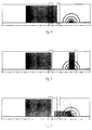
- the Figure 2 represents the big plate in its position of loading on the station of feeding of the cutting table.
- the Figure 3 represents the positioning of the big plate (that then is repeated for the following portions of the same big plate) in way to bring the vertical line destined to be cut in correspondence of the substation of incision and breaking.
- the desired dimension is determined by the position of the mobile bridge, and of the relative reference of contrast with the glass; the mobile bridge also serves to the following clamping and translation of the strip if this last has such dimensions from not to be transportable for the alone action of the conveyor working in correspondence of the inferior edge of the same one.
- the Figure 4 represents the positioning of the big plate (that then is repeated for the following portions of the same big plate) in way to bring the vertical line, already engraved and broken in the preceding substation, in correspondence of the substation of separation of the membrane. In this way a cut (in its complete meaning) of level x has been carried out.
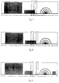
- the Figure 5 represents the strip, previously cut, translated through the mobile bridge and of the relative clamps in correspondence of the station of rotation.
- the Figure 6 represents the rotation of the same strip and the contemporary translation of the mobile bridge to the purpose of his anticipated positioning of measure of the dimension of the following cut.
- the Figure 7 represents the positioning of the strip (that then is repeated for the following portions of the same strip) in way to bring the vertical line destined to be cut in correspondence of the substation of incision and breaking.
- the Figure 8 represents the positioning of the strip (that then is repeated for the following portions of the same strip) in way to bring the vertical line, already engraved and broken in the preceding substation, in correspondence of the substation of separation of the membrane (operation not effectuated in the case of monolithic glass, that is non-laminated . In this way a cut (in its complete meaning) of level y has been carried out.
- the Figure 9 represents the first ended piece (obtained through two levels of cut x and y) translated in the station of unloading of the machine and destined to the following processes.
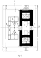
- the Figure 10 represents, in section, a possible conformation of the station of cutting, divided in the substation of incision and breaking and in the substation of separation of the membrane (this doesn't exclude the constructive solution with three separate substations, respectively of incision, breaking and membrane separation).
- the passage from the sub-process of incision and breaking to the sub-process of membrane separation happens through opening of the group of main beams and cantilevered beam, with consequent relaxation of the pads of block of the glass and through translation of the glass in way to move the line interested by the process from the axis 3 to the axis 4.
- the movements of opening and closing of the beams happen through pneumatic or hydraulic or electric driving (not represented as known technique) but combined with mechanical devices, for example of the type of trees of torsion 5 terminating with gears 6 that interact with tooth rails 7, with the purpose to obtain a regular and precise movement.
- With 8 ' and 8'' are pointed out the opposed carriages containing the tools of incision and breaking.
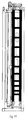
- the Figure 11 represents a frontal longitudinal sight of the fixed bridge, in which the components described in the preceding figure are easily identifiable.
- the Figure 12 represents the constructive details of the opposed carriages 8 ' and 8'' with identification of the respective turrets of incision 11' and 11'' and of the turrets of breaking12 ' and 12'' (hidden from the turrets of incision). More in the detail every turret of incision is composed by a small wheel of incision 13, relative tool-holder14 and adjustable mechanism, for example by means of a spring , of balancing of the strength of incision; the same turret is translatable, as connected to the carriage 8, in the direction of cutting, along the guides 15 through, for example, an electric driving and a belt transmission; the two turrets of incision act contemporarily and contrasted against the glass.
- Every turret of breaking is composed by a small wheel of contrast 16 that presses on the glass and from a tool-holder 17, fixed on the carriage 8 that therefore makes the turret of breakage translatable in the direction of cutting along the guides 15; the two turrets of breaking act contrasted on the glass but in following phases.
Landscapes
- Chemical & Material Sciences (AREA)
- Engineering & Computer Science (AREA)
- Materials Engineering (AREA)
- Organic Chemistry (AREA)
- Re-Forming, After-Treatment, Cutting And Transporting Of Glass Products (AREA)
- Joining Of Glass To Other Materials (AREA)
Abstract
Description
This machine is inconvenient for the cut of the laminated mono-membrane glass, both for the modest speed of the process and for the elevated cost of the machinery due to the necessity to employ high pressure pumps. Only advantage, not allowed by other existing machines and by the machine object of the present application (except one her semiautomatic variation), is constituted by the possibility to effect the shaped cutting. Also this process, employing water for the principle of job, involves onerous problems of treatment and disposal of the waste water containing abrasive particles and particles of glass.
Enormous advantages are achieved both from the ergonomic point of view and safety and occupation of space and quality.
The movements of opening and closing of the beams happen through pneumatic or hydraulic or electric driving (not represented as known technique) but combined with mechanical devices, for example of the type of trees of
With 8 ' and 8'' are pointed out the opposed carriages containing the tools of incision and breaking. With 9 ' and 9'' the means are pointed out for the heating of the membrane that is effectuated in combination with the drawing of the same, obtained by the movement in the direction of the
Claims (16)
- machine for the cutting of the laminated glass constituted by a table preferentially with a vertical disposition or slightly tilted in respect to the vertical one where the process of cutting happens for incision breaking of the glass and separation of the membrane in a station said of cutting, the separation of the membrane happening for single action or composed by systems of drawing / heating / radiation / mechanic cut
characterized by the fact what the structure to obtain the drawing of the two parts of the plate to be separated is constituted by two contrasted bridges each one realized with an only beam having transversal section, composed by more elements, to global form essentially of U in such way that the pads for clamping and drawing of the plate are reciprocally opposed and act directly their strength of drawing directly on the glass elements eliminating so the deformation of the structure in the direction of the drawing. - machine as to the claim 1 characterized by the fact to have, besides the principal beam conformed to U, one or more other secondary beams destined, alone or in combination with the principal beam, to the other phases of the process of cut of the laminated glass like the incision and the breaking.
- machine as to the claims 1 and 2 characterized by the fact that the devices of drawing, so-called pads, they are hinged at notable distance from the surface of the glass in such a way that from the combination of the same distance with the form of the same pad an action of increase of the strengths of compression and drawing can be obtained.
- machine as to the claims 1 and 2 characterized by the fact that the action of heating of the membrane is obtained with a system of radiant lamps whose action has focused, through a reflector having special shape, on the membrane.
- machine as to the claim 4 characterized by the fact that the lamps are lying or in line on a same side in respect to the glass or alternate on the opposite sides in respect to the glass.
- machine as to the claim 4 characterized by the fact that the lamps that enter in action are only those interested by the encumbrance of the glass.
- machine as to the claim 4 characterized by the fact that, in alternative to the lamps, the separation of the membrane is obtained with mechanic or electronic or combined means.
- machine as to the claims 1 and 2 characterized by the fact that, through an opportune orientation of the conveyor of transport and support of the glass, or through an orientation of the bridge of cut, or through an action combined of such orientations, inclined cuts are obtained.
- machine as to the claims 1 and 2 characterized by the fact that, through an opportune action and of the tool of incision and the motion of the glass, it is possible to get shaped incisions, in this event the breaking of the glass and the separation of the membrane are subsequently carried out or manually or on other machine.
- machine as to the claims 1 and 2 characterized by the fact that, through an opportune action both of the tool of incision and of the bridge of cut, made mobile, it is possible to get shaped incisions, in this event the breaking of the glass and the separation of the membrane are subsequently carried out or manually or on other machine.
- machine as to the claims 1 and 2 characterized by the fact to have one or more ulterior bridges of cutting.
- machine as to the claims 1 and 2 characterized by the fact to include, in the bridge of cutting either separately or together with the other zones of incision / breaking / separation, also a section for the surface grinding of the low emissivity glass.
- machine as to the claims 1 and 2 characterized by the fact that the motion of the principal and secondary beams constituent the opposed bridges, is obtained through pneumatic or hydraulic or electric driving combined with mechanical bonds, for (non the only) example of the type with trees of torsion, gearwheels and tooth rail, with the purpose to obtain a regular and precise motion.
- machine as to the claims 1 and 2 characterized by the fact that the group of beams constituent the part of the bridge in line with the back of the slide conveyor of the glass withdraws to the passage of the glass slightly in way to eliminate the minimum possibility of interference with the pads.
- machine as to the claims 1 and 2 characterized by the fact that the tool of incision is lubricated during the phase of job.
- machine as to the claims 1 and 2 characterized by the fact that it can also operate the cut on monolithic glass (that is without membrane), in this case the phase of breaking of the membrane is missing (and eventually the relative device).
Priority Applications (1)
| Application Number | Priority Date | Filing Date | Title |
|---|---|---|---|
| SI9730693T SI0835847T1 (en) | 1996-10-14 | 1997-10-10 | Machine for cutting laminated glass plates |
Applications Claiming Priority (2)
| Application Number | Priority Date | Filing Date | Title |
|---|---|---|---|
| IT96TV000128A IT1288673B1 (en) | 1996-10-14 | 1996-10-14 | LAMINATED GLASS CUTTING MACHINE |
| ITTV960128 | 1996-10-14 |
Publications (2)
| Publication Number | Publication Date |
|---|---|
| EP0835847A1 true EP0835847A1 (en) | 1998-04-15 |
| EP0835847B1 EP0835847B1 (en) | 2005-01-05 |
Family
ID=11420007
Family Applications (1)
| Application Number | Title | Priority Date | Filing Date |
|---|---|---|---|
| EP97117525A Expired - Lifetime EP0835847B1 (en) | 1996-10-14 | 1997-10-10 | Machine for cutting laminated glass plates |
Country Status (6)
| Country | Link |
|---|---|
| EP (1) | EP0835847B1 (en) |
| AT (1) | ATE286490T1 (en) |
| DE (1) | DE69732167T2 (en) |
| ES (1) | ES2233988T3 (en) |
| IT (1) | IT1288673B1 (en) |
| SI (1) | SI0835847T1 (en) |
Cited By (5)
| Publication number | Priority date | Publication date | Assignee | Title |
|---|---|---|---|---|
| EP1323681A3 (en) * | 2001-12-24 | 2004-06-16 | HEGLA Fahrzeug- u. Maschinenbau GmbH & Co. KG | Process and apparatus to cut laminated glass |
| EP1314703A3 (en) * | 2001-11-26 | 2004-06-30 | HEGLA Fahrzeug- u. Maschinenbau GmbH & Co. KG | Apparatus to cut laminated glass |
| EP1574484A3 (en) * | 2004-03-11 | 2006-02-01 | BOTTERO S.p.A. | Method of cutting and parting sheets of glass, and vertical apparatus implementing such a method |
| EP1623962A1 (en) * | 2004-08-03 | 2006-02-08 | BOTTERO S.p.A. | Method of cutting and parting vertical sheets, and vertical apparatus implementing such method |
| WO2015117172A1 (en) | 2014-02-10 | 2015-08-13 | Lisec Austria Gmbh | Method for cutting laminated glass |
Citations (7)
| Publication number | Priority date | Publication date | Assignee | Title |
|---|---|---|---|---|
| FR2375041A1 (en) * | 1976-12-20 | 1978-07-21 | Bottero Spa | Cutting glass panes to size - using a machine which scores both sides of panel and then applies a breaking load |
| AU603937B2 (en) * | 1987-11-10 | 1990-11-29 | Glass Engineering Pty. Ltd. | Glass cutting apparatus |
| EP0503647A2 (en) * | 1991-03-15 | 1992-09-16 | BOTTERO S.p.A. | Method for cutting a laminated glass sheet along predetermined lines |
| EP0564758A1 (en) * | 1992-04-06 | 1993-10-13 | Peter Lisec | Method and apparatus for dividing glass sheets into parts |
| DE4234536A1 (en) * | 1992-10-14 | 1994-04-21 | Armatec Arnold Maschinentechni | Cutting equipment esp. for vertical laminated safety glass - has manipulator with controller esp. for pane positioning located at cutting, breaking and sepg. device |
| EP0596852A1 (en) * | 1992-11-02 | 1994-05-11 | Peter Lisec | Method and apparatus for cutting laminated glass |
| DE29608724U1 (en) * | 1996-05-14 | 1997-06-26 | Hegla Fahrzeug- Und Maschinenbau Gmbh & Co Kg, 37688 Beverungen | Device for separating glass sheets |
-
1996
- 1996-10-14 IT IT96TV000128A patent/IT1288673B1/en active IP Right Grant
-
1997
- 1997-10-10 AT AT97117525T patent/ATE286490T1/en active
- 1997-10-10 DE DE69732167T patent/DE69732167T2/en not_active Expired - Lifetime
- 1997-10-10 SI SI9730693T patent/SI0835847T1/en unknown
- 1997-10-10 EP EP97117525A patent/EP0835847B1/en not_active Expired - Lifetime
- 1997-10-10 ES ES97117525T patent/ES2233988T3/en not_active Expired - Lifetime
Patent Citations (7)
| Publication number | Priority date | Publication date | Assignee | Title |
|---|---|---|---|---|
| FR2375041A1 (en) * | 1976-12-20 | 1978-07-21 | Bottero Spa | Cutting glass panes to size - using a machine which scores both sides of panel and then applies a breaking load |
| AU603937B2 (en) * | 1987-11-10 | 1990-11-29 | Glass Engineering Pty. Ltd. | Glass cutting apparatus |
| EP0503647A2 (en) * | 1991-03-15 | 1992-09-16 | BOTTERO S.p.A. | Method for cutting a laminated glass sheet along predetermined lines |
| EP0564758A1 (en) * | 1992-04-06 | 1993-10-13 | Peter Lisec | Method and apparatus for dividing glass sheets into parts |
| DE4234536A1 (en) * | 1992-10-14 | 1994-04-21 | Armatec Arnold Maschinentechni | Cutting equipment esp. for vertical laminated safety glass - has manipulator with controller esp. for pane positioning located at cutting, breaking and sepg. device |
| EP0596852A1 (en) * | 1992-11-02 | 1994-05-11 | Peter Lisec | Method and apparatus for cutting laminated glass |
| DE29608724U1 (en) * | 1996-05-14 | 1997-06-26 | Hegla Fahrzeug- Und Maschinenbau Gmbh & Co Kg, 37688 Beverungen | Device for separating glass sheets |
Cited By (7)
| Publication number | Priority date | Publication date | Assignee | Title |
|---|---|---|---|---|
| EP1314703A3 (en) * | 2001-11-26 | 2004-06-30 | HEGLA Fahrzeug- u. Maschinenbau GmbH & Co. KG | Apparatus to cut laminated glass |
| EP1577273A3 (en) * | 2001-11-26 | 2005-11-30 | HEGLA GmbH & Co. KG | Apparatus and method for cutting laminated glass along a desired contour |
| EP1752425A1 (en) * | 2001-11-26 | 2007-02-14 | HEGLA GmbH & Co. KG | Apparatus to cut laminated glass and method for positioning laminated glass to be cut |
| EP1323681A3 (en) * | 2001-12-24 | 2004-06-16 | HEGLA Fahrzeug- u. Maschinenbau GmbH & Co. KG | Process and apparatus to cut laminated glass |
| EP1574484A3 (en) * | 2004-03-11 | 2006-02-01 | BOTTERO S.p.A. | Method of cutting and parting sheets of glass, and vertical apparatus implementing such a method |
| EP1623962A1 (en) * | 2004-08-03 | 2006-02-08 | BOTTERO S.p.A. | Method of cutting and parting vertical sheets, and vertical apparatus implementing such method |
| WO2015117172A1 (en) | 2014-02-10 | 2015-08-13 | Lisec Austria Gmbh | Method for cutting laminated glass |
Also Published As
| Publication number | Publication date |
|---|---|
| DE69732167D1 (en) | 2005-02-10 |
| ES2233988T3 (en) | 2005-06-16 |
| SI0835847T1 (en) | 2005-06-30 |
| ITTV960128A1 (en) | 1998-04-14 |
| DE69732167T2 (en) | 2005-12-08 |
| IT1288673B1 (en) | 1998-09-23 |
| ATE286490T1 (en) | 2005-01-15 |
| EP0835847B1 (en) | 2005-01-05 |
| ITTV960128A0 (en) | 1996-10-14 |
Similar Documents
| Publication | Publication Date | Title |
|---|---|---|
| CN210997114U (en) | Coil stock cutting device for laser cutting machine | |
| US4736661A (en) | Cutting apparatus | |
| GB2473107A (en) | Grinding cylindrical and curved contours especially on crankshafts | |
| EP0835847A1 (en) | Machine for cutting laminated glass plates | |
| EP2316797B1 (en) | Machine and method for performing cutting operations on a multi-layered glass sheet along a predermined path | |
| JPH09510147A (en) | Edge bonding device with milling device | |
| CN115635322B (en) | Automatic wedge-shaped cushion block machining system and machining method | |
| EP0834479A1 (en) | Process for cutting of glass sheets, standard, laminated not armored | |
| CN216576215U (en) | Steel band butt welding platform | |
| CN201136084Y (en) | Laser welding device | |
| CN220093424U (en) | Laser cutting machine with clamping function | |
| EP0837040A1 (en) | Method and machine for automatic cutting of laminated glass and armored glass | |
| CN215327747U (en) | Non-contact cambered surface glass cutting equipment | |
| CN215825440U (en) | Full-automatic stock cutter | |
| CN120269156B (en) | Automatic shearing butt welding machine | |
| CN221516570U (en) | Novel vertical three-dimensional laser cutting machine of simple and convenient clamping | |
| CN223685748U (en) | Triaxial trompil machining center | |
| CN213857639U (en) | Laser antenna laser machine | |
| CN216541397U (en) | Automatic code carving equipment | |
| CN216632790U (en) | Arc cutting device of metal show shelf processing usefulness | |
| CN211759274U (en) | Laser cutting machine | |
| CN213317381U (en) | Galvanized wire cutting device | |
| CN215240057U (en) | Grinding machine capable of precisely sawing steel plate | |
| CN214684740U (en) | Automatic unloading laser pipe cutting machine of going up of three chucks | |
| CN210703273U (en) | Large-breadth crack-free wear-resisting plate surfacing device |
Legal Events
| Date | Code | Title | Description |
|---|---|---|---|
| PUAI | Public reference made under article 153(3) epc to a published international application that has entered the european phase |
Free format text: ORIGINAL CODE: 0009012 |
|
| AK | Designated contracting states |
Kind code of ref document: A1 Designated state(s): AT DE ES FR GB |
|
| AX | Request for extension of the european patent |
Free format text: SI |
|
| 17P | Request for examination filed |
Effective date: 19981012 |
|
| AKX | Designation fees paid |
Free format text: AT DE ES FR GB |
|
| AXX | Extension fees paid |
Free format text: SI PAYMENT 981012 |
|
| RBV | Designated contracting states (corrected) |
Designated state(s): AT DE ES FR GB |
|
| 17Q | First examination report despatched |
Effective date: 20010424 |
|
| GRAP | Despatch of communication of intention to grant a patent |
Free format text: ORIGINAL CODE: EPIDOSNIGR1 |
|
| GRAS | Grant fee paid |
Free format text: ORIGINAL CODE: EPIDOSNIGR3 |
|
| GRAA | (expected) grant |
Free format text: ORIGINAL CODE: 0009210 |
|
| AK | Designated contracting states |
Kind code of ref document: B1 Designated state(s): AT DE ES FR GB |
|
| AX | Request for extension of the european patent |
Extension state: SI |
|
| REG | Reference to a national code |
Ref country code: GB Ref legal event code: FG4D |
|
| REF | Corresponds to: |
Ref document number: 69732167 Country of ref document: DE Date of ref document: 20050210 Kind code of ref document: P |
|
| REG | Reference to a national code |
Ref country code: ES Ref legal event code: FG2A Ref document number: 2233988 Country of ref document: ES Kind code of ref document: T3 |
|
| PLBE | No opposition filed within time limit |
Free format text: ORIGINAL CODE: 0009261 |
|
| STAA | Information on the status of an ep patent application or granted ep patent |
Free format text: STATUS: NO OPPOSITION FILED WITHIN TIME LIMIT |
|
| 26N | No opposition filed |
Effective date: 20051006 |
|
| ET | Fr: translation filed | ||
| REG | Reference to a national code |
Ref country code: GB Ref legal event code: FG4D |
|
| REG | Reference to a national code |
Ref country code: SI Ref legal event code: KO00 Effective date: 20090605 |
|
| PGFP | Annual fee paid to national office [announced via postgrant information from national office to epo] |
Ref country code: ES Payment date: 20100913 Year of fee payment: 14 |
|
| PGFP | Annual fee paid to national office [announced via postgrant information from national office to epo] |
Ref country code: GB Payment date: 20100916 Year of fee payment: 14 |
|
| PGFP | Annual fee paid to national office [announced via postgrant information from national office to epo] |
Ref country code: FR Payment date: 20101014 Year of fee payment: 14 Ref country code: AT Payment date: 20101027 Year of fee payment: 14 |
|
| GBPC | Gb: european patent ceased through non-payment of renewal fee |
Effective date: 20111010 |
|
| REG | Reference to a national code |
Ref country code: FR Ref legal event code: ST Effective date: 20120629 |
|
| PG25 | Lapsed in a contracting state [announced via postgrant information from national office to epo] |
Ref country code: GB Free format text: LAPSE BECAUSE OF NON-PAYMENT OF DUE FEES Effective date: 20111010 Ref country code: FR Free format text: LAPSE BECAUSE OF NON-PAYMENT OF DUE FEES Effective date: 20111102 |
|
| REG | Reference to a national code |
Ref country code: ES Ref legal event code: FD2A Effective date: 20130605 |
|
| REG | Reference to a national code |
Ref country code: AT Ref legal event code: MM01 Ref document number: 286490 Country of ref document: AT Kind code of ref document: T Effective date: 20121010 |
|
| PG25 | Lapsed in a contracting state [announced via postgrant information from national office to epo] |
Ref country code: AT Free format text: LAPSE BECAUSE OF NON-PAYMENT OF DUE FEES Effective date: 20121010 |
|
| PG25 | Lapsed in a contracting state [announced via postgrant information from national office to epo] |
Ref country code: ES Free format text: LAPSE BECAUSE OF NON-PAYMENT OF DUE FEES Effective date: 20111011 |
|
| REG | Reference to a national code |
Ref country code: DE Ref legal event code: R082 Ref document number: 69732167 Country of ref document: DE Representative=s name: SCHAUMBURG UND PARTNER PATENTANWAELTE MBB, DE Ref country code: DE Ref legal event code: R082 Ref document number: 69732167 Country of ref document: DE Representative=s name: SCHAUMBURG & PARTNER PATENTANWAELTE MBB, DE Ref country code: DE Ref legal event code: R082 Ref document number: 69732167 Country of ref document: DE Representative=s name: SCHAUMBURG & PARTNER PATENTANWAELTE GBR, DE |
|
| PGFP | Annual fee paid to national office [announced via postgrant information from national office to epo] |
Ref country code: DE Payment date: 20151124 Year of fee payment: 19 |
|
| REG | Reference to a national code |
Ref country code: DE Ref legal event code: R119 Ref document number: 69732167 Country of ref document: DE |
|
| PG25 | Lapsed in a contracting state [announced via postgrant information from national office to epo] |
Ref country code: DE Free format text: LAPSE BECAUSE OF NON-PAYMENT OF DUE FEES Effective date: 20170503 |