EP0835679A1 - Method for the concentration of liquid mixtures - Google Patents
Method for the concentration of liquid mixtures Download PDFInfo
- Publication number
- EP0835679A1 EP0835679A1 EP97203081A EP97203081A EP0835679A1 EP 0835679 A1 EP0835679 A1 EP 0835679A1 EP 97203081 A EP97203081 A EP 97203081A EP 97203081 A EP97203081 A EP 97203081A EP 0835679 A1 EP0835679 A1 EP 0835679A1
- Authority
- EP
- European Patent Office
- Prior art keywords
- liquid mixture
- concentrator
- turbo
- stream
- concentration
- Prior art date
- Legal status (The legal status is an assumption and is not a legal conclusion. Google has not performed a legal analysis and makes no representation as to the accuracy of the status listed.)
- Granted
Links
- 239000000203 mixture Substances 0.000 title claims abstract description 42
- 239000007788 liquid Substances 0.000 title claims abstract description 41
- 238000000034 method Methods 0.000 title claims abstract description 16
- 238000010438 heat treatment Methods 0.000 claims abstract description 9
- 238000007599 discharging Methods 0.000 claims description 2
- 238000011144 upstream manufacturing Methods 0.000 claims description 2
- 239000012467 final product Substances 0.000 claims 1
- 239000000243 solution Substances 0.000 description 8
- 239000007787 solid Substances 0.000 description 5
- QTBSBXVTEAMEQO-UHFFFAOYSA-N Acetic acid Chemical compound CC(O)=O QTBSBXVTEAMEQO-UHFFFAOYSA-N 0.000 description 3
- YMWUJEATGCHHMB-UHFFFAOYSA-N Dichloromethane Chemical compound ClCCl YMWUJEATGCHHMB-UHFFFAOYSA-N 0.000 description 3
- 238000005516 engineering process Methods 0.000 description 2
- 238000012423 maintenance Methods 0.000 description 2
- 238000003860 storage Methods 0.000 description 2
- XLYOFNOQVPJJNP-UHFFFAOYSA-N water Substances O XLYOFNOQVPJJNP-UHFFFAOYSA-N 0.000 description 2
- FBPFZTCFMRRESA-FSIIMWSLSA-N D-Glucitol Natural products OC[C@H](O)[C@H](O)[C@@H](O)[C@H](O)CO FBPFZTCFMRRESA-FSIIMWSLSA-N 0.000 description 1
- FAPWRFPIFSIZLT-UHFFFAOYSA-M Sodium chloride Chemical compound [Na+].[Cl-] FAPWRFPIFSIZLT-UHFFFAOYSA-M 0.000 description 1
- 229920002472 Starch Polymers 0.000 description 1
- 230000021736 acetylation Effects 0.000 description 1
- 238000006640 acetylation reaction Methods 0.000 description 1
- 239000007864 aqueous solution Substances 0.000 description 1
- 230000015572 biosynthetic process Effects 0.000 description 1
- 238000004140 cleaning Methods 0.000 description 1
- 230000003247 decreasing effect Effects 0.000 description 1
- 239000000835 fiber Substances 0.000 description 1
- 239000012530 fluid Substances 0.000 description 1
- 235000013305 food Nutrition 0.000 description 1
- 229910001385 heavy metal Inorganic materials 0.000 description 1
- 238000004519 manufacturing process Methods 0.000 description 1
- 239000012528 membrane Substances 0.000 description 1
- -1 polypropylene carbonate Polymers 0.000 description 1
- 229920000379 polypropylene carbonate Polymers 0.000 description 1
- 238000000746 purification Methods 0.000 description 1
- 238000011084 recovery Methods 0.000 description 1
- 238000004064 recycling Methods 0.000 description 1
- 150000003839 salts Chemical class 0.000 description 1
- 239000000600 sorbitol Substances 0.000 description 1
- 235000019698 starch Nutrition 0.000 description 1
- 239000008107 starch Substances 0.000 description 1
- 239000002699 waste material Substances 0.000 description 1
Images
Classifications
-
- B—PERFORMING OPERATIONS; TRANSPORTING
- B01—PHYSICAL OR CHEMICAL PROCESSES OR APPARATUS IN GENERAL
- B01D—SEPARATION
- B01D1/00—Evaporating
- B01D1/22—Evaporating by bringing a thin layer of the liquid into contact with a heated surface
- B01D1/222—In rotating vessels; vessels with movable parts
- B01D1/228—In rotating vessels; vessels with movable parts horizontally placed cylindrical container or drum
-
- Y—GENERAL TAGGING OF NEW TECHNOLOGICAL DEVELOPMENTS; GENERAL TAGGING OF CROSS-SECTIONAL TECHNOLOGIES SPANNING OVER SEVERAL SECTIONS OF THE IPC; TECHNICAL SUBJECTS COVERED BY FORMER USPC CROSS-REFERENCE ART COLLECTIONS [XRACs] AND DIGESTS
- Y10—TECHNICAL SUBJECTS COVERED BY FORMER USPC
- Y10S—TECHNICAL SUBJECTS COVERED BY FORMER USPC CROSS-REFERENCE ART COLLECTIONS [XRACs] AND DIGESTS
- Y10S159/00—Concentrating evaporators
- Y10S159/901—Promoting circulation
Definitions
- the present invention relates, in its more general aspect, to the concentration of substantially liquid mixtures and solutions.
- the invention relates to a method for the industrial concentration of substantially liquid mixtures and solutions within all industrial sectors, such as, for example, the food sector, and in the disposal of urban refuse, in purification plants, and in the recovery of heavy metals contained in aqueous solutions, etc..
- the apparatuses chiefly used for the concentration of liquid mixtures include multiple-effect concentrators and vacuum concentrators.
- the first type of technology comprises a series arrangement of two or more concentrators each comprising a container filled with the mixture to be concentrated, a coil heating device which is immersed in the liquid mixture and which is generally fed with steam, and finally a pipe system which connects in series the two or more containers constituting the plant.
- the liquid mixture in the first container is heated and concentrated by means of mains steam.
- the liquid mixture is conveyed into the next container where it is subjected to an analogous treatment, the only difference being that, in this case, the mains steam is replaced by the vapour coming from the first container, or that released from the liquid mixture in the first concentration stage.
- the process just described can be repeated several times until the desired concentration is obtained.
- the second type of apparatus normally comprise a container heated by a jacket or a heating coil, the latter being immersed in the liquid mixture to be treated, and a condenser for condensing the vapour formed in the concentration stage.
- the problem underlying the invention is to provide a method for the concentration of liquid mixtures of various kinds which avoids all the above-mentioned disadvantages.
- the problem is solved, in accordance with the invention, by a method for the concentration of liquid mixtures, comprising the stage of causing a continuous stream of the liquid mixtures to flow in the form of a dynamic turbulent thin layer in contact with a heated wall.
- a turbo-concentrator is used as the concentration unit.
- This machine basically comprises a cylindrical tubular body, having a horizontal axis and closed at the opposite ends, which is provided with openings for the introduction of a liquid mixture to be treated and a stream of dry air travelling in the same direction, a heating jacket for heating the internal wall of the tubular body to a predetermined temperature, and a bladed rotor rotatably supported in the cylindrical tubular body where it is rotated at a circumferential speed variable from 30 to 50 m/s.
- the method of the invention is characterised in that it comprises the stages of:
- a stream of hot dry air is fed into the turbo-concentrator in the same direction as the stream of liquid mixture; thus, the speed at which vapour is removed is increased, which further reduces the residence times necessary for the stream in the concentration unit.
- the above-mentioned stream of dry air preferably has a flow rate which may be up to 6 Nm 3 of air per litre of evaporated water.
- a further embodiment of the invention provides, where appropriate, for the recycling of a portion of the discharged concentrated stream upstream of the turbo-concentrator; this increases the viscosity of the incoming stream, which facilitates the operation of the concentrator.
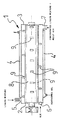
- an apparatus used for the method of concentration according to the invention comprises a turbo-concentrator formed basically by a cylindrical tubular body 1 which is closed at the opposite ends by bases 2, 3 and which is provided coaxially with a heating jacket 4 through which a fluid, for example diathermic oil, is to flow in order to maintain the internal wall of the body 1 at a predetermined temperature.
- a fluid for example diathermic oil
- the tubular body 1 is provided with an opening 5 for the entry of the liquid mixture to be concentrated, an opening 6 for the stream of hot dry air, and also an opening 7 for the discharge of the concentrated liquid mixture.
- a bladed rotor 8 the blades 9 of which are arranged helically and are orientated to centrifuge and simultaneously convey to the outlet the liquid mixture to be concentrated, is rotatably supported in the tubular body 1.
- a motor M is provided to operate the bladed rotor at variable speeds.
- a 35% solution of acetylated starch in acetic acid having a degree of acetylation equal to saturation was fed continuously into the turbo-concentrator described above at a flow rate of 100 kg/h.
- the internal wall of the turbo-concentrator was maintained at a temperature of 130°C.
- the solution so obtained had a concentration of 80%.
- the temperature of the internal wall of the turbo-concentrator was 120°C
- the circumferential speed of the bladed rotor was 40 m/s
- the residence time in the turbo-concentrator was 1 minute.
- the stream leaving the turbo-concentrator, having a 90% solids content was then discharged in the form of a molten mass and conveyed to a suitable storage unit.
- a 75% solution of sorbitol in water was fed into the turbo-concentrator at a flow rate of 100 kg/h.
- the temperature of the internal wall of the turbo-concentrator 1 was 140°C
- the circumferential speed of the bladed rotor was 40 m/s
- the residence time in the turbo-concentrator 1 was 2 minutes.
- the concentrated stream leaving the turbo-concentrator exhibited a 99% solids content.
- a saline solution of dump effluent as such or coming from a membrane concentration plant with an average solids content of 2% was fed into the turbo-concentrator at a flow rate of 1000 kg/h.
- the temperature of the internal wall of the turbo-concentrator 1 was 240°C
- the circumferential speed of the bladed rotor was 40 m/s
- the residence time in the turbo-concentrator 1 was 2 minutes.
- the concentrated stream leaving the turbo-concentrator exhibited a 50% solids content.
Landscapes
- Chemical & Material Sciences (AREA)
- Chemical Kinetics & Catalysis (AREA)
- Vaporization, Distillation, Condensation, Sublimation, And Cold Traps (AREA)
- Centrifugal Separators (AREA)
- Crystals, And After-Treatments Of Crystals (AREA)
- Supply And Distribution Of Alternating Current (AREA)
Abstract
Description
- feeding a continuous stream of liquid mixture into the turbo-concentrator in which the bladed rotor is rotated at circumferential speeds variable from 30 to 50 m/s,
- centrifuging the liquid mixture to form a dynamic and tubular thin layer in which the liquid mixture is maintained in a state of high turbulence by the blades of the bladed rotor,
- advancing the dynamic and tubular thin layer to the discharge opening of the turbo-concentrator, causing it to flow substantially in contact with the heated wall of the latter to the discharge opening,
- discharging continuously a stream of concentrated liquid mixture.
Claims (4)
- Method for the concentration of liquid mixtures, comprising the step of causing a continuous stream of the liquid mixtures to flow in the form of a turbulent thin layer in contact with a heated wall.
- Method for the concentration of liquid mixtures, characterised in that it comprises the steps of:feeding a continuous stream of liquid mixture into a turbo-concentrator comprising a cylindrical tubular body (1) which has a horizontal axis and which is equipped with an opening (5) for the introduction of the liquid mixture and with an opening (7) for the discharge of the final product, a heating jacket (4) for heating the internal wall of the tubular body to a predetermined temperature, and a bladed rotor (8) rotatably supported in the cylindrical tubular body (1) where it is rotated at circumferential speeds variable from 30 to 50 m/s,centrifuging the liquid mixture to form a dynamic and tubular thin layer in which the liquid mixture is maintained in a state of high turbulence by the blades (9) of the bladed rotor (8),advancing the dynamic tubular thin layer to the discharge opening (7) of the turbo-concentrator, causing it to flow substantially in contact with the heated wall of the latter to the discharge opening,discharging continuously a stream of concentrated liquid mixture.
- Method according to Claim 2, characterised in that a stream of hot dry air is fed into the turbo-concentrator in the same direction as the continuous stream of liquid mixture.
- Method according to Claim 2 or 3, characterised in that a portion of the continuous stream of concentrated liquid mixture leaving the turbo-concentrator is fed in again continuously upstream of the turbo-concentrator.
Applications Claiming Priority (3)
| Application Number | Priority Date | Filing Date | Title |
|---|---|---|---|
| IT96MI002091A IT1285493B1 (en) | 1996-10-10 | 1996-10-10 | METHOD FOR THE CONCENTRATION OF LIQUID MIXTURES |
| ITMI962091 | 1996-10-10 | ||
| US08/948,157 US6146493A (en) | 1996-10-10 | 1997-10-09 | Method for the concentration of liquid mixtures |
Publications (2)
| Publication Number | Publication Date |
|---|---|
| EP0835679A1 true EP0835679A1 (en) | 1998-04-15 |
| EP0835679B1 EP0835679B1 (en) | 2005-07-27 |
Family
ID=26331433
Family Applications (1)
| Application Number | Title | Priority Date | Filing Date |
|---|---|---|---|
| EP97203081A Expired - Lifetime EP0835679B1 (en) | 1996-10-10 | 1997-10-06 | Method for the concentration of liquid mixtures |
Country Status (8)
| Country | Link |
|---|---|
| US (2) | US6146493A (en) |
| EP (1) | EP0835679B1 (en) |
| AT (1) | ATE300344T1 (en) |
| BR (2) | BR9705396A (en) |
| CA (1) | CA2217906C (en) |
| DE (1) | DE69733795T2 (en) |
| ES (1) | ES2247614T3 (en) |
| IT (1) | IT1285493B1 (en) |
Cited By (3)
| Publication number | Priority date | Publication date | Assignee | Title |
|---|---|---|---|---|
| EP1071673A1 (en) | 1998-04-17 | 2001-01-31 | Dsm N.V. | Process for drying melamine |
| EP1906123A3 (en) * | 2006-09-27 | 2009-03-25 | Geoline S.r.l. | System for securing plants for drying organic substances susceptible of causing explosive reactions and process for drying said substances |
| IT201900023046A1 (en) * | 2019-12-05 | 2021-06-05 | Vomm Impianti E Processi S P A | Product in the form of a powder comprising lactose and its production process |
Families Citing this family (6)
| Publication number | Priority date | Publication date | Assignee | Title |
|---|---|---|---|---|
| US6027919A (en) | 1993-12-07 | 2000-02-22 | Genetics Institute, Inc. | BMP-12 and BMP-13 proteins and DNA encoding them |
| US20090324907A1 (en) * | 1999-07-08 | 2009-12-31 | D Amato Salvatore F | Tamper evident and resisting informational article and method of producing same |
| US20040253312A1 (en) * | 2001-09-28 | 2004-12-16 | Sowden Harry S. | Immediate release dosage form comprising shell having openings therein |
| RU2223130C1 (en) * | 2002-07-12 | 2004-02-10 | ООО "Марс" | Method of evaporation and vortex film-type evaporator for realization of this method |
| KR100802340B1 (en) | 2006-05-11 | 2008-02-13 | 김태욱 | Evaporator |
| IT202000012517A1 (en) * | 2020-05-27 | 2021-11-27 | Vomm Impianti E Processi S P A | PROCEDURE FOR THE CONTINUOUS SANITIZATION OF WASTEWATER |
Citations (4)
| Publication number | Priority date | Publication date | Assignee | Title |
|---|---|---|---|---|
| US4683026A (en) * | 1984-05-22 | 1987-07-28 | Vaclav Feres | Thin layer evaporator |
| US5256250A (en) * | 1991-07-23 | 1993-10-26 | Rudolf Pelzer | Thin film evaporator |
| US5409643A (en) * | 1991-11-13 | 1995-04-25 | Vomm Impianti E Processi S.R.L. | Method of making a granular product with a high specific weight |
| EP0711505A1 (en) * | 1994-10-21 | 1996-05-15 | VOMM IMPIANTI E PROCESSI S.r.L. | Method of continuous chocolate conching |
Family Cites Families (7)
| Publication number | Priority date | Publication date | Assignee | Title |
|---|---|---|---|---|
| US3357477A (en) * | 1966-12-23 | 1967-12-12 | Artisan Ind | Thin film processing apparatus |
| US3751010A (en) * | 1971-08-16 | 1973-08-07 | Monsanto Co | Mixer |
| US3985606A (en) * | 1974-08-02 | 1976-10-12 | Artisan Industries Inc. | Low-pressure deentrainment evaporator |
| US4894117A (en) * | 1988-04-28 | 1990-01-16 | Colgate-Palmolive Company | Process for manufacturing high bulk density particulate fabric softening synthetic anionic organic detergent compositions |
| US5028297A (en) * | 1989-01-27 | 1991-07-02 | Vestar, Inc. | Film-forming evaporation apparatus |
| EP0710670B1 (en) * | 1994-11-03 | 2000-06-14 | VOMM IMPIANTI E PROCESSI S.r.L. | A method of modifying starch |
| AU5443096A (en) * | 1995-06-05 | 1996-12-24 | Kraft Foods, Inc. | Method for reducing the viscosity of chocolate |
-
1996
- 1996-10-10 IT IT96MI002091A patent/IT1285493B1/en active IP Right Grant
-
1997
- 1997-10-06 DE DE69733795T patent/DE69733795T2/en not_active Expired - Lifetime
- 1997-10-06 EP EP97203081A patent/EP0835679B1/en not_active Expired - Lifetime
- 1997-10-06 ES ES97203081T patent/ES2247614T3/en not_active Expired - Lifetime
- 1997-10-06 AT AT97203081T patent/ATE300344T1/en not_active IP Right Cessation
- 1997-10-09 CA CA002217906A patent/CA2217906C/en not_active Expired - Lifetime
- 1997-10-09 US US08/948,157 patent/US6146493A/en not_active Expired - Lifetime
- 1997-10-10 BR BR9705396-1A patent/BR9705396A/en not_active IP Right Cessation
- 1997-10-10 BR BR9706396-7A patent/BR9706396A/en unknown
-
2000
- 2000-10-17 US US09/688,743 patent/US6837969B1/en not_active Expired - Lifetime
Patent Citations (4)
| Publication number | Priority date | Publication date | Assignee | Title |
|---|---|---|---|---|
| US4683026A (en) * | 1984-05-22 | 1987-07-28 | Vaclav Feres | Thin layer evaporator |
| US5256250A (en) * | 1991-07-23 | 1993-10-26 | Rudolf Pelzer | Thin film evaporator |
| US5409643A (en) * | 1991-11-13 | 1995-04-25 | Vomm Impianti E Processi S.R.L. | Method of making a granular product with a high specific weight |
| EP0711505A1 (en) * | 1994-10-21 | 1996-05-15 | VOMM IMPIANTI E PROCESSI S.r.L. | Method of continuous chocolate conching |
Cited By (6)
| Publication number | Priority date | Publication date | Assignee | Title |
|---|---|---|---|---|
| EP1071673A1 (en) | 1998-04-17 | 2001-01-31 | Dsm N.V. | Process for drying melamine |
| EP1906123A3 (en) * | 2006-09-27 | 2009-03-25 | Geoline S.r.l. | System for securing plants for drying organic substances susceptible of causing explosive reactions and process for drying said substances |
| US7877896B2 (en) | 2006-09-27 | 2011-02-01 | Geoline S.R.L. | System for making plants for drying solid organic substances in aqueous phase capable of causing explosive reactions safe and process for drying said substances |
| IT201900023046A1 (en) * | 2019-12-05 | 2021-06-05 | Vomm Impianti E Processi S P A | Product in the form of a powder comprising lactose and its production process |
| WO2021110832A1 (en) * | 2019-12-05 | 2021-06-10 | Vomm Impianti E Processi S.P.A. | Lactose-containing product in powder form and production process thereof |
| US12478072B2 (en) | 2019-12-05 | 2025-11-25 | Vomm Impianti E Processi S.P.A. | Lactose-containing product in powder form and production process thereof |
Also Published As
| Publication number | Publication date |
|---|---|
| ATE300344T1 (en) | 2005-08-15 |
| IT1285493B1 (en) | 1998-06-08 |
| DE69733795T2 (en) | 2006-05-24 |
| DE69733795D1 (en) | 2005-09-01 |
| ITMI962091A1 (en) | 1998-04-10 |
| US6146493A (en) | 2000-11-14 |
| EP0835679B1 (en) | 2005-07-27 |
| US6837969B1 (en) | 2005-01-04 |
| BR9706396A (en) | 2000-05-09 |
| CA2217906A1 (en) | 1998-04-10 |
| CA2217906C (en) | 2006-12-05 |
| ES2247614T3 (en) | 2006-03-01 |
| BR9705396A (en) | 2002-01-08 |
Similar Documents
| Publication | Publication Date | Title |
|---|---|---|
| JP3674868B2 (en) | Equipment for processing process materials such as waste materials | |
| CN101805445B (en) | Chemical treating method for melt polycondensation high polymer old material regeneration | |
| US6146493A (en) | Method for the concentration of liquid mixtures | |
| JPH04227865A (en) | Centrifogal separation type drier | |
| JPH10510583A (en) | Thin film processing equipment | |
| EP0710670A1 (en) | A method of modifying starch | |
| US5164030A (en) | Continuous process for the separation of solutions and suspensions | |
| US4321106A (en) | Method of and apparatus for the thermal treatment of flowable material | |
| JPH09508595A (en) | Method and apparatus for utilizing cable residue and cable debris coated or surrounded by synthetic resin to recover metal and fractionated renewable synthetic resin separately | |
| CN219079196U (en) | Sewage treatment pond for chemical production | |
| CN114929377A (en) | Apparatus and method for depolymerization of polymers | |
| KR100754978B1 (en) | Rotary Round Coil Thickeners | |
| CN210874150U (en) | Scraper film evaporator | |
| CN211752556U (en) | Scale-proof centrifugal scraper film evaporator | |
| CN215326952U (en) | Impurity removing device for producing potassium dihydrogen phosphate by wet-process phosphoric acid extraction | |
| US2581081A (en) | Glue drying process | |
| CN115404104B (en) | Acetylene generator convenient to arrange sediment | |
| CN104892621B (en) | Energy-saving emission-reduction process for producing pyromellitic dianhydride in solvent refining method | |
| CN1233521A (en) | Method and apparatus for recovering crystals from slurry | |
| CN214141666U (en) | Be applied to terminal curing equipment of waste water zero release | |
| CN211226970U (en) | Multifunctional device for producing gamma-aminobutyric acid | |
| JPH11319899A (en) | Sludge treatment system | |
| CN115536190A (en) | Industrial high-salinity wastewater recycling system and process | |
| CN219984163U (en) | Acid mother liquor crude drug recovery device in glyphosate production process | |
| US1475314A (en) | Method of and apparatus for evaporating liquids |
Legal Events
| Date | Code | Title | Description |
|---|---|---|---|
| PUAI | Public reference made under article 153(3) epc to a published international application that has entered the european phase |
Free format text: ORIGINAL CODE: 0009012 |
|
| AK | Designated contracting states |
Kind code of ref document: A1 Designated state(s): AT BE CH DE DK ES FR GB GR IE IT LI LU MC NL PT SE |
|
| AX | Request for extension of the european patent |
Free format text: AL;LT;LV;RO;SI |
|
| 17P | Request for examination filed |
Effective date: 19981009 |
|
| AKX | Designation fees paid |
Free format text: AT BE CH DE DK ES FR GB GR IE IT LI LU MC NL PT SE |
|
| RBV | Designated contracting states (corrected) |
Designated state(s): AT BE CH DE DK ES FR GB GR IE IT LI LU MC NL PT SE |
|
| 17Q | First examination report despatched |
Effective date: 20020606 |
|
| GRAP | Despatch of communication of intention to grant a patent |
Free format text: ORIGINAL CODE: EPIDOSNIGR1 |
|
| GRAS | Grant fee paid |
Free format text: ORIGINAL CODE: EPIDOSNIGR3 |
|
| GRAA | (expected) grant |
Free format text: ORIGINAL CODE: 0009210 |
|
| AK | Designated contracting states |
Kind code of ref document: B1 Designated state(s): AT BE CH DE DK ES FR GB GR IE IT LI LU MC NL PT SE |
|
| PG25 | Lapsed in a contracting state [announced via postgrant information from national office to epo] |
Ref country code: LI Free format text: LAPSE BECAUSE OF FAILURE TO SUBMIT A TRANSLATION OF THE DESCRIPTION OR TO PAY THE FEE WITHIN THE PRESCRIBED TIME-LIMIT Effective date: 20050727 Ref country code: CH Free format text: LAPSE BECAUSE OF FAILURE TO SUBMIT A TRANSLATION OF THE DESCRIPTION OR TO PAY THE FEE WITHIN THE PRESCRIBED TIME-LIMIT Effective date: 20050727 Ref country code: BE Free format text: LAPSE BECAUSE OF FAILURE TO SUBMIT A TRANSLATION OF THE DESCRIPTION OR TO PAY THE FEE WITHIN THE PRESCRIBED TIME-LIMIT Effective date: 20050727 Ref country code: AT Free format text: LAPSE BECAUSE OF FAILURE TO SUBMIT A TRANSLATION OF THE DESCRIPTION OR TO PAY THE FEE WITHIN THE PRESCRIBED TIME-LIMIT Effective date: 20050727 |
|
| REG | Reference to a national code |
Ref country code: GB Ref legal event code: FG4D |
|
| REG | Reference to a national code |
Ref country code: CH Ref legal event code: EP |
|
| REG | Reference to a national code |
Ref country code: IE Ref legal event code: FG4D |
|
| REF | Corresponds to: |
Ref document number: 69733795 Country of ref document: DE Date of ref document: 20050901 Kind code of ref document: P |
|
| PG25 | Lapsed in a contracting state [announced via postgrant information from national office to epo] |
Ref country code: IE Free format text: LAPSE BECAUSE OF NON-PAYMENT OF DUE FEES Effective date: 20051006 |
|
| PG25 | Lapsed in a contracting state [announced via postgrant information from national office to epo] |
Ref country code: SE Free format text: LAPSE BECAUSE OF FAILURE TO SUBMIT A TRANSLATION OF THE DESCRIPTION OR TO PAY THE FEE WITHIN THE PRESCRIBED TIME-LIMIT Effective date: 20051027 Ref country code: GR Free format text: LAPSE BECAUSE OF FAILURE TO SUBMIT A TRANSLATION OF THE DESCRIPTION OR TO PAY THE FEE WITHIN THE PRESCRIBED TIME-LIMIT Effective date: 20051027 Ref country code: GB Free format text: LAPSE BECAUSE OF NON-PAYMENT OF DUE FEES Effective date: 20051027 Ref country code: DK Free format text: LAPSE BECAUSE OF FAILURE TO SUBMIT A TRANSLATION OF THE DESCRIPTION OR TO PAY THE FEE WITHIN THE PRESCRIBED TIME-LIMIT Effective date: 20051027 |
|
| PG25 | Lapsed in a contracting state [announced via postgrant information from national office to epo] |
Ref country code: MC Free format text: LAPSE BECAUSE OF NON-PAYMENT OF DUE FEES Effective date: 20051031 Ref country code: LU Free format text: LAPSE BECAUSE OF NON-PAYMENT OF DUE FEES Effective date: 20051031 |
|
| PG25 | Lapsed in a contracting state [announced via postgrant information from national office to epo] |
Ref country code: PT Free format text: LAPSE BECAUSE OF FAILURE TO SUBMIT A TRANSLATION OF THE DESCRIPTION OR TO PAY THE FEE WITHIN THE PRESCRIBED TIME-LIMIT Effective date: 20051227 |
|
| REG | Reference to a national code |
Ref country code: CH Ref legal event code: PL |
|
| REG | Reference to a national code |
Ref country code: ES Ref legal event code: FG2A Ref document number: 2247614 Country of ref document: ES Kind code of ref document: T3 |
|
| ET | Fr: translation filed | ||
| PLBE | No opposition filed within time limit |
Free format text: ORIGINAL CODE: 0009261 |
|
| STAA | Information on the status of an ep patent application or granted ep patent |
Free format text: STATUS: NO OPPOSITION FILED WITHIN TIME LIMIT |
|
| GBPC | Gb: european patent ceased through non-payment of renewal fee |
Effective date: 20051027 |
|
| 26N | No opposition filed |
Effective date: 20060428 |
|
| REG | Reference to a national code |
Ref country code: IE Ref legal event code: MM4A |
|
| REG | Reference to a national code |
Ref country code: FR Ref legal event code: PLFP Year of fee payment: 20 |
|
| PGFP | Annual fee paid to national office [announced via postgrant information from national office to epo] |
Ref country code: NL Payment date: 20160923 Year of fee payment: 20 |
|
| PGFP | Annual fee paid to national office [announced via postgrant information from national office to epo] |
Ref country code: FR Payment date: 20160921 Year of fee payment: 20 |
|
| PGFP | Annual fee paid to national office [announced via postgrant information from national office to epo] |
Ref country code: ES Payment date: 20160922 Year of fee payment: 20 |
|
| PGFP | Annual fee paid to national office [announced via postgrant information from national office to epo] |
Ref country code: DE Payment date: 20160922 Year of fee payment: 20 |
|
| PGFP | Annual fee paid to national office [announced via postgrant information from national office to epo] |
Ref country code: IT Payment date: 20160923 Year of fee payment: 20 |
|
| REG | Reference to a national code |
Ref country code: DE Ref legal event code: R071 Ref document number: 69733795 Country of ref document: DE |
|
| REG | Reference to a national code |
Ref country code: NL Ref legal event code: MK Effective date: 20171005 |
|
| REG | Reference to a national code |
Ref country code: ES Ref legal event code: FD2A Effective date: 20180508 |
|
| PG25 | Lapsed in a contracting state [announced via postgrant information from national office to epo] |
Ref country code: ES Free format text: LAPSE BECAUSE OF EXPIRATION OF PROTECTION Effective date: 20171007 |