EP0835514B1 - Bobbin-mounted soleonoid coil - Google Patents
Bobbin-mounted soleonoid coil Download PDFInfo
- Publication number
- EP0835514B1 EP0835514B1 EP96920656A EP96920656A EP0835514B1 EP 0835514 B1 EP0835514 B1 EP 0835514B1 EP 96920656 A EP96920656 A EP 96920656A EP 96920656 A EP96920656 A EP 96920656A EP 0835514 B1 EP0835514 B1 EP 0835514B1
- Authority
- EP
- European Patent Office
- Prior art keywords
- socket
- bobbin
- magnet wire
- flange
- coil
- Prior art date
- Legal status (The legal status is an assumption and is not a legal conclusion. Google has not performed a legal analysis and makes no representation as to the accuracy of the status listed.)
- Expired - Lifetime
Links
- 238000004519 manufacturing process Methods 0.000 description 15
- 238000000034 method Methods 0.000 description 8
- 230000005291 magnetic effect Effects 0.000 description 7
- 238000003780 insertion Methods 0.000 description 6
- 230000037431 insertion Effects 0.000 description 6
- 238000004804 winding Methods 0.000 description 6
- 230000004907 flux Effects 0.000 description 5
- 238000010276 construction Methods 0.000 description 3
- 230000005294 ferromagnetic effect Effects 0.000 description 3
- 230000000712 assembly Effects 0.000 description 2
- 238000000429 assembly Methods 0.000 description 2
- 238000011217 control strategy Methods 0.000 description 2
- 238000010008 shearing Methods 0.000 description 2
- 235000001674 Agaricus brunnescens Nutrition 0.000 description 1
- 239000004215 Carbon black (E152) Substances 0.000 description 1
- 230000004323 axial length Effects 0.000 description 1
- 230000033228 biological regulation Effects 0.000 description 1
- 230000015572 biosynthetic process Effects 0.000 description 1
- 238000005520 cutting process Methods 0.000 description 1
- 238000005755 formation reaction Methods 0.000 description 1
- 229930195733 hydrocarbon Natural products 0.000 description 1
- 150000002430 hydrocarbons Chemical class 0.000 description 1
- 238000001746 injection moulding Methods 0.000 description 1
- 238000009413 insulation Methods 0.000 description 1
- 230000014759 maintenance of location Effects 0.000 description 1
- 239000000463 material Substances 0.000 description 1
- 230000013011 mating Effects 0.000 description 1
- 239000002991 molded plastic Substances 0.000 description 1
- 239000004033 plastic Substances 0.000 description 1
- 238000010926 purge Methods 0.000 description 1
Images
Classifications
-
- H—ELECTRICITY
- H01—ELECTRIC ELEMENTS
- H01F—MAGNETS; INDUCTANCES; TRANSFORMERS; SELECTION OF MATERIALS FOR THEIR MAGNETIC PROPERTIES
- H01F5/00—Coils
- H01F5/04—Arrangements of electric connections to coils, e.g. leads
-
- H—ELECTRICITY
- H01—ELECTRIC ELEMENTS
- H01F—MAGNETS; INDUCTANCES; TRANSFORMERS; SELECTION OF MATERIALS FOR THEIR MAGNETIC PROPERTIES
- H01F41/00—Apparatus or processes specially adapted for manufacturing or assembling magnets, inductances or transformers; Apparatus or processes specially adapted for manufacturing materials characterised by their magnetic properties
- H01F41/02—Apparatus or processes specially adapted for manufacturing or assembling magnets, inductances or transformers; Apparatus or processes specially adapted for manufacturing materials characterised by their magnetic properties for manufacturing cores, coils, or magnets
- H01F41/04—Apparatus or processes specially adapted for manufacturing or assembling magnets, inductances or transformers; Apparatus or processes specially adapted for manufacturing materials characterised by their magnetic properties for manufacturing cores, coils, or magnets for manufacturing coils
- H01F41/10—Connecting leads to windings
-
- H—ELECTRICITY
- H01—ELECTRIC ELEMENTS
- H01F—MAGNETS; INDUCTANCES; TRANSFORMERS; SELECTION OF MATERIALS FOR THEIR MAGNETIC PROPERTIES
- H01F5/00—Coils
- H01F5/02—Coils wound on non-magnetic supports, e.g. formers
-
- H—ELECTRICITY
- H01—ELECTRIC ELEMENTS
- H01F—MAGNETS; INDUCTANCES; TRANSFORMERS; SELECTION OF MATERIALS FOR THEIR MAGNETIC PROPERTIES
- H01F7/00—Magnets
- H01F7/06—Electromagnets; Actuators including electromagnets
- H01F2007/062—Details of terminals or connectors for electromagnets
Definitions
- This invention relates generally to bobbin-mounted solenoid coils and methods of making them.
- solenoid coil assembly It is a common practice to make a solenoid coil assembly by winding a length of magnet wire on a non-magnetic bobbin to form an electromagnet coil and establishing electrical connection of end portions of the wire with respective electrical terminals that are mounted on the bobbin. Application of voltage across the terminals creates current flow in the coil that results in the creation of magnetic flux symbolized by endless lines of flux that envelope the coil in a generally toroidal pattern.
- Such solenoid coil assemblies are commonly used in electromagnetic-actuated valves to control the opening and closing of the valves.
- Such valves typically include ferromagnetic stator structure that envelopes the bobbin-mounted coil to provide a magnetic circuit path for concentrating the magnetic flux.
- a small air gap is present in the stator structure within a central through-hole that extends axially through the bobbin's core, or at least immediately proximate such through-hole.
- a ferromagnetic armature is disposed proximate the air gap so that the magnetic circuit flux passes through a portion of the armature as it passes across the air gap.
- an axial component of magnetic force is exerted on the armature in one axial direction for operating the valve, typically against a counter force provided by a spring that acts to urge the armature in the opposite axial direction. If the spring normally biases the valve closed when there is no current flow in the coil, increasing current flow in the coil will typically increase the amount of valve opening.
- valves that utilize such bobbin-mounted solenoid coils.
- Two examples, among others, are canister purge solenoid valves and exhaust gas recirculation valves. Because of increasingly stricter regulations pertaining to vehicle tailpipe and hydrocarbon emissions, it is becoming increasingly important that such valves be capable of exercising more precise control. While various control strategies may accomplish more precise control, they may be limited by the construction of the particular solenoid-actuated valve that is involved. An improved construction of a solenoid coil assembly of such a valve is one means for allowing more accurate control strategies to be successfully implemented.
- the present invention relates to an improved construction for such a solenoid coil assembly. More specifically, the invention provides a solenoid coil assembly in which are tensioned, not only the convolutions of the magnet wire wound around the core of the bobbin, but also the end segments of the magnet wire extending from the convoluted coil to respective bobbin-mounted electrical terminals to which the respective end segments of the magnet wire are electrically joined.
- the tensioning technique of the present invention in conjunction with "precision winding" of the magnet wire to form the coil, the magnetic flux vs. electric current characteristic of a bobbin-mounted electromagnet coil can be accurately established.
- Mass-production manufacture and assembly of automotive vehicle components parts must be cost-effective in order to be commercially viable. This usually requires that such parts be suited for automated fabrication and assembly methods.
- the present invention relates to a method of making a bobbin-mounted solenoid coil that is well-suited for cost-effective automated fabrication using essentially conventional manufacturing equipment and techniques. This capability is due in large part to certain constructional features of the bobbin.
- the invention in a presently preferred embodiment, comprises a bobbin that is fabricated by convention injection molding techniques to provide means for tensioning end segments of the magnet wire and establishing electrical connection of the respective tensioned end segments with respective electrical terminals in such a way that in the finished bobbin-mounted solenoid coil, the tension is maintained not only in the convolutions of the coil, but also in those portions of the end segments that extend from the terminals to the coil.
- the tensioning and winding of the magnet wire on the bobbin in accordance with the inventive principles can be performed by conventional equipment adapted to achieve the cost-effective automated fabrication of the inventive bobbin-mounted coil assemblies. Assembly of the electrical terminals to the end segments of the bobbin-mounted coil can be performed entirely mechanically by simple insertion operations.
- a bobbin-mounted solenoid coil including a bobbin onto which a length of insulated magnet wire having end segments is wound to create said a bobbin-mounted solenoid coil
- the bobbin comprising:- a central tubular cylindrical core disposed concentric with an imaginary longitudinal axis and having a radial flange directed outwardly from the core, said flange having opposite axial faces one of which faces toward that portion of said core around which convolutions of magnet wire are to be wound and the other of which is opposite said one face; electric terminal mounting means on said other face providing for at least one electric terminal to be mounted thereon, said electric terminal mounting means comprising at least one socket having a generally rectangular wall open at its top end for accepting an electrical terminal therein for making electrical contact with said end segments; and guide means for guiding passage of said magnet wire across said electric terminal mounting means and said other face of said flange to said one face; characterised in that said at least one socket has a slot, a ramped track and a
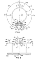
- Figs. 1-8 show a bobbin 22 that is used in making a solenoid coil assembly.
- the bobbin is preferably an injection-molded plastic that possesses dimensional stability over a range of temperature extremes that are typically encountered in automotive engine usage.
- Bobbin 22 comprises a straight cylindrical tubular core 24 coaxial with a main longitudinal axis 26, and upper and lower flanges 28 and 30 at the opposite axial ends of core 24. As will be explained in conjunction with later drawing Figs., a length of magnet wire is wound on core 24 between flanges 28, 30 to form an electromagnet coil on bobbin 22.
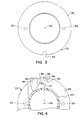
- Lower flange 30 has a circular shape whose outer perimeter is interrupted at one location by a small inwardly extending slot 34.
- Upper flange 28 also has a circular shape, but its outer perimeter is interrupted by two closely adjacent slots 36 and 38 that have somewhat different shapes.
- Slot 36 is basically U-shaped.
- One side of slot 38 is slightly more than a half-U-shape while the other side 39 runs along a straight line extending from a point of tangency 40 with the first side at about 55 degrees to a radial 41 to where it meets the circular outer perimeter of the flange.
- the lower face of flange 28 comprises shallow recess 42 that is seen in Fig. 4 to be somewhat triangularly shaped.
- Shallow recess 42 comprises an edge surface 44 that extends from a point of tangency 46 with the O.D. of core 24 to a location on the perimeter of flange 28 that is between slots 38 and 36. Edge surface 44 makes an angle 50 with radial 41 that is approximately 35 degrees.
- the upper face of flange 28 contains two upstanding cylindrical posts 52 and 54 that are diametrically opposite each other and equidistant from axis 26 and whose upper ends are tapered.
- a further upright post 56 having a generally rectangular shape with a radially outwardly projecting overhang 58 at its top that is also slightly wider in the circumferential sense about axis 26 than is that portion of the post below the overhang.
- a pair of upright, side-by-side, walled sockets 60 and 62 are adapted for receiving a respective electrical terminal like the one depicted in Figs. 9-12 (to be described in detail later) and to provide for the electrical connection of a respective terminal with a respective end segment of a magnet wire wound on bobbin 22.
- Each socket has a generally rectangular wall that is open at the top for insertion of an electric terminal.
- Each socket is disposed to an opposite circumferential side of an imaginary diameter that extends across the bobbin from post 56.
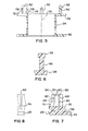
- the opposed radially inner and radially outer portions of each socket wall contain straight narrow slots 66 and 68 respectively that are in parallel and mutual alignment across the respective socket.
- the slots are open at the top where they have a lead that facilitates the passage of respective segments of the coil magnet wire into the slots, as will be explained in greater detail later on.
- a respective grooved track 70 and 72 ramps upwardly from a respective slot 36, 38 to the bottom of the radially outer slot 68 of a respective socket 60, 62.
- a respective short grooved track 74 and 76 is provided on the radially inner wall of the respective socket 60, 62 slightly above the upper face of flange 28, each track 74, 76 having a groove that extends from the bottom of the radially inner slot 66 of the respective socket 60, 62 toward the open center of the bobbin as viewed in plan. Integral formations 78 serve to rigidify the sockets to flange 28.
- the upper rectangular rim of each socket has a chamfer 80 to facilitate terminal insertion, and each socket has shallow axial grooves 82 proximate its four corners.
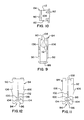
- Figs. 9-12 illustrate an electric terminal 84 prior to its insertion into a respective one of the sockets 60, 62.
- a like electric terminal 86 (Figs. 17 and 18) is inserted into the other socket.
- Terminal 84 is fabricated as a single piece from flat strip stock to comprise a generally U-shaped body having a base 88 whose opposite ends join with flat sides 90 and 92 respectively along 90 degree radii, as shown by Fig. 9.
- Each side contains a centrally located axial slot 94 that is open at base 88 and extends upwardly therefrom for about one-half the overall axial length of the side.
- a slot 94 comprises an entrance lead 96 that extends to a straight section 98 which in turn extends via a tapered section 100 to a narrower straight section 102.
- the material is slit, as shown at 104 in Figs. 11 and 12, adjacent each side of section 98.
- the outer edges of sides 90, 92 contain pointed retention barbs 106.
- a somewhat T-shaped tab 108 inclines downwardly and inwardly from the central portion of the top edge of side 92, stopping short of the opposite side 90 to provide an insertion space 110 for a mating terminal (not shown).
- the wings 112 of the T-shape are curled back toward, but stop short of, side 92.
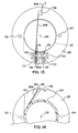
- magnet wire MW is tightly wrapped around post 56 below overhang 58. It is then brought across the bobbin to run in and along the groove of track 74, thence pass through slot 66 of socket 60 and across the socket's interior to exit the socket by passing through slot 68. From slot 68 the magnet wire runs in and along the groove of ramped track 70 to enter slot 36 where it loops around the edge of the slot to the bottom face of flange 28.
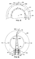
- Fig. 14 shows the magnet wire extending within recess 42 from the edge of slot 36 to tangency with core 24 where it begins to form convolutions around the core between flanges 28, 30 to ultimately create an electromagnet coil 114, as shown in Fig. 15.
- the latter Fig. further shows the magnet wire extending from the final convolution of the coil to slot 38 where the magnet wire loops around the edge of the slot to the upper face of flange 28.
- Fig. 16 shows the magnet wire extending from slot 38 to run in and along the groove in ramped track 72 and thence enter socket 62 by passing through slot 68 of that socket.
- the magnet wire passes across the interior of the socket, exiting via slot 66 to run in and along the groove in track 76.
- the magnet wire Upon leaving track 76, the magnet wire extends across the bobbin to an end segment of the magnet wire that is wrapped, or tied, securely around post 56.
- Terminals 84, 86 are then assembled by aligning each with the open end of a respective socket 60, 62 and forcefully inserting them into the sockets.
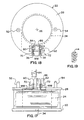
- Fig. 17 shows terminal 86 inserted into socket 62 and terminal 84 poised for insertion into socket 60, it is more efficient to simultaneously insert both terminals into their sockets.
- the portion of the magnet wire spanning the interior of the socket enters slots 94.
- Leads 96 facilitate entry into the narrow portions of the slots.
- the magnet wire is lodged in section 102 in electric contact with the terminal.
- Each slot is dimensioned in relation to the diameter of the magnet wire to scrape away the thin insulation covering the magnet wire so that the electric contact is thereby established.
- Barbs 106 embed slightly into the wall of the socket to securely retain the terminal in the socket.
- the tensioned magnet wire running across the interior of each socket is also wedged in the terminal slots so that the magnet wire is maintained in tension.
- the two posts 52, 54 provide for mounting of the bobbin-mounted coil directly on an associated stator structure (not shown).
- Such stator structure comprising a ferromagnetic pole piece having a radial flange containing a central axial opening that is concentric with axis 26 and two through-holes spaced radially outwardly therefrom.
- the upper face of flange 28 is disposed flat against the lower face of the pole piece flange with posts 52, 54 extending through the respective through-holes in the pole piece flange.
- the tapered ends of the posts are then deformed by any suitable plastic deformation process to create mushroom heads that bear against the upper face of the pole piece flange.
Landscapes
- Engineering & Computer Science (AREA)
- Power Engineering (AREA)
- Manufacturing & Machinery (AREA)
- Electromagnets (AREA)
- Tension Adjustment In Filamentary Materials (AREA)
Abstract
Description
- This invention relates generally to bobbin-mounted solenoid coils and methods of making them.
- It is a common practice to make a solenoid coil assembly by winding a length of magnet wire on a non-magnetic bobbin to form an electromagnet coil and establishing electrical connection of end portions of the wire with respective electrical terminals that are mounted on the bobbin. Application of voltage across the terminals creates current flow in the coil that results in the creation of magnetic flux symbolized by endless lines of flux that envelope the coil in a generally toroidal pattern. Such solenoid coil assemblies are commonly used in electromagnetic-actuated valves to control the opening and closing of the valves.
- Such valves typically include ferromagnetic stator structure that envelopes the bobbin-mounted coil to provide a magnetic circuit path for concentrating the magnetic flux. A small air gap is present in the stator structure within a central through-hole that extends axially through the bobbin's core, or at least immediately proximate such through-hole. A ferromagnetic armature is disposed proximate the air gap so that the magnetic circuit flux passes through a portion of the armature as it passes across the air gap. As a result, an axial component of magnetic force is exerted on the armature in one axial direction for operating the valve, typically against a counter force provided by a spring that acts to urge the armature in the opposite axial direction. If the spring normally biases the valve closed when there is no current flow in the coil, increasing current flow in the coil will typically increase the amount of valve opening.
- A method of making solenoid coils suitable for such valves is described in US Patent No 4,251,911. The ends of the coil wire are wound around a first post prior to coil winding, and at the conclusion of coil winding, around a second post. The posts are integral with the bobbin. The bobbin is provided with terminal receiving cavities located such that the ends of the coil wire extends from the posts across the cavities. The electrical connections to the ends of the coil wire are made by cutting off the posts and thereby severing the wire at a location adjacent the posts and by inserting terminals into the cavities.
- In automotive vehicle applications there are a number of valves that utilize such bobbin-mounted solenoid coils. Two examples, among others, are canister purge solenoid valves and exhaust gas recirculation valves. Because of increasingly stricter regulations pertaining to vehicle tailpipe and hydrocarbon emissions, it is becoming increasingly important that such valves be capable of exercising more precise control. While various control strategies may accomplish more precise control, they may be limited by the construction of the particular solenoid-actuated valve that is involved. An improved construction of a solenoid coil assembly of such a valve is one means for allowing more accurate control strategies to be successfully implemented.
- In one respect, the present invention relates to an improved construction for such a solenoid coil assembly. More specifically, the invention provides a solenoid coil assembly in which are tensioned, not only the convolutions of the magnet wire wound around the core of the bobbin, but also the end segments of the magnet wire extending from the convoluted coil to respective bobbin-mounted electrical terminals to which the respective end segments of the magnet wire are electrically joined. By utilizing the tensioning technique of the present invention in conjunction with "precision winding" of the magnet wire to form the coil, the magnetic flux vs. electric current characteristic of a bobbin-mounted electromagnet coil can be accurately established.
- Mass-production manufacture and assembly of automotive vehicle components parts must be cost-effective in order to be commercially viable. This usually requires that such parts be suited for automated fabrication and assembly methods.
- In another respect, the present invention relates to a method of making a bobbin-mounted solenoid coil that is well-suited for cost-effective automated fabrication using essentially conventional manufacturing equipment and techniques. This capability is due in large part to certain constructional features of the bobbin.
- Briefly, the invention, in a presently preferred embodiment, comprises a bobbin that is fabricated by convention injection molding techniques to provide means for tensioning end segments of the magnet wire and establishing electrical connection of the respective tensioned end segments with respective electrical terminals in such a way that in the finished bobbin-mounted solenoid coil, the tension is maintained not only in the convolutions of the coil, but also in those portions of the end segments that extend from the terminals to the coil. The tensioning and winding of the magnet wire on the bobbin in accordance with the inventive principles can be performed by conventional equipment adapted to achieve the cost-effective automated fabrication of the inventive bobbin-mounted coil assemblies. Assembly of the electrical terminals to the end segments of the bobbin-mounted coil can be performed entirely mechanically by simple insertion operations.
- According to the present invention, there is provided a bobbin-mounted solenoid coil including a bobbin onto which a length of insulated magnet wire having end segments is wound to create said a bobbin-mounted solenoid coil, the bobbin comprising:- a central tubular cylindrical core disposed concentric with an imaginary longitudinal axis and having a radial flange directed outwardly from the core, said flange having opposite axial faces one of which faces toward that portion of said core around which convolutions of magnet wire are to be wound and the other of which is opposite said one face; electric terminal mounting means on said other face providing for at least one electric terminal to be mounted thereon, said electric terminal mounting means comprising at least one socket having a generally rectangular wall open at its top end for accepting an electrical terminal therein for making electrical contact with said end segments; and guide means for guiding passage of said magnet wire across said electric terminal mounting means and said other face of said flange to said one face; characterised in that said at least one socket has a slot, a ramped track and a track for locating an end segment of the magnet wire to span said at least one socket; and in that said guide means includes a single post which is disposed generally diametrically opposite said at least one socket and to which said end segments of said magnet wire are secured so that said end segment extends in tension across said at least one socket and continues in tension from said track to said post.
- Further features, advantages, and benefits of the invention will be seen in the ensuing description and claims that are accompanied by drawings. The drawings disclose a presently preferred embodiment of the invention according to the best mode contemplated at this time for carrying out the invention.
-
- Fig. 1 is a top plan view of a bobbin embodying principles of the invention.
- Fig. 2 is a front elevation view of Fig. 1.
- Fig. 3 is a bottom plan view of Fig. 2.
- Fig. 4 is a fragmentary cross sectional view as taken in the direction of arrows 4-4 in Fig. 2.
- Fig. 5 is a cross sectional view as taken in the direction of arrows 5-5 in Fig. 1.
- Fig. 6 is a fragmentary view, on an enlarged scale, as taken in the direction of arrows 6-6 in Fig. 1.
- Fig. 7 is an enlarged cross sectional view as taken in the direction of arrows 7-7 in Fig. 2.
- Fig. 8 is a full left side view of Fig. 7.
- Fig. 9 is a front elevation view of an electrical terminal shown by itself prior to association with the bobbin.
- Fig. 10 is a top plan view of Fig. 9.
- Fig. 11 is a right side elevation view of Fig. 9.
- Fig. 12 is a left side elevation view of Fig. 9.
- Fig. 13 is view similar to Fig. 1 illustrating a step in the method of making an electromagnet coil assembly using the bobbin of Fig. 1.
- Fig. 14 is view similar to Fig. 4 illustrating a further step in the method of making the electromagnet coil assembly.
- Fig. 15 is view similar to Fig. 4 illustrating a still further step in the method of making the electromagnet coil assembly.
- Fig. 16 is view similar to Fig. 1 illustrating a still further step in the method of making the electromagnet coil assembly.
- Fig. 17 is view similar to Fig. 2 illustrating a still further step in the method of making the electromagnet coil assembly.
- Fig. 18 is view similar to Fig. 1 illustrating a still further step in the method of making the electromagnet coil assembly.
- Fig. 19 is a fragmentary cross sectional view, on an enlarged scale, as taken in the direction of arrows 19-19 in Fig. 15.
-
- Figs. 1-8 show a
bobbin 22 that is used in making a solenoid coil assembly. The bobbin is preferably an injection-molded plastic that possesses dimensional stability over a range of temperature extremes that are typically encountered in automotive engine usage. - Bobbin 22 comprises a straight cylindrical
tubular core 24 coaxial with a mainlongitudinal axis 26, and upper andlower flanges core 24. As will be explained in conjunction with later drawing Figs., a length of magnet wire is wound oncore 24 betweenflanges bobbin 22. -
Lower flange 30 has a circular shape whose outer perimeter is interrupted at one location by a small inwardly extendingslot 34.Upper flange 28 also has a circular shape, but its outer perimeter is interrupted by two closelyadjacent slots Slot 36 is basically U-shaped. One side ofslot 38 is slightly more than a half-U-shape while theother side 39 runs along a straight line extending from a point oftangency 40 with the first side at about 55 degrees to a radial 41 to where it meets the circular outer perimeter of the flange. The lower face offlange 28 comprises shallow recess 42 that is seen in Fig. 4 to be somewhat triangularly shaped. Shallow recess 42 comprises anedge surface 44 that extends from a point oftangency 46 with the O.D. ofcore 24 to a location on the perimeter offlange 28 that is betweenslots Edge surface 44 makes anangle 50 with radial 41 that is approximately 35 degrees. - The upper face of
flange 28 contains two upstandingcylindrical posts axis 26 and whose upper ends are tapered. At 90 degrees to bothposts upright post 56 having a generally rectangular shape with a radially outwardly projectingoverhang 58 at its top that is also slightly wider in the circumferential sense aboutaxis 26 than is that portion of the post below the overhang. - Generally diametrically
opposite post 56 on the upper face offlange 28 are a pair of upright, side-by-side,walled sockets bobbin 22. - Each socket has a generally rectangular wall that is open at the top for insertion of an electric terminal. Each socket is disposed to an opposite circumferential side of an imaginary diameter that extends across the bobbin from
post 56. The opposed radially inner and radially outer portions of each socket wall contain straightnarrow slots track respective slot outer slot 68 of arespective socket grooved track respective socket flange 28, eachtrack inner slot 66 of therespective socket Integral formations 78 serve to rigidify the sockets to flange 28. The upper rectangular rim of each socket has achamfer 80 to facilitate terminal insertion, and each socket has shallowaxial grooves 82 proximate its four corners. - Figs. 9-12 illustrate an
electric terminal 84 prior to its insertion into a respective one of thesockets Terminal 84 is fabricated as a single piece from flat strip stock to comprise a generally U-shaped body having a base 88 whose opposite ends join withflat sides axial slot 94 that is open atbase 88 and extends upwardly therefrom for about one-half the overall axial length of the side. Atbase 88, aslot 94 comprises anentrance lead 96 that extends to astraight section 98 which in turn extends via atapered section 100 to a narrowerstraight section 102. The material is slit, as shown at 104 in Figs. 11 and 12, adjacent each side ofsection 98. The outer edges ofsides retention barbs 106. A somewhat T-shapedtab 108 inclines downwardly and inwardly from the central portion of the top edge ofside 92, stopping short of theopposite side 90 to provide aninsertion space 110 for a mating terminal (not shown). Thewings 112 of the T-shape are curled back toward, but stop short of,side 92. - The method of fabricating a bobbin-mounted solenoid coil assembly will now be explained with reference to Figs. 13-19. As shown by Fig. 13, magnet wire MW is tightly wrapped around post 56 below
overhang 58. It is then brought across the bobbin to run in and along the groove oftrack 74, thence pass throughslot 66 ofsocket 60 and across the socket's interior to exit the socket by passing throughslot 68. Fromslot 68 the magnet wire runs in and along the groove of rampedtrack 70 to enterslot 36 where it loops around the edge of the slot to the bottom face offlange 28. - Fig. 14 shows the magnet wire extending within recess 42 from the edge of
slot 36 to tangency withcore 24 where it begins to form convolutions around the core betweenflanges electromagnet coil 114, as shown in Fig. 15. The latter Fig. further shows the magnet wire extending from the final convolution of the coil to slot 38 where the magnet wire loops around the edge of the slot to the upper face offlange 28. - Fig. 16 shows the magnet wire extending from
slot 38 to run in and along the groove in rampedtrack 72 and thence entersocket 62 by passing throughslot 68 of that socket. The magnet wire passes across the interior of the socket, exiting viaslot 66 to run in and along the groove intrack 76. Upon leavingtrack 76, the magnet wire extends across the bobbin to an end segment of the magnet wire that is wrapped, or tied, securely aroundpost 56. - At all times during the running of the magnet wire on the bobbin, it is kept tensioned so that not only are the coil convolutions tensioned, but also the segments that extend from
coil 114 to post 56. -
Terminals respective socket socket 62 and terminal 84 poised for insertion intosocket 60, it is more efficient to simultaneously insert both terminals into their sockets. - As a terminal is being inserted into a socket, the portion of the magnet wire spanning the interior of the socket enters
slots 94. Leads 96 facilitate entry into the narrow portions of the slots. When the terminal has been fully inserted, the magnet wire is lodged insection 102 in electric contact with the terminal. Each slot is dimensioned in relation to the diameter of the magnet wire to scrape away the thin insulation covering the magnet wire so that the electric contact is thereby established.Barbs 106 embed slightly into the wall of the socket to securely retain the terminal in the socket. The tensioned magnet wire running across the interior of each socket is also wedged in the terminal slots so that the magnet wire is maintained in tension. - The process is completed by severing, or shearing, both
tracks post 56 fromflange 28 at the base of the post. The finished condition is shown by Fig. 18. - By "precision winding" of
coil 114, as shown in Fig.19, maximum convolutions are placed in minimum space, and they are accurately located so that the electromagnetic characteristics of the coil are accurately defined. - The two
posts axis 26 and two through-holes spaced radially outwardly therefrom. The upper face offlange 28 is disposed flat against the lower face of the pole piece flange withposts
Claims (6)
- Bobbin-mounted solenoid coil including a bobbin (22) onto which a length of insulated magnet wire (MW) having end segments is wound to create said a bobbin-mounted solenoid coil (114), the bobbin (22) comprising:-a central tubular cylindrical core (24) disposed concentric with an imaginary longitudinal axis (26) and having a radial flange (28) directed outwardly from the core (24), said flange (28) having opposite axial faces one of which faces toward that portion of said core (24) around which convolutions of magnet wire (MW) are to be wound and the other of which is opposite said one face;electric terminal mounting means (60, 62, 70, 72, 74, 76, 78, 80, 82, 84, 86) on said other face providing for at least one electric terminal (84, 86, 90, 92, 94, 96, 98, 100, 102, 104, 106, 108) to be mounted thereon, said electric terminal mounting means (60, 62, 70, 72, 74, 76, 78, 80, 82, 84, 86) comprising at least one socket (60, 62) having a generally rectangular wall open at its top end for accepting an electrical terminal (84, 86, 90, 92, 94, 96, 98, 100, 102, 104, 106, 108) therein for making electrical contact with said end segments; andguide means (36, 38, 56, 58) for guiding passage of said magnet wire (MW) across said electric terminal mounting means (60, 62, 70, 72, 74, 76, 78, 80, 82, 84, 86) and said other face of said flange (28) to said one face;
characterised in that said at least one socket (60, 62) has a slot (66, 68), a ramped track (70, 72) and a track (74, 76) for locating an end segment of the magnet wire (MW) to span said at least one socket (60, 62);and in that said guide means (36, 38, 56, 58) includes a single post (56, 58) which is disposed generally diametrically opposite said at least one socket (60, 62) and to which said end segments of said magnet wire (MW) are secured so that said end segment extends in tension across said at least one socket (60, 62) and continues in tension from said track (74, 76) to said post (56, 58). - A coil according to claim 1, wherein said electric terminal mounting means (60, 62, 70, 72, 74, 76, 78, 80, 82, 84, 86) comprises two sockets (60, 62), each socket (60, 62) being open at its top end for accepting respective electrical terminals (84, 86, 90, 92, 94, 96, 98, 100, 102, 104, 106, 108) therein for making electrical contact with a respective end segment of said magnet wire (MW).
- A coil according to claim 2, wherein said respective slots (66, 68) in respective opposite portions of each socket wall are in mutual alignment across said respective socket (60, 62).
- A coil according to claim 3, wherein said sockets (60, 62) are disposed to an opposite circumferential side of an imaginary diameter that extends across said bobbin (22) from said post (56, 58).
- A coil according to claim 4, wherein said ramped tracks (70, 72) and said tracks (74, 76) external to the walls of the sockets (60, 62) extend away from said respective opposite portions of each socket wall and have a respective groove extending from a respective slot (66, 68).
- A coil according to claim 5, wherein one of said grooved tracks (70, 72) extends to a respective slot (36, 38) in an edge of said flange (28) and is inclined from said respective socket wall to said one face.
Applications Claiming Priority (3)
| Application Number | Priority Date | Filing Date | Title |
|---|---|---|---|
| US08/497,679 US5774036A (en) | 1995-06-30 | 1995-06-30 | Bobbin-mounted solenoid coil and method of making |
| US497679 | 1995-06-30 | ||
| PCT/CA1996/000437 WO1997002581A1 (en) | 1995-06-30 | 1996-06-28 | Bobbin-mounted solenold coil and method of making |
Publications (2)
| Publication Number | Publication Date |
|---|---|
| EP0835514A1 EP0835514A1 (en) | 1998-04-15 |
| EP0835514B1 true EP0835514B1 (en) | 2001-12-19 |
Family
ID=23977864
Family Applications (1)
| Application Number | Title | Priority Date | Filing Date |
|---|---|---|---|
| EP96920656A Expired - Lifetime EP0835514B1 (en) | 1995-06-30 | 1996-06-28 | Bobbin-mounted soleonoid coil |
Country Status (8)
| Country | Link |
|---|---|
| US (1) | US5774036A (en) |
| EP (1) | EP0835514B1 (en) |
| JP (1) | JPH11508733A (en) |
| KR (1) | KR100280096B1 (en) |
| CN (1) | CN1132199C (en) |
| DE (1) | DE69618197T2 (en) |
| MX (1) | MX9800020A (en) |
| WO (1) | WO1997002581A1 (en) |
Families Citing this family (29)
| Publication number | Priority date | Publication date | Assignee | Title |
|---|---|---|---|---|
| DE69818392T2 (en) * | 1997-10-31 | 2004-07-01 | Siemens Vdo Automotive Inc., Chatham | Pump motor with immersion stator and immersion rotor |
| US6181230B1 (en) | 1998-09-21 | 2001-01-30 | Abb Power T&D Company Inc. | Voltage coil and method and making same |
| DE10014738A1 (en) | 2000-03-24 | 2001-10-11 | Bosch Gmbh Robert | Electrical coil, especially for solenoid valve, has holder with different depth crossing slots; wire is placed in shallower slot narrower at bottom than wire diameter |
| US6411189B1 (en) * | 2001-08-14 | 2002-06-25 | Omron Corporation | Structure of spool of electromagnetic relay |
| JP2003074596A (en) * | 2001-09-03 | 2003-03-12 | Sanden Corp | Yoke for electromagnetic clutch |
| KR20030020108A (en) * | 2001-09-03 | 2003-03-08 | 주식회사 만도 | Coil assembly fixing device of solenoid valve for electronic control brake system |
| US6598824B2 (en) | 2001-11-20 | 2003-07-29 | Trombetta, Llc | Electrical and mechanical coil system for dual and single action solenoids |
| US6590162B1 (en) * | 2002-07-16 | 2003-07-08 | Siemens Diesel Systems Technology | Wire guide |
| KR100653406B1 (en) * | 2003-11-12 | 2006-12-04 | 주식회사 만도 | Coil assembly fixing device for solenoid valve for electronically controlled brake system |
| CA2503935A1 (en) * | 2004-04-08 | 2005-10-08 | Polymer Technologies Inc. | Electromagnetic coil assembly |
| ES1058316Y (en) * | 2004-08-03 | 2005-03-16 | Orkli S Coop Ltda | GAS SAFETY VALVE WITH A DRIVE ELECTROIMAN. |
| EP1970919B1 (en) * | 2007-03-13 | 2013-01-02 | Nass Magnet GmbH | Electromagnetic coil |
| DE102007039344A1 (en) * | 2007-08-21 | 2009-02-26 | Robert Bosch Gmbh | Method and arrangement for winding a winding wire onto a winding body and associated magnet assembly for a solenoid valve |
| CN101644513B (en) * | 2008-08-08 | 2013-01-23 | 乐金电子(天津)电器有限公司 | Manufacturing clamp for induction electric heater of liquid collection tank of gas-liquid separator |
| CN101901661B (en) * | 2009-05-26 | 2011-12-21 | 浙江三花股份有限公司 | Electromagnetic coil device |
| DE102009029298A1 (en) * | 2009-09-09 | 2011-03-10 | Robert Bosch Gmbh | Winding body for a magnetic assembly of a solenoid valve and method for winding a winding wire on a winding body |
| JP2011142196A (en) * | 2010-01-07 | 2011-07-21 | Panasonic Corp | Transformer unit |
| KR101197939B1 (en) * | 2011-06-30 | 2012-11-05 | 삼성전기주식회사 | Transformer and display device using the same |
| KR200470694Y1 (en) * | 2012-01-09 | 2014-01-09 | 한라비스테온공조 주식회사 | Field coil assembly for electro-clutch of compressor |
| JP5720652B2 (en) * | 2012-10-17 | 2015-05-20 | 株式会社デンソー | Ignition coil for internal combustion engine |
| DE102012111275A1 (en) * | 2012-11-22 | 2014-05-22 | Endress + Hauser Flowtec Ag | Coil body assembly for magnetic-inductive flow measuring device, has wall, which surrounds radical opening for receiving spool core of coil body, where opening defines longitudinal axis by enclosing wall |
| JP6315792B2 (en) * | 2014-05-15 | 2018-04-25 | 日特エンジニアリング株式会社 | Coil manufacturing equipment |
| US9368266B2 (en) | 2014-07-18 | 2016-06-14 | Trumpet Holdings, Inc. | Electric solenoid structure having elastomeric biasing member |
| CN107004470A (en) | 2014-08-07 | 2017-08-01 | 汉高股份有限及两合公司 | Electroceramic coatings for wires in bundled power transmission cables |
| JP6952789B2 (en) | 2017-11-21 | 2021-10-20 | 三菱電機株式会社 | Electromagnetic switch device for starter |
| US10960335B2 (en) | 2018-10-24 | 2021-03-30 | Pall Corporation | Support and drainage material, filter, and method of use |
| JP7473320B2 (en) * | 2019-10-29 | 2024-04-23 | ファナック株式会社 | Electromagnetic brake for electric motor |
| JP7034350B1 (en) * | 2021-03-08 | 2022-03-11 | 三菱電機株式会社 | Electromagnetic magnets, electromagnetic brakes, and elevator hoisting machines |
| KR102663314B1 (en) * | 2021-07-09 | 2024-05-02 | 현대모비스 주식회사 | Valve Assembly for Brake Apparatus of Vehicle And Manufacturing Method Therefor |
Family Cites Families (16)
| Publication number | Priority date | Publication date | Assignee | Title |
|---|---|---|---|---|
| US3979615A (en) * | 1975-02-05 | 1976-09-07 | Amp Incorporated | Field assembly for electric motors |
| US4026013A (en) * | 1976-03-17 | 1977-05-31 | Amp Incorporated | Method and structure for terminating fine wires |
| US4251911A (en) * | 1979-05-14 | 1981-02-24 | Amp Incorporated | Method of terminating coil windings |
| CH642765A5 (en) * | 1979-05-31 | 1984-04-30 | Landis & Gyr Ag | COIL WITH A COIL POT WITH CONNECTING FLAGS FOR ELECTRICAL DEVICES. |
| US4318069A (en) * | 1979-11-23 | 1982-03-02 | Polaroid Corporation | Bobbin with terminal block designed for machine wrap |
| US4490004A (en) * | 1982-08-11 | 1984-12-25 | Amp Incorporated | Connector for connecting insulated wires to a circuit board |
| US4462016A (en) * | 1982-12-03 | 1984-07-24 | At&T Technologies, Inc. | Inductor coils with mechanically coupleable bobbins |
| FR2549540B1 (en) * | 1983-07-21 | 1985-10-11 | Ducellier & Cie | IGNITION COIL FOR INTERNAL COMBUSTION ENGINE |
| JPS625618A (en) * | 1985-07-02 | 1987-01-12 | Matsushita Electric Ind Co Ltd | Chip inductor |
| DE3629006A1 (en) * | 1986-08-27 | 1988-03-03 | Siemens Ag | Coil former for electrical coils |
| JPH0737292Y2 (en) * | 1988-03-23 | 1995-08-23 | ティーディーケイ株式会社 | Split type bobbin for line filter and line filter using this split type bobbin |
| JPH0658851B2 (en) * | 1990-03-16 | 1994-08-03 | 松下電器産業株式会社 | Flyback transformer |
| JPH0443615A (en) * | 1990-06-11 | 1992-02-13 | Sony Corp | Coil guide plate |
| US5281942A (en) * | 1991-06-21 | 1994-01-25 | Motorola Lighting, Inc. | Bobbin for an electrical winding and method of manufacture |
| US5426410A (en) * | 1992-03-30 | 1995-06-20 | Aisin Seiki Kabushiki Kaisha | Coil device |
| DE9218610U1 (en) * | 1992-06-20 | 1994-10-06 | Hohenloher Spulenkörperfabrik GmbH & Co, 74613 Öhringen | Coil body made of thermosetting unsaturated polyester |
-
1995
- 1995-06-30 US US08/497,679 patent/US5774036A/en not_active Expired - Lifetime
-
1996
- 1996-06-28 CN CN96196396A patent/CN1132199C/en not_active Expired - Fee Related
- 1996-06-28 JP JP9504665A patent/JPH11508733A/en not_active Abandoned
- 1996-06-28 WO PCT/CA1996/000437 patent/WO1997002581A1/en not_active Ceased
- 1996-06-28 EP EP96920656A patent/EP0835514B1/en not_active Expired - Lifetime
- 1996-06-28 DE DE69618197T patent/DE69618197T2/en not_active Expired - Fee Related
- 1996-06-28 KR KR1019970709922A patent/KR100280096B1/en not_active Expired - Fee Related
-
1998
- 1998-01-07 MX MX9800020A patent/MX9800020A/en not_active IP Right Cessation
Also Published As
| Publication number | Publication date |
|---|---|
| DE69618197D1 (en) | 2002-01-31 |
| WO1997002581A1 (en) | 1997-01-23 |
| CN1194054A (en) | 1998-09-23 |
| US5774036A (en) | 1998-06-30 |
| KR100280096B1 (en) | 2001-03-02 |
| KR19990028600A (en) | 1999-04-15 |
| EP0835514A1 (en) | 1998-04-15 |
| CN1132199C (en) | 2003-12-24 |
| MX9800020A (en) | 1998-11-30 |
| JPH11508733A (en) | 1999-07-27 |
| DE69618197T2 (en) | 2002-07-04 |
Similar Documents
| Publication | Publication Date | Title |
|---|---|---|
| US5774036A (en) | Bobbin-mounted solenoid coil and method of making | |
| US5673013A (en) | Bobbin concentrically supporting multiple electrical coils | |
| US20050225418A1 (en) | Electromagnetic coil assembly | |
| US5704585A (en) | Electrical connection between closure cap and internal actuator of an electrically actuated valve | |
| US5911401A (en) | Electric actuated exhaust gas recirculation valve | |
| US20030025415A1 (en) | Orientation device and magnetization device | |
| US5860207A (en) | Method for high speed spin winding of a coil about a continuous lamination core | |
| CN1084521C (en) | Ignition coil assembly | |
| US5181004A (en) | Solenoid coil assembly | |
| EP0865658B1 (en) | Bearing for high speed coil winding | |
| WO1997008445A1 (en) | Electric actuated exhaust gas recirculation valve | |
| US5819397A (en) | Method for assembling a three-phase current transformer | |
| JP3227159B2 (en) | Novel structure of stationary parts of motorized exhaust gas recirculation valve | |
| JP3410988B2 (en) | Primary and secondary coil assemblies for ignition coils for internal combustion engines | |
| CA2237339C (en) | Bearing for high speed coil winding | |
| CA2237347C (en) | Method for high speed spin winding of a coil about a continuous lamination core | |
| JP2523762B2 (en) | Coil component and manufacturing method thereof | |
| JPH0246006Y2 (en) | ||
| JP2569628Y2 (en) | Saturable reactor | |
| JPH0113380Y2 (en) | ||
| JPS6116787Y2 (en) | ||
| MXPA98003712A (en) | Method for high speed spin winding of a coil about a continuous lamination core | |
| JPH10106851A (en) | Inductor | |
| JPH0582013U (en) | Inductance parts | |
| JPH04313202A (en) | Electromagnetic coil and its manufacture |
Legal Events
| Date | Code | Title | Description |
|---|---|---|---|
| PUAI | Public reference made under article 153(3) epc to a published international application that has entered the european phase |
Free format text: ORIGINAL CODE: 0009012 |
|
| 17P | Request for examination filed |
Effective date: 19971204 |
|
| AK | Designated contracting states |
Kind code of ref document: A1 Designated state(s): DE FR GB IT |
|
| 17Q | First examination report despatched |
Effective date: 19980406 |
|
| RAP1 | Party data changed (applicant data changed or rights of an application transferred) |
Owner name: SIEMENS CANADA LIMITED |
|
| RTI1 | Title (correction) |
Free format text: BOBBIN-MOUNTED SOLEONOID COIL |
|
| GRAG | Despatch of communication of intention to grant |
Free format text: ORIGINAL CODE: EPIDOS AGRA |
|
| RTI1 | Title (correction) |
Free format text: BOBBIN-MOUNTED SOLEONOID COIL |
|
| GRAG | Despatch of communication of intention to grant |
Free format text: ORIGINAL CODE: EPIDOS AGRA |
|
| GRAH | Despatch of communication of intention to grant a patent |
Free format text: ORIGINAL CODE: EPIDOS IGRA |
|
| GRAH | Despatch of communication of intention to grant a patent |
Free format text: ORIGINAL CODE: EPIDOS IGRA |
|
| GRAA | (expected) grant |
Free format text: ORIGINAL CODE: 0009210 |
|
| AK | Designated contracting states |
Kind code of ref document: B1 Designated state(s): DE FR GB IT |
|
| REG | Reference to a national code |
Ref country code: GB Ref legal event code: IF02 |
|
| REF | Corresponds to: |
Ref document number: 69618197 Country of ref document: DE Date of ref document: 20020131 |
|
| ET | Fr: translation filed | ||
| PLBE | No opposition filed within time limit |
Free format text: ORIGINAL CODE: 0009261 |
|
| STAA | Information on the status of an ep patent application or granted ep patent |
Free format text: STATUS: NO OPPOSITION FILED WITHIN TIME LIMIT |
|
| 26N | No opposition filed | ||
| PGFP | Annual fee paid to national office [announced via postgrant information from national office to epo] |
Ref country code: GB Payment date: 20040604 Year of fee payment: 9 |
|
| PGFP | Annual fee paid to national office [announced via postgrant information from national office to epo] |
Ref country code: FR Payment date: 20040618 Year of fee payment: 9 |
|
| PGFP | Annual fee paid to national office [announced via postgrant information from national office to epo] |
Ref country code: DE Payment date: 20040819 Year of fee payment: 9 |
|
| PG25 | Lapsed in a contracting state [announced via postgrant information from national office to epo] |
Ref country code: IT Free format text: LAPSE BECAUSE OF NON-PAYMENT OF DUE FEES Effective date: 20050628 Ref country code: GB Free format text: LAPSE BECAUSE OF NON-PAYMENT OF DUE FEES Effective date: 20050628 |
|
| PG25 | Lapsed in a contracting state [announced via postgrant information from national office to epo] |
Ref country code: DE Free format text: LAPSE BECAUSE OF NON-PAYMENT OF DUE FEES Effective date: 20060103 |
|
| PG25 | Lapsed in a contracting state [announced via postgrant information from national office to epo] |
Ref country code: FR Free format text: LAPSE BECAUSE OF NON-PAYMENT OF DUE FEES Effective date: 20060228 |
|
| GBPC | Gb: european patent ceased through non-payment of renewal fee |
Effective date: 20050628 |
|
| REG | Reference to a national code |
Ref country code: FR Ref legal event code: ST Effective date: 20060228 |