EP0835359B1 - Spiral or wave strip perforating system - Google Patents
Spiral or wave strip perforating system Download PDFInfo
- Publication number
- EP0835359B1 EP0835359B1 EP96916580A EP96916580A EP0835359B1 EP 0835359 B1 EP0835359 B1 EP 0835359B1 EP 96916580 A EP96916580 A EP 96916580A EP 96916580 A EP96916580 A EP 96916580A EP 0835359 B1 EP0835359 B1 EP 0835359B1
- Authority
- EP
- European Patent Office
- Prior art keywords
- strip
- well
- explosive
- gun
- cap
- Prior art date
- Legal status (The legal status is an assumption and is not a legal conclusion. Google has not performed a legal analysis and makes no representation as to the accuracy of the status listed.)
- Expired - Lifetime
Links
Images




Classifications
-
- E—FIXED CONSTRUCTIONS
- E21—EARTH OR ROCK DRILLING; MINING
- E21B—EARTH OR ROCK DRILLING; OBTAINING OIL, GAS, WATER, SOLUBLE OR MELTABLE MATERIALS OR A SLURRY OF MINERALS FROM WELLS
- E21B43/00—Methods or apparatus for obtaining oil, gas, water, soluble or meltable materials or a slurry of minerals from wells
- E21B43/11—Perforators; Permeators
- E21B43/116—Gun or shaped-charge perforators
- E21B43/117—Shaped-charge perforators
Definitions
- the present invention relates to through tubing perforation guns used to support explosive charges in a borehole to form perforations through which water, petroleum or minerals are produced.
- phased capsule perforating systems may be generally classified into three categories: (1) the phased frangible base strip (US 4,951,744); (2) the retrievable base strip with frangible retaining means (US 5,095,999); and (3) the phased expendable link (US 5,241,891).
- the disadvantages of the first category is that the shattered pieces of the base strip are not retrieved from the well leaving a substantial amount of debris. As a result, one cannot determine if all the charges detonated properly. Also, since the base strip shatters after firing the gun, the strip must be brittle and thereby could break when it is not desirable (e.g. upon conveying in the well).
- the disadvantage of the second category is that the base strip is composed of a heavy gauge steel bar that limits possible phasing (normally + 45 degrees, -45 degrees) and that distorts (when the shaped charges are fired) to make retrieval difficult. Also, since only a relatively weak breakable clip retains the capsule charge to the base strip, it may break when it is undesirable (e.g. upon conveying into the well).
- the advantage of this system is that it permits some simple phasing (two rows at +/- 45 degrees typically), and the strip is rugged and retrievable.
- the disadvantages of the third category are that more debris is left in the well and that the system is weak (the pins and links often break when they hit obstructions in the tubing), resulting in use only for simple perforating operations.
- the main advantage of the third category is that very flexible phasing is possible. This high degree of phasing of the capsules is significant to well productivity in many formation types.
- Co-pending application PCT/US95/15230 discloses a perforating gun carrier with a slotted configuration and interior dimensions to enable capsule orientation at selected phases between 0 and 360 degrees.
- the carrier has a frangible seam that fractures upon detonation to form two retrievable strips, each supported by the conveyance sub for retrieval.
- the seam is a narrow bridge, formed by slotting the carrier partially, with a cross-sectional area that shatters upon detonation of the shaped charges.
- the remaining cross-sectional area and strength of each strip is sufficient to assure retrieval after detonation.
- the strips are preferably nonplanar, arcuate or a segment of a circle in cross section.
- the general object of the invention is to provide a gun for well perforating that overcomes the various disadvantages of the prior art devices with a carrier that produces perforations in a wide degree of patterns,including a 360 degree phase relationship, that does not fragment and that is therefore removable from the well.
- a perforating gun for carrying a plurality of explosives connecting by a detonating cord to perforate a section of a well in a selected pattern, comprising:
- the mounting strip is preferably metallic with a.selected amplitude and wave length.
- Each explosive capsule may have a hollow cap with a nose for attachment to one of the openings.
- the cap may have an annular, interior thread with a thread run-out of selected width.
- the explosive capsule may have a hollow body having an open end with exterior threads and a width less than the width of the thread run-out in the cap to permit free spinning of the body in the cap after thread makeup for convenient threading and connection with the detonating cord.
- the perforating gun 11 of Figure 1 utilizes a frangible base strip 13 having plural surfaces 15, 17 upon which are mounted a plurality of capsule charges 19 oriented at different angles or phases to perforate a well in more than one direction.
- the base strip 13 is constructed of a material as explained in the specification of U.S. Patent No. 4,951,744 to shatter into a multitude of very small pieces in response to detonation of the capsule charges, allowing the resulting debris from the base strip to fall ideally below the perforating zone, to prevent obstruction of the flow of oil or gas from the perforated well.
- the material of the base strip 13 is strong enough to avoid breakage during impact with an obstruction when travelling downward in the borehole.
- a retrievable base strip that will not shatter when the charges detonate, and that may be retrieved from the well, is disclosed in U.S. Patent 5,095,999.
- the charges are retained on the base strip by support rings that will shatter into a multitude of pieces, allowing the charges to fall to the bottom of the well.
- This configuration of perforating gun is illustrated in Figure 2 of the drawings and is taken from U.S. Patent 5,095,999.
- a nonfrangible strip 21 is retrievable from the well after detonation of the capsule charges 23 upon ignition of the detonating cord 25.
- the capsule charges 23 are retained on the base strip 21 by a plurality of support rings 26 that shatter upon detonation of the capsule charges.
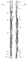
- the numeral 33 designates a perforating gun for well perforating having an elongated, spiraled mounting strip 35 having an outer diameter sized for convenient insertion and removal from a well that contains geological formations that are to be perforated to enhance the production of petroleum or other minerals.
- the spiral strip 35 is manufactured by utilizing the capabilities of a multiple axis laser milling machine on drawn-over-mandrel (DOM) tubing.
- the laser mill must have at least the X-axis and rotational capabilities in order to slit the spiral strip.
- Four (4) strips are manufactured from each full round tube started. The tube is left partially connected until all spiral slits are made over the length of the tube. The partial connection points are later broken apart to yield four (4) separate strips.
- the threaded holes on the strip are then completed on conventional machine centers.
- the perforating gun 33 has at its upper end a connector 37 for mounting on a conveyance sub (not shown) to raise or lower and position the gun at the selected elevation in the well adjacent to the geological formation to be perforated.
- the strip 35 is connected to a lower end of connector 47 with a plurality of fasteners 39 that may be socket head set screws or the equivalent.
- an electrical means 41 (see Fig. 5) adapted to supply electrical energy to a detonating cord 43.
- the exterior surface of the strip 35 is cylindrical about a longitudinal axis (not shown) and is formed of a selected metal that forms a helical band with a pitch in a range of 12 to 24 inches. As shown in the cross-sectional view of Figure 8A, a suitable thickness t for the strip is 0.125 inches and the circumferential width W 1.25 inches. At the lower end of the strip is connected a strap 45 to which may be secured a second spiraled strip 47. There are a series of openings in the spiraled strip 35 to serve as mounts for a plurality of explosive capsules 49. These openings are spaced in intervals along the length of the spiral strip so that they are arranged in a phase relationship to correspond with the selected perforation pattern in the well.
- each of the explosive capsules 49 has a cap 51 having a threaded nose 53 that engages the threads 55 of the strip 35.
- the cross-sectional area of the strip around or adjacent each opening is selected to prevent fragmentation of the strip 35 upon detonation of the charge, taking into account the strength of the material used to form the strip, which in the preferred embodiment is a strong, ductile and flexible material such as 1018 steel or 304 stainless steel.
- the cap 51 is hollow with an interior cavity 57 to receive an explosive charge and terminate in an angular interior thread 59 having a thread runout 61, as may be better seen in the enlarged, fragmentary view of Figure 9A.
- the thread runout 61 is wider than the threads 63 that are formed on the exterior of the open end of a hollow body 64 that partially contains the previously described explosive charge.
- the open end of the hollow body also has a seal 65 in an annular groove 67 to prevent contamination and degradation of the explosive charge.
- the opposite end of the hollow body 63 has a slot 69 to receive the detonating cord 43 shown in Figures 4 and 5, which is adjacent a heat-sensitive firing pin 71 that will detonate the explosive inside the capsule.
- a slot 73 receives a retainer clip 75 (see Fig. 8) of conventional configuration to secure the detonating cord in its position adjacent to firing pin 71.
- the numeral 101 designates drawn-over-mandrel (DOM) tube shown in the plane of the paper (not a true plan or frontal elevational view) from which four (4) non-linear zig-zag mounting strips can be manufactured from each full round of tube with the use of a multiple axes laser milling machine.
- One such strip 103 is shown with a plurality of apertures 105 over its non-linear zig-zag length, having edges 107, 109 defined by slitting the tubing 101 with the laser mill.
- the laser mill must have rotational capabilities in order to slit the tubing 101 and form the non-linear zig-zag strip.
- the tube is left partially connected until the non-linear zig-zag slits are made over the length of the tube.
- the partial connection points are later broken apart to yield four (4) separate non-linear zig-zag strips.
- the apertures 105 on the strip are then threaded and completed.
- the tube 101 is shown as if it were cut longitudinally and rolled into the plane of the paper, appearing to be a rectangle.
- the circumference is marked in degrees 111 at the bottom of the tube.
- the degrees are used to define the edges 107, 109 of the strip 103 and their geometric shape.
- the dotted lines 113 are imaginary lines that are used in designing the shape of the strip 103 and do not appear physically on the tube.
- the strip 103 is described as being non-linear and in a zig-zag pattern.
- the strip 103 has a wave form comprised of a first triangular wave having a half wave length l 1 and an amplitude a 1 . This wave intersects and is continued by a second wave having a half wave length l 2 and an amplitude a 2 .
- the waves can have a variety of forms such as triangular (as shown), square, rectangular or sinusoidal to provide some examples.
- the waves can be repeating or identical or may have differing lengths and amplitudes as shown.
- the wave form is selected to provide the requisite pattern of apertures 105 in which to mount shaped charge capsules and to maximize the number of strips 103 that may be cut from the tube 101.
- the shaped charges, when mounted in apertures 105 are arranged in a segment of a cylinder (or arc of a circle in a range of preferably 90-120 degrees) to match the cylindrical shape of the wall in the well to be perforated.
- the apertures 105 are preferably spaced from one another in a range of 12 to 24 inches.
- the material is the same as that indicated for the spiral strip of Figure 4, with a thickness of 0.125 inches.
- the dimensions for a successful strip are:
- the spiral strip 35 of Figure 4 can be configured to enable the orientation of explosive capsules in a wide variety of selected patterns, one of which is shown in Figure 6 in which the strip 35 is used to position the explosive capsule 49 and others like it to form perforation 77 through the metal casing 79 and into the geological formation 81.
- This pattern has a phase relationship as shown in Figure 7 wherein the perforation 77 is indicated by the corresponding point at zero degrees.
- the configuration of the spiral strip when constructed as indicated above, prevents it from fragmenting or major distortion that would prevent its retrieval from a wellbore after the explosive capsules are detonated.
- the spiral may be considered to be a three dimensional and continuous wave in a cylindrical boundary.
- the non-linear or waved strip 103 of Figure 10 is an alternate way to achieve many of the advantages of the spiral strip of Figure 4. It is especially advantageous when the pattern perforations need not extend 360 degrees. Since plural strips can be formed of one tube 107, manufacturing efficiencies are obtained.
Landscapes
- Life Sciences & Earth Sciences (AREA)
- Engineering & Computer Science (AREA)
- Geology (AREA)
- Mining & Mineral Resources (AREA)
- Physics & Mathematics (AREA)
- Environmental & Geological Engineering (AREA)
- Fluid Mechanics (AREA)
- General Life Sciences & Earth Sciences (AREA)
- Geochemistry & Mineralogy (AREA)
- Portable Nailing Machines And Staplers (AREA)
- Pressure Welding/Diffusion-Bonding (AREA)
- Drilling And Exploitation, And Mining Machines And Methods (AREA)
Description
Claims (5)
- A perforating gun (33) for carrying a plurality of explosives (43) connecting by a detonating cord (43) to perforate a section of a well in a selected pattern, comprising:whereby the strip may be positioned in the well, the explosives detonated to create perforations in the selected pattern and the strip retrieved from the well.an elongated strip (35) having an outer diameter sized for convenient entry and removal from a well;a series of openings (55) spaced in intervals along a length of the strip; anda number of shaped explosive charge capsules mounted by engagement in the openings in the strip so as to be in an angular phase relationship to correspond with said selected perforation pattern in the well; characterised in that:the cross-sectional area of the strip around each opening is selected to prevent fragmentation of the carrier upon detonation of the charges;the strip is of spiral form, non-linear zig zag form or wave form having an exterior surface which coincides with an imaginary cylinder when viewed from the top along a longitudinal axis; andthe explosive charge capsules are connected at one end to respective openings in the strip and extend interiorly of said imaginary cylinder;
- The gun of claim 1 wherein said strip is a metallic, helical band with a pitch in a range of 12 to 24 inches.
- The gun of claim 1 or 2 wherein said openings of the strip are threaded to receive the charge capsules.
- The gun of any one of claims 1 to 3 wherein each capsule comprises:whereby the hollow body may be freely spun to align said slot and retainer for convenient threading and connection of the detonating cord with the explosive capsule charge.a cap (51) having a threaded nose (53) for engagement with a respective threaded opening (55) of said strip, the cap being hollow to contain explosive and terminating in an annular, interior thread (59) with a thread run-out of selected (61) width;a hollow body (64) to contain said explosive and having an open end with exterior threads (63) having a width less than the width of the thread run-out in the cap to permit free spinning of the body in the cap after thread make-up;a slot (73) and retainer to receive a detonating cord on a closed end of the hollow body;
- The gun of any one of claims 1 to 3 wherein the strip is of zig zag or wave form and the exterior surface of the strip forms an arc of a circle having a range of about 90 to 120 degrees.
Applications Claiming Priority (5)
| Application Number | Priority Date | Filing Date | Title |
|---|---|---|---|
| US08/459,509 US5638901A (en) | 1995-06-02 | 1995-06-02 | Spiral strip perforating system |
| US459509 | 1995-06-02 | ||
| US626392 | 1996-03-29 | ||
| US08/626,392 US5662178A (en) | 1995-06-02 | 1996-03-29 | Wave strip perforating system |
| PCT/US1996/007556 WO1996038652A1 (en) | 1995-06-02 | 1996-05-31 | Spiral or wave strip perforating system |
Publications (3)
| Publication Number | Publication Date |
|---|---|
| EP0835359A1 EP0835359A1 (en) | 1998-04-15 |
| EP0835359A4 EP0835359A4 (en) | 1998-11-25 |
| EP0835359B1 true EP0835359B1 (en) | 2003-08-06 |
Family
ID=27039389
Family Applications (1)
| Application Number | Title | Priority Date | Filing Date |
|---|---|---|---|
| EP96916580A Expired - Lifetime EP0835359B1 (en) | 1995-06-02 | 1996-05-31 | Spiral or wave strip perforating system |
Country Status (5)
| Country | Link |
|---|---|
| US (1) | US5662178A (en) |
| EP (1) | EP0835359B1 (en) |
| DE (1) | DE69629376T2 (en) |
| DK (1) | DK0835359T3 (en) |
| WO (1) | WO1996038652A1 (en) |
Families Citing this family (15)
| Publication number | Priority date | Publication date | Assignee | Title |
|---|---|---|---|---|
| US5816343A (en) * | 1997-04-25 | 1998-10-06 | Sclumberger Technology Corporation | Phased perforating guns |
| US6253862B1 (en) | 1999-02-03 | 2001-07-03 | Baker Hughes Incorporated | Earth-boring bit with cutter spear point hardfacing |
| US6591911B1 (en) * | 1999-07-22 | 2003-07-15 | Schlumberger Technology Corporation | Multi-directional gun carrier method and apparatus |
| US6244157B1 (en) | 1999-08-03 | 2001-06-12 | The Ensign-Bickford Company | Wire carrier perforating gun |
| EP1409839B1 (en) * | 2001-06-29 | 2005-04-06 | Shell Internationale Researchmaatschappij B.V. | Method and apparatus for detonating an explosive charge |
| US20050109501A1 (en) * | 2003-11-26 | 2005-05-26 | Ludwig Wesley N. | Perforating gun with improved carrier strip |
| US20050247447A1 (en) * | 2004-05-10 | 2005-11-10 | Spring Roger L | Angled perforating device for well completions |
| US20050267521A1 (en) * | 2004-05-13 | 2005-12-01 | St. Jude Medical Puerto Rico B.V. | Collagen sponge for arterial sealing |
| US20060201371A1 (en) * | 2005-03-08 | 2006-09-14 | Schlumberger Technology Corporation | Energy Controlling Device |
| US20070034750A1 (en) * | 2005-08-10 | 2007-02-15 | Kns Associates, Inc. | Tubing mounting clip |
| US8347962B2 (en) | 2005-10-27 | 2013-01-08 | Baker Hughes Incorporated | Non frangible perforating gun system |
| US9520219B2 (en) * | 2006-06-06 | 2016-12-13 | Owen Oil Tools Lp | Retention member for perforating guns |
| US8276656B2 (en) * | 2007-12-21 | 2012-10-02 | Schlumberger Technology Corporation | System and method for mitigating shock effects during perforating |
| US8794335B2 (en) | 2011-04-21 | 2014-08-05 | Halliburton Energy Services, Inc. | Method and apparatus for expendable tubing-conveyed perforating gun |
| EP3283726B1 (en) * | 2015-04-14 | 2023-03-22 | Hunting Titan Inc. | Detonating cord retaining device |
Family Cites Families (16)
| Publication number | Priority date | Publication date | Assignee | Title |
|---|---|---|---|---|
| US2912930A (en) * | 1955-10-14 | 1959-11-17 | Welox Inc | Perforating assembly |
| US2927534A (en) * | 1956-02-06 | 1960-03-08 | Pgac Dev Company | Perforating device and method of perforating wells |
| US2960930A (en) * | 1957-04-03 | 1960-11-22 | Jet Res Ct Inc | Well perforating apparatus |
| US2965031A (en) * | 1957-10-11 | 1960-12-20 | Seismograph Service Corp | Well bore detector and perforating apparatus |
| FR2285593A1 (en) * | 1974-09-20 | 1976-04-16 | Schlumberger Inst System | SUPPORT OF HOLLOW LOADS FOR THE START-UP OF BOREHOES AND IN PARTICULAR GAS WELLS |
| US4074756A (en) * | 1977-01-17 | 1978-02-21 | Exxon Production Research Company | Apparatus and method for well repair operations |
| FR2488648A1 (en) * | 1980-08-12 | 1982-02-19 | Schlumberger Prospection | PERFORATION DEVICE FOR BORING |
| US4716833A (en) * | 1986-01-03 | 1988-01-05 | Jet Research Center, Inc. | Method of assembling a tanged charge holder |
| US4694754A (en) * | 1986-04-21 | 1987-09-22 | Jet Research Inc. | Multi-phase charge holder |
| US4885993A (en) * | 1988-02-17 | 1989-12-12 | Goex, Inc. | Shaped charge with bifurcated projection for detonating cord |
| US4961365A (en) * | 1988-07-28 | 1990-10-09 | Schlumberger Technology Corporation | Perforating gun with rotating charges including a mechanical link retaining mechanism |
| US4844167A (en) * | 1988-09-29 | 1989-07-04 | Conoco Inc. | Through-tubing perforating apparatus |
| US4875413A (en) * | 1988-11-30 | 1989-10-24 | Jet Research Center, Inc. | Apparatus for perforating wells |
| US4951744A (en) * | 1989-08-16 | 1990-08-28 | Schlumberger Technology Corporation | Angularly shaped unitary structured base strip comprised of a specific material adapted for phasing charges in a perforating gun |
| US5095999A (en) * | 1990-08-07 | 1992-03-17 | Schlumberger Technology Corporation | Through tubing perforating gun including a plurality of phased capsule charges mounted on a retrievable base strip via a plurality of shatterable support rings |
| US5241891A (en) * | 1992-09-17 | 1993-09-07 | Goex International, Inc. | Phaseable link carrier for explosive charge |
-
1996
- 1996-03-29 US US08/626,392 patent/US5662178A/en not_active Expired - Lifetime
- 1996-05-31 DE DE69629376T patent/DE69629376T2/en not_active Expired - Lifetime
- 1996-05-31 WO PCT/US1996/007556 patent/WO1996038652A1/en not_active Ceased
- 1996-05-31 DK DK96916580T patent/DK0835359T3/en active
- 1996-05-31 EP EP96916580A patent/EP0835359B1/en not_active Expired - Lifetime
Also Published As
| Publication number | Publication date |
|---|---|
| EP0835359A1 (en) | 1998-04-15 |
| MX9709363A (en) | 1998-08-30 |
| WO1996038652A1 (en) | 1996-12-05 |
| DE69629376D1 (en) | 2003-09-11 |
| EP0835359A4 (en) | 1998-11-25 |
| DK0835359T3 (en) | 2003-10-27 |
| DE69629376T2 (en) | 2004-06-24 |
| US5662178A (en) | 1997-09-02 |
Similar Documents
| Publication | Publication Date | Title |
|---|---|---|
| US5785130A (en) | High density perforating gun system | |
| US5662178A (en) | Wave strip perforating system | |
| US11719077B2 (en) | High density cluster based perforating system and method | |
| US5542480A (en) | Perforating gun with retrievable mounting strips | |
| CA2649728C (en) | High density perforating gun system producing reduced debris | |
| US5619008A (en) | High density perforating system | |
| US4583602A (en) | Shaped charge perforating device | |
| US4519313A (en) | Charge holder | |
| EP1448868B1 (en) | Internally orientated perforating system | |
| US5323684A (en) | Downhole charge carrier | |
| US6014933A (en) | Downhole charge carrier | |
| EP3633138A1 (en) | Zinc one piece link system | |
| US6591911B1 (en) | Multi-directional gun carrier method and apparatus | |
| US20050139352A1 (en) | Minimal resistance scallop for a well perforating device | |
| US20140083283A1 (en) | High Density Perforating Gun System Producing Reduced Debris | |
| US5638901A (en) | Spiral strip perforating system | |
| CA2565837C (en) | Non frangible perforating gun system | |
| US2750884A (en) | Blasting of underground formations | |
| CA2974013C (en) | Limited entry phased perforating gun system and method | |
| CA2222717C (en) | Spiral or wave strip perforating system | |
| EP0874130B1 (en) | Phased perforating guns | |
| MXPA97009363A (en) | Drilling system with strip in spiral uondul | |
| US20210207459A1 (en) | Multi-phase, single point, short gun perforation device for oilfield applications | |
| CA2312258A1 (en) | Unique phasings and filing sequences for perforating guns |
Legal Events
| Date | Code | Title | Description |
|---|---|---|---|
| PUAI | Public reference made under article 153(3) epc to a published international application that has entered the european phase |
Free format text: ORIGINAL CODE: 0009012 |
|
| 17P | Request for examination filed |
Effective date: 19971208 |
|
| AK | Designated contracting states |
Kind code of ref document: A1 Designated state(s): DE DK FR GB IE IT NL SE |
|
| A4 | Supplementary search report drawn up and despatched |
Effective date: 19981005 |
|
| AK | Designated contracting states |
Kind code of ref document: A4 Designated state(s): DE DK FR GB IE IT NL SE |
|
| 17Q | First examination report despatched |
Effective date: 20020305 |
|
| GRAH | Despatch of communication of intention to grant a patent |
Free format text: ORIGINAL CODE: EPIDOS IGRA |
|
| GRAH | Despatch of communication of intention to grant a patent |
Free format text: ORIGINAL CODE: EPIDOS IGRA |
|
| GRAA | (expected) grant |
Free format text: ORIGINAL CODE: 0009210 |
|
| RAP1 | Party data changed (applicant data changed or rights of an application transferred) |
Owner name: OWEN OIL TOOLS LP |
|
| AK | Designated contracting states |
Designated state(s): DE DK FR GB IE IT NL SE |
|
| REG | Reference to a national code |
Ref country code: GB Ref legal event code: FG4D |
|
| REG | Reference to a national code |
Ref country code: IE Ref legal event code: FG4D |
|
| REF | Corresponds to: |
Ref document number: 69629376 Country of ref document: DE Date of ref document: 20030911 Kind code of ref document: P |
|
| REG | Reference to a national code |
Ref country code: SE Ref legal event code: TRGR |
|
| ET | Fr: translation filed | ||
| PLBE | No opposition filed within time limit |
Free format text: ORIGINAL CODE: 0009261 |
|
| STAA | Information on the status of an ep patent application or granted ep patent |
Free format text: STATUS: NO OPPOSITION FILED WITHIN TIME LIMIT |
|
| 26N | No opposition filed |
Effective date: 20040507 |
|
| REG | Reference to a national code |
Ref country code: FR Ref legal event code: PLFP Year of fee payment: 20 |
|
| PGFP | Annual fee paid to national office [announced via postgrant information from national office to epo] |
Ref country code: DK Payment date: 20150512 Year of fee payment: 20 Ref country code: SE Payment date: 20150512 Year of fee payment: 20 Ref country code: DE Payment date: 20150527 Year of fee payment: 20 Ref country code: GB Payment date: 20150527 Year of fee payment: 20 |
|
| PGFP | Annual fee paid to national office [announced via postgrant information from national office to epo] |
Ref country code: IE Payment date: 20150512 Year of fee payment: 20 Ref country code: FR Payment date: 20150508 Year of fee payment: 20 Ref country code: IT Payment date: 20150515 Year of fee payment: 20 Ref country code: NL Payment date: 20150510 Year of fee payment: 20 |
|
| REG | Reference to a national code |
Ref country code: DE Ref legal event code: R071 Ref document number: 69629376 Country of ref document: DE |
|
| REG | Reference to a national code |
Ref country code: NL Ref legal event code: MK Effective date: 20160530 |
|
| REG | Reference to a national code |
Ref country code: DK Ref legal event code: EUP Effective date: 20160531 |
|
| REG | Reference to a national code |
Ref country code: GB Ref legal event code: PE20 Expiry date: 20160530 |
|
| REG | Reference to a national code |
Ref country code: IE Ref legal event code: MK9A |
|
| PG25 | Lapsed in a contracting state [announced via postgrant information from national office to epo] |
Ref country code: IE Free format text: LAPSE BECAUSE OF EXPIRATION OF PROTECTION Effective date: 20160531 Ref country code: GB Free format text: LAPSE BECAUSE OF EXPIRATION OF PROTECTION Effective date: 20160530 |
|
| REG | Reference to a national code |
Ref country code: SE Ref legal event code: EUG |