EP0834723A1 - Capteur thermique de débit massique et régulateur de débit massique, procédé et dispositif de mesure de débit - Google Patents
Capteur thermique de débit massique et régulateur de débit massique, procédé et dispositif de mesure de débit Download PDFInfo
- Publication number
- EP0834723A1 EP0834723A1 EP97630039A EP97630039A EP0834723A1 EP 0834723 A1 EP0834723 A1 EP 0834723A1 EP 97630039 A EP97630039 A EP 97630039A EP 97630039 A EP97630039 A EP 97630039A EP 0834723 A1 EP0834723 A1 EP 0834723A1
- Authority
- EP
- European Patent Office
- Prior art keywords
- fluid
- mass flow
- flow controller
- process fluid
- calibration
- Prior art date
- Legal status (The legal status is an assumption and is not a legal conclusion. Google has not performed a legal analysis and makes no representation as to the accuracy of the status listed.)
- Withdrawn
Links
Images


Classifications
-
- G—PHYSICS
- G01—MEASURING; TESTING
- G01F—MEASURING VOLUME, VOLUME FLOW, MASS FLOW OR LIQUID LEVEL; METERING BY VOLUME
- G01F1/00—Measuring the volume flow or mass flow of fluid or fluent solid material wherein the fluid passes through a meter in a continuous flow
- G01F1/68—Measuring the volume flow or mass flow of fluid or fluent solid material wherein the fluid passes through a meter in a continuous flow by using thermal effects
- G01F1/696—Circuits therefor, e.g. constant-current flow meters
- G01F1/6965—Circuits therefor, e.g. constant-current flow meters comprising means to store calibration data for flow signal calculation or correction
-
- G—PHYSICS
- G01—MEASURING; TESTING
- G01F—MEASURING VOLUME, VOLUME FLOW, MASS FLOW OR LIQUID LEVEL; METERING BY VOLUME
- G01F1/00—Measuring the volume flow or mass flow of fluid or fluent solid material wherein the fluid passes through a meter in a continuous flow
- G01F1/68—Measuring the volume flow or mass flow of fluid or fluent solid material wherein the fluid passes through a meter in a continuous flow by using thermal effects
- G01F1/684—Structural arrangements; Mounting of elements, e.g. in relation to fluid flow
- G01F1/6842—Structural arrangements; Mounting of elements, e.g. in relation to fluid flow with means for influencing the fluid flow
-
- G—PHYSICS
- G01—MEASURING; TESTING
- G01F—MEASURING VOLUME, VOLUME FLOW, MASS FLOW OR LIQUID LEVEL; METERING BY VOLUME
- G01F1/00—Measuring the volume flow or mass flow of fluid or fluent solid material wherein the fluid passes through a meter in a continuous flow
- G01F1/68—Measuring the volume flow or mass flow of fluid or fluent solid material wherein the fluid passes through a meter in a continuous flow by using thermal effects
- G01F1/684—Structural arrangements; Mounting of elements, e.g. in relation to fluid flow
- G01F1/6847—Structural arrangements; Mounting of elements, e.g. in relation to fluid flow where sensing or heating elements are not disturbing the fluid flow, e.g. elements mounted outside the flow duct
-
- G—PHYSICS
- G01—MEASURING; TESTING
- G01F—MEASURING VOLUME, VOLUME FLOW, MASS FLOW OR LIQUID LEVEL; METERING BY VOLUME
- G01F1/00—Measuring the volume flow or mass flow of fluid or fluent solid material wherein the fluid passes through a meter in a continuous flow
- G01F1/76—Devices for measuring mass flow of a fluid or a fluent solid material
- G01F1/86—Indirect mass flowmeters, e.g. measuring volume flow and density, temperature or pressure
-
- G—PHYSICS
- G01—MEASURING; TESTING
- G01F—MEASURING VOLUME, VOLUME FLOW, MASS FLOW OR LIQUID LEVEL; METERING BY VOLUME
- G01F15/00—Details of, or accessories for, apparatus of groups G01F1/00 - G01F13/00 insofar as such details or appliances are not adapted to particular types of such apparatus
- G01F15/02—Compensating or correcting for variations in pressure, density or temperature
- G01F15/022—Compensating or correcting for variations in pressure, density or temperature using electrical means
- G01F15/024—Compensating or correcting for variations in pressure, density or temperature using electrical means involving digital counting
-
- G—PHYSICS
- G01—MEASURING; TESTING
- G01F—MEASURING VOLUME, VOLUME FLOW, MASS FLOW OR LIQUID LEVEL; METERING BY VOLUME
- G01F25/00—Testing or calibration of apparatus for measuring volume, volume flow or liquid level or for metering by volume
- G01F25/10—Testing or calibration of apparatus for measuring volume, volume flow or liquid level or for metering by volume of flowmeters
- G01F25/13—Testing or calibration of apparatus for measuring volume, volume flow or liquid level or for metering by volume of flowmeters using a reference counter
-
- G—PHYSICS
- G01—MEASURING; TESTING
- G01F—MEASURING VOLUME, VOLUME FLOW, MASS FLOW OR LIQUID LEVEL; METERING BY VOLUME
- G01F25/00—Testing or calibration of apparatus for measuring volume, volume flow or liquid level or for metering by volume
- G01F25/10—Testing or calibration of apparatus for measuring volume, volume flow or liquid level or for metering by volume of flowmeters
- G01F25/15—Testing or calibration of apparatus for measuring volume, volume flow or liquid level or for metering by volume of flowmeters specially adapted for gas meters
-
- G—PHYSICS
- G01—MEASURING; TESTING
- G01F—MEASURING VOLUME, VOLUME FLOW, MASS FLOW OR LIQUID LEVEL; METERING BY VOLUME
- G01F5/00—Measuring a proportion of the volume flow
-
- G—PHYSICS
- G05—CONTROLLING; REGULATING
- G05D—SYSTEMS FOR CONTROLLING OR REGULATING NON-ELECTRIC VARIABLES
- G05D7/00—Control of flow
- G05D7/06—Control of flow characterised by the use of electric means
- G05D7/0617—Control of flow characterised by the use of electric means specially adapted for fluid materials
- G05D7/0629—Control of flow characterised by the use of electric means specially adapted for fluid materials characterised by the type of regulator means
- G05D7/0635—Control of flow characterised by the use of electric means specially adapted for fluid materials characterised by the type of regulator means by action on throttling means
-
- Y—GENERAL TAGGING OF NEW TECHNOLOGICAL DEVELOPMENTS; GENERAL TAGGING OF CROSS-SECTIONAL TECHNOLOGIES SPANNING OVER SEVERAL SECTIONS OF THE IPC; TECHNICAL SUBJECTS COVERED BY FORMER USPC CROSS-REFERENCE ART COLLECTIONS [XRACs] AND DIGESTS
- Y10—TECHNICAL SUBJECTS COVERED BY FORMER USPC
- Y10T—TECHNICAL SUBJECTS COVERED BY FORMER US CLASSIFICATION
- Y10T137/00—Fluid handling
- Y10T137/7722—Line condition change responsive valves
- Y10T137/7758—Pilot or servo controlled
- Y10T137/7759—Responsive to change in rate of fluid flow
-
- Y—GENERAL TAGGING OF NEW TECHNOLOGICAL DEVELOPMENTS; GENERAL TAGGING OF CROSS-SECTIONAL TECHNOLOGIES SPANNING OVER SEVERAL SECTIONS OF THE IPC; TECHNICAL SUBJECTS COVERED BY FORMER USPC CROSS-REFERENCE ART COLLECTIONS [XRACs] AND DIGESTS
- Y10—TECHNICAL SUBJECTS COVERED BY FORMER USPC
- Y10T—TECHNICAL SUBJECTS COVERED BY FORMER US CLASSIFICATION
- Y10T137/00—Fluid handling
- Y10T137/7722—Line condition change responsive valves
- Y10T137/7758—Pilot or servo controlled
- Y10T137/7761—Electrically actuated valve
Definitions
- This invention relates to mass rate of measurement fluid flowmeters and flow controllers, and more particularly, to an analog or digital flowmeter employed in manufacturing processes such as the manufacture of semiconductor chips in which highly toxic and highly reactive fluids are used, and because of which, such flowmeters are not calibrated using the fluid they will be controlling during a process.
- a reactive fluid is a gas which is corrosive, flammable, or pyrophoric, among other things.
- a reactive fluid for example, dichlorosilane (SiH 2 Cl 2 )
- SiH 2 Cl 2 dichlorosilane
- Process control in the critical process steps where these fluids are used is accomplished by monitoring the mass flow rate of the gas and controlling appropriate valving to adjust the flow to a desired rate for the process condition. Measuring mass flow rates is old in the art. Essentially it is done using either an analog measuring system, or a digital based system. Regardless of which technique is used, there has been, and until now, continues to be, substantial control problems which must be overcome in order to maintain a process capable of producing quality chips.
- a surrogate gas is one which has specific heat properties which are substantially close to a process gas with which the controller is used. Using a surrogate gas reduces the magnitude of the conversion factor required to adapt the instrument's performance to the process gas.
- a control system may include a central control computer which commands analog input/output (L/O) cards of a process controller.
- the I/O card converts digital signals from the computer to analog set point signals, and analog flow information signals to digital signals supplied to the computer.
- the system includes the following sources of potential signal error: wire and connector losses, noise pick-up, and analog-to-digital and digital-to-analog conversion errors.
- An important object of the present invention is the improvement in measurement accuracy which result from the flowmeter's or flow controller's calibration for a customer's process gas or gases.
- the calibration process now eliminates the need for "tweaking" by the user's technical personnel and the "cut and try” techniques previously used by such personnel to accommodate a calibrated flowmeter or flow controller to the particular process. The attendant costs and wastes arising from these techniques are now also eliminated, and process development time is shortened since these steps need no longer be performed.
- Another important object of the invention is the capability of the improved flowmeter or flow controller to be used in a variety of processes in which highly toxic, highly corrosive, or expensive gases, or some combination thereof are normally used. Even though flowmeter or flow controller calibration is performed on "safe" gases, the calibration is now such that the thermodynamic transport properties of such gases are taken into account as part of the calibration process.
- a further object of the invention is the provision of an improved flowmeter or flow controller in which either is independently calibrated for a number of gases with which they are used and the calibration information for each gas is stored within the instrument and is readily accessible by a user. The personnel using the controller now no longer need to maintain separate "little black books" containing relevant information necessary to adjust the instrument's operation, depending upon the gas currently being used in a process.
- An additional object of the invention is the creation and usage of a database which contains information relating performance of a flowmeter or flow controller with a gas used in a process as well as that of the instrument with a calibration gas or gases.
- the database enables the instrument to be readily used with process gases over the entire operating range of the instrument; that is, the instrument is readily used with any of the number of gases for which the instrument is calibrated, and for the entire range of flow rates of these gases in a particular process.
- a further object of the invention is to provide a flowmeter or mass flow controller having the capability to remotely zero the flow sensor used with the instrument.
- Other instrument capabilities include a digitally adjustable setpoint and ramprate, and temperature monitoring for indicating the temperature outside the instrument's flow rate sensor.
- direct indications can be provided of a sensor's raw output signals and a valve drive signal from the instrument so clogging or restriction of the sensor can be detected.
- the instruments can be interconnected so, for example, their setpoints can be simultaneously adjusted.
- a calibration gas N 2 for example
- a further object of the invention is to provide an instrument having stored data sets for various system operating pressures.
- the controller of the instrument is responsive to a pressure sensor reading or pressure input information from a process control to interpolate between data sets where the sensed pressure is intermediate the pressure values for which the data sets were produced.
- Yet another object of the invention is the establishment of a system of fluid flowmeters or flow controllers each of which independently functions within some part of a manufacturing process.
- the system includes a communications network by which each flowmeter or flow controller can separately, quickly access a database containing relevant information for use by the instrument. This enables each instrument to have the information readily available by which the instrument can readily and precisely monitor and/or control the fluid flow portion of the process with which it is associated.
- a flowmeter or mass flow controller is used in a manufacturing process such as for the manufacture of semiconductor chips.
- the flowmeter or mass flow controller meters, or meters and controls the flow of one of a variety of fluids used in the process, and a number of meters and/or controllers may be used with the same or different fluids.
- the process fluid is used in the process under a variety of temperature and pressure conditions. And, the fluids may be toxic, corrosive, or otherwise reactive.
- the mass flow meter comprises a fluid flow sensor for sensing fluid flow through a passage by which the fluid is directed to a portion of the process where it is used. The flow meter provides an output signal to the user that accurately represents the flow passing through the instrument at a given time.
- the instrument includes a processor which accesses stored calibration information derived for one or more process fluids the mass flowmeter measures and covers the operating range of the instrument.
- the signal from the flow sensor is processed by the instrument's processor using the calibration curve, temperature and pressure information to give an accurate indication of the flow rate.
- the mass flow controller comprises the same sensing and signal processing elements as the mass flowmeter with the addition of a valve drive that operates a fluid flow valve to control the mass flow rate of fluid into the process and a control unit.
- a set point is established by an external input supplied by the user to establish a desired flow rate for a process fluid.
- the control unit of the instrument operates the valve drive. To do this, the control unit includes a processor which accesses stored calibration information derived for one or more process fluids the mass flow controller controls and which covers the operating range of the instrument. From this calibration curve the fluid flow rate for the process fluid to be delivered by the valve is determined.
- the calibration information stored in the instrument is derived from calibration data for a calibration fluid which is not the process fluid whose flow is now being controlled, but which has similar thermodynamic transport properties.
- the calibration information is stored in a data base and the instrument's calibration is established for a particular process fluid by adapting the instrument's calibration curve for a calibration gas at certain set point conditions over the operating range of the instrument using the process fluid data stored in the data base.
- a system of process control employing multiple mass flowmeters and/or mass flow controllers in which set point information is supplied to each instrument, and a method of calibrating a flowmeter or mass flow controller with an inert fluid and adapting the resulting calibration curve so the instrument can be used for toxic, reactive process fluids are also disclosed.
- Other objects and features will be in part apparent and in part pointed out hereinafter.
- Fig. 1 represents a prior art analog mass flow controller (MFC) 10.
- MFC mass flow controller
- the functional components of the controller are implemented using resistors, potentiometers, capacitors, amplifiers, etc.
- a flow rate sensor 12 is a thermal sensor which, as is well-known in the art, converts the flow rate of a gas into an electrical voltage signal.
- the amplitude of this signal is a function of the thermal gradient (temperature difference) between an upstream and downstream monitoring location, and hence measured flow rate.
- a thermistor 14 is connected in series with windings (not shown) of the sensor to provide compensation for shifts in the sensor calibration resulting from temperature effects on a measurement. Use of the thermistor typically provides a linear or first order compensation.
- the full scale output voltage of sensor 12 is on the order of 50 mVDC.
- the sensor output is provided to a gain and linearization module 16 in which the analog output signal from the sensor is amplified, linearized, and then supplied to a junction point 18.
- Module 16 employs feedback to produce a linear output to the summing point and controller, filtering to eliminate noise effects on the output signal, and adjustable components potentiometers) for controller calibration.
- the output signal from module 16 is, for example, variable from 0-5VDC, and a setpoint input to the controller also varies between 0-5VDC.
- These signals are summed at junction point 18 and their difference is provided to a controller 20 which uses the difference value to determine the position of a fluid flow control valve V.
- the valve position is controlled by a valve drive 22 to which outputs from controller module 20 are provided.
- the controller module takes into account factors such as the established operating setpoint, and overshoot, undershoot, and steady-state operating conditions to determine the valve V position.
- Calibration of analog device 10 is performed by determining and adjusting the flow of a calibration fluid at three points within the metering range of the instrument. These points reflect 0%, 50%, and 100% of the instrument's scale range. Based upon the instrument's performance, the potentiometers within module 16 are adjusted so the resulting calibration curve is essentially as represented by the dashed line in Fig. 2. That is, they are adjusted to control the instrument's zero, span, and linearity. As can be seen in the Fig., the ideal curve is a straight line (the solid line) extending between the 0.0 and 100.100 co-ordinates on the curve. However, the calibration curve may have a positive or negative offset at the respective ends of the curve; i.e., at the higher and lower flow rates. It will be understood that the dashed line representation in the Fig. is exaggerated for purposes of understanding the performance capabilities of the instrument. The actual worst case error of a calibrated instrument is on the order of ⁇ 1% full scale.
- a prior art digital mass rate flow controller 30 includes a flow sensor 32 and a temperature sensor 34.
- ADC analog-to-digital converter
- ADC 36 is, for example, a twenty-four bit converter, as is ADC 38.
- the digital output from each converter is applied as a separate mathematical input to a microprocessor 40.
- Microprocessor 40 incorporates three elements. First is a microcontroller 42, second is a 64K by 8 erasable programmable read-only-memory, or EPROM 44, and third is a 4K by 8 EEPROM 46. Operating software for running controller 30 is stored in EPROM 44, and product information and calibration tables are stored in EEPROM 46.
- the software implemented in the microprocessor performs the linearization and filtering functions performed in module 16 of the analog controller 10, as well as the controller 20 functions of the analog instrument.
- the microprocessor has enhanced performance capabilities in these areas as well as the capability to provide performance outputs to the user on a timely basis.
- the control output from the microprocessor is a digital signal supplied to a digital-to-analog converter (DAC) 48 which produces an analog signal for valve drive 22 to open and close valve V.
- DAC digital-to-analog converter
- an analog and a digital flowmeter differ in that in an analog unit, the basic signal conditioning and control functions are performed using an operational amplifier (op-amp). In a digital unit, a microprocessor performs these functions. It will further be understood that in a flowmetering system, a digital flowmeter, for example, may be used with an analog communications system. Other variations are also possible depending upon the user's system in which a flowmeter or flow controller is installed.
- op-amp operational amplifier
- a digital flowmeter for example, may be used with an analog communications system.
- Other variations are also possible depending upon the user's system in which a flowmeter or flow controller is installed.
- Calibration of a digital flow controller differs significantly from the calibration of an analog flow controller.
- a full scale flow rate having an accuracy on the order of ⁇ 2% is produced.
- the flow controller is operated at a number of different set points (ten, for example) over the operating range of the instrument. Performance data is accumulated for each set point.
- An equation is now generated using the resulting text data. The equation represents the calibration curve for the instrument over the entire operating range of the instrument.
- a table of calibration points (twenty-five, for example) is created and stored in memory 46 of the controller.
- a plot of the flow rate vs. set point curve is illustrated in Fig. 4. The values displayed on the curve of Fig. 4 are corrected using temperature information from sensor 34.
- Memory 46 of controller 30 is capable of storing multiple calibration curves so the controller can be separately calibrated for multiple gases and multiple flow rates.
- a flowmeter of the present invention is indicated generally 100 and a flow controller 101.
- the flowmeter or flow controller can be used individually; or, as shown in Fig. 5, in a system having a plurality of other flowmeters and flow controllers indicated MFC2..MFCn.
- respective flowmeters and flow controllers are in communication with a process control 102 is used to monitor the process and to establish set point conditions for each instrument.
- flowmeter 100 which is shown to be a digital flowmeter, is connected to a fluid flow control portion of a process 104.
- the portion of the process with which flowmeter 100 is associated includes a fluid flow passage 106, an inlet 108 to the passage, an outlet 110 from the passage, and a bypass 112 through which a portion of the process fluid flows.
- bypass 112 is also referred to as a restrictor, flow shunt, or flow splitter.
- Fluid flow through bypass 112 is monitored by a flow sensor 114 of the flowmeter, and by a temperature sensor 116.
- a pressure sensor 117 may also be used by the instrument.
- the fluid flow information gathered by sensor 114 is an analog signal output to an A/D converter 118.
- the output of temperature sensor 116 (or pressure sensor 117) is an analog output which is provided as an input to an A/D converter 120.
- the digital signal outputs of the A/D converters are supplied to a microprocessor 122 of the flowmeter.
- Stored within a memory portion of the microprocessor are a series of data sets representing calibration curves developed for the instrument using data developed specifically for the process fluids with which the flowmeter or flow controller is used and for specific fluid pressure and fluid flow conditions.
- the microprocessor utilizing the data set or fluid calibration curve for established set point conditions for the process, and the process fluid flow data, is now able to generate a fluid flow signal by which accurate flow rates are achieved.
- the result is the production of a control signal for a valve drive 124 by which the valve drive can open or close a flow control valve 126 and precisely control process fluid flow through the passage.
- the control signal from microprocessor 122 is a digital signal supplied to a D/A converter 128 to produce an analog signal used by valve drive 124.
- the flow charts of the Figs. set forth how a determination is made as whether or not a flowmeter 100 or mass flow controller 101 is to be used with a process fluid for which flow control data exists, whether or not flow data for a particular process fluid is already stored in a data base; and, if not, how flow control data for the process fluid is developed, stored in the data base, and used to create a data set stored in a memory portion of microprocessor 122 of the instrument.
- the order typically includes a set of operating criteria in which the instrument will be used to control flow rate of a process fluid.
- This criteria includes the process fluids with which the controller will be used, as well as the flow range, and temperature and pressure conditions.
- a determination is therefore first made as to whether flow control information for the fluid or fluids and the range of operating conditions are currently in the data base. This is step S2 in Fig. 6. If so, the next determination is whether the flowmeter or mass flow controller will be an analog or digital instrument. This occurs at step S3.
- the instrument is an analog instrument, then the instrument is constructed and a calibration is performed on the instrument using nitrogen gas, for example. This calibration is then matched to a companion curve generated from the stored flow data for the process fluid. This is step S4. At step S5, a quality control check is performed to verify that the companion curve does match. If there is verification, then the instrument is shipped as indicated at step S6.
- the instrument is constructed and calibrated. Again, nitrogen gas is the calibration fluid. Now, a scaling or conversion factor is used to determine full scale flow of nitrogen and a conversion factor equation is developed based on the calibration results. Generation of the scaling factor is discussed hereafter.
- the conversion factor equation is stored in the microprocessor memory of the instrument.
- the equation is used to produce a calibration for the instrument for the process gas with which the controller is used, and the given set of operating conditions.
- a quality control check is made of the instrument. This is step S9. If successful, the digital mass flow controller is shipped.
- step S10 it is determined if there is any flow data for a particular process fluid; and if so, what are the "bounding" conditions for the data. That is, what are the temperature and pressure conditions for which flow data was obtained, and how closely do these bounding conditions approximate those under for which the instrument will be used with the fluid. If there is no relevant information, then data base information will be developed at step S11 and as discussed with reference to Fig. 7. If there is bounding information for the process gas as indicated at step S12, a conversion factor is developed by which a companion curve can be generated for use in the instrument's calibration. This is the conversion factor used at step S8 in the calibration of a digital mass flow controller.
- step S11 involves generation of process fluid information for inclusion in a data base.
- the data is accumulated for a variety of process fluids for a range of operating conditions.
- the threshold question to be asked is what data to collect.
- Step S14 is the information requested by the customer for the process gases and sets of conditions under which the gas will be used.
- Step S14 includes the calibration information normally generated by the instrument manufacturer. That is, the manufacturer will have a standard calibration procedure (or procedures) which is normally performed on each instrument. From the information gathered at steps S14 and S15, an overall calibration plan for the instrument is defined at step S16. This information now includes all of the process fluids with which the instrument will possibly be used, full scale flow values, and the range of temperature and pressure conditions for the various process fluids.
- the manufacturer builds a number of instruments as indicated at step S17. By building a minimum number of instruments, statistical validity of the instruments' calibration can be determined.
- the instruments are then calibrated. Part of this procedure includes ranging the full scale output for a calibration gas equivalent of the actual (process) gas for given sets of conditions. That is, obtaining data for the defined range of conditions using a gas having thermodynamic transport properties which closely match those of the process fluid.
- the instruments are transported (step S19) to a calibration installation which has facilities to develop the flow data for the process fluids with which the instruments are used.
- the instruments are separated into analog and digital groupings.
- an actual gas calibration is performed using a process fluid at each of a set of pressure and temperature conditions (i.e., P1-T1, P2-T2,...Pn-Tn). This is step S21.
- a calibration check procedure is performed using a calibration gas at the same pressure conditions as the process gas and the calibration gas calibration data is compared against that obtained for the process fluids.
- the instruments are then returned to the manufacturer (step S23) where calibration tests are made at the various pressure conditions using the calibration gas (step S24).
- step S25 The resulting calibration data is now checked (step S25) and if the results correlate with those from the testing facility, the flow data for the process fluid for the given sets of conditions are entered into a data base 200 established for this purpose. If the results do not correlate, then the process set out in steps S20-S24 is repeated.
- step S26 data for the actual gas is collected at specific set point (temperature and pressure) conditions. If additional testing is desired, in order to obtain bounding conditions for performance predictions, then further actual gas testing is performed for additional conditions (step S27). If no additional testing is done, then a calibration check (similar to that performed at step S22 for analog controllers) is performed (step S29). Thereafter, the instruments are returned to the manufacturer (step S30) for the manufacturer to perform a calibration check at his facility (step S31). Again, if the calibrations check out, the data is incorporated in data base 200. If not, steps S25-S31 are repeated.
- one or more data sets can be created for each flowmeter or mass flow controller, not only for each process fluid with which the instrument is used, but for the range of flow conditions which will be experienced in carrying out the process with which the fluid is used.
- These data sets are represented by stored calibration curves.
- the control means of the instrument can access the appropriate data set to provide the appropriate flow control signal to the valve means for sensed temperature and/or pressure conditions. This capability eliminates the need for external manipulation of process temperature and pressure data, to provide flow control inputs into the process.
- the data base 200 it can be updated, amended, etc. as additional process fluid information is collected. This not only improves the quality of instrument calibration, but reduces the time and cost involved in performing a calibration.
- Figs. 8A and 8B there is presented a simplified calibration/linearization method for a digital flowmeter or mass flow controller.
- 1 2 3 4 5 6 Set point and Raw Signal Measured Flow, N2 Curve fit N2 Flow Desired Flow, N2 Desired Signal N2 as gas Signal in Engr. Units, N2 0.000 0 0 0 0.000 0 0.625 160 125 0.488 125 1.250 320 320 250 0.977 250 1.875 470 375 1.496 375 2.500 600 600 500 2.083 500 3.125 700 625 2.790 625 3.750 800 800 750 3.516 750 4.375 900 875 4.253 875 5.000 1000 1000 1000 5.000 1000
- the curve shown in Fig. 8A is plotted for flow volume in standard cubic centimeters per minute as the abscissa and a set point and raw signal value as the ordinate.
- the range for the set point is from 0.0 to 5.0, and five points are plotted to generate the curve.
- the set point values are listed in column 1 of the chart, the five plotted points in column 2.
- the curve fit flow values listed in column 3 are taken directly from the plot.
- Fig. 8B illustrates a calibration curve for a digital flowmeter or flow controller in which the ordinate is the same as in Fig. 8A.
- the abscissa is for a desired signal and represents a modified set point value. These value are derived from the measured flow data for a set point as follows:
- Desired signal (desired flow/curve fit flow)*raw signal
- the desired flow value in column 4 is 125
- the curve fit flow value in column 3 is 160.
- the desired signal is expressed in engineering units. The values in this column are arrived at by multiplying the desired signal value in column 5 by a gas scaling factor. The values calculated for columns 5 and 6 now represent stored calibration data.
- the calibration is linear fit between adjacent points.
- the table of data points for this curve are stored in the memory portion of the microprocessor for the instrument. Now, when a set point is established, the desired signal representing measured flow of the process fluid for that set point can be found in a look up table in the memory. Thus, as illustrated in Fig. 8B, for a set point of 4.000, the desired signal can be readily established. Here, it is approximately 3.850.
- a calibration performed on a digital flowmeter first compnses performing the steps involved in collecting the measured flow data set out in column 2 of the table, using nitrogen gas, for the set point conditions listed in column 1 of the table. As in the previously described calibration, a curve fit is made using the measured flow data. The resulting fitted curve is indicated C1 in Fig. 9A. Next, similar data is gathered for a process gas, the actual gas (AG), with which the digital flow meter would be used, and a calculated AG curve is generated as indicated by curve C2 in Fig. 9A.
- curve X1 is a plot of the measured flow data for the actual gas
- curve X2 the measured flow data for the N2 gas.
- These plots are measured on the average measured flow values listed in columns B and C of table 3.
- the values respectively listed in columns D and E are the flow values for the set point values of column A, as taken from curves X1 and X2.
- the ratio values listed in column F of the table are arrived at by dividing the value for actual gas flow listed in column D by the N2 flow value in column E.
- the actual gas flow value 300 divided by the corresponding value 320 for N2 gas yields a ratio of 0.938.
- a curve X3 shown in Fig. 10B is a plot of the calculated ratios shown in column F.
- the actual gas and nitrogen or calibration gas values listed in table 3, and the calculated ratio values are stored in the data base now used for mass flow controller calibration.
- desired flow values for the actual gas are listed.
- desired signal (desired flow/curve fit flow)*(raw signal)
- the resultant value is entered in column 7. After these values are produced, the curve C3 shown in Fig. 9B is generated. Also, and as listed in column 8 of the table, the signal in engineering units for the actual gas can be created by multiplying the desired signal values of column, 7 by a gas scaling factor.
- the microprocessor 122 has stored therein data sets of process fluid calibration information which effectively comprises a series of curves C3. These curves are for all the process gases with which the controller is used and allows the instrument to provide accurate flow control for each of the process gases for the entire range of set point conditions with which may be encountered by the instrument as part of the process.
- Each of the other digital mass flow controllers MFC2-MFCn is similarly calibrated for the process fluids with which they are used.
- the process control 102 to which each of the mass flow controllers is connected provides updated set point and other relevant information to each of the units. The process control can poll each separate instrument to obtain status and other pertinent information used to control the process.
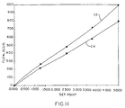
- the data in column 2 of table 4 represents average measured flow data for the actual process gas. After linearization, the data is plotted as shown by curve C4 in Fig. 11, and listed in column 3 of the table. After data has been similarly acquired for the calibration gas, the process steps previously described with respect to digital instrument calibrations are performed. The result is the curve C5 in Fig. 11 and the data points listed in column 5 of the table.
- the digital flow meters MFC1-MFCn shown in Fig. 5, could be analog flow meters with the same process control capability being realizable.
- the flow controllers could be connected in a communications system with a process control whereby the process control is able to provide set point and other relevant information to each controller and receive current process fluid flow information in return.
- a further advantage of the invention is the establishment of an improved, digital communications system 300 for routing information to and from the process control and individual instruments.
- This digital system eliminates signal errors resulting from noise and other effects. Elimination of such errors increases the precision with which the process is controlled thereby increasing the quality of the product produced by the process.
- the instrument has both improved signal processing and digital communications capabilities, and can be specifically calibrated for the manufacturing process in which it will be used. It is a particular advantage of the method of the invention to quickly and efficiently calibrate digital and analog flowmeters and mass flow controllers, and to do so at a reasonable cost while providing a high precision instrument such as is needed in certain manufacturing processes. Additionally, the complexity of signaling and controlling a process is reduced because of the improved system's communications. Overall, monitoring and control capabilities are increased which produces savings in process costs for the manufacture of articles such as semiconductor devices.
- Calibration is based upon a particular customer's process gas or gases and eliminates the "tweaking" and “cut and try” techniques now used to accommodate an instrument to a particular application.
- calibration is done using "safe” gases, instead of the highly toxic and highly reactive gases with which an instrument is actually used, the thermodynamic transport properties of such gases are readily taken into account during calibration.
- Representative units are independently calibrated for each of a number of gases with which it is used, with the calibration information of each gas stored within a memory of a flowmeter or flow controller, the instrument having sufficient data storage capability so all relevant instrument and calibration data is stored in the instrument and is readily accessible by the user.
- a database is created containing information relating to a unit's operation with a gas as well to that of the calibration gases.
- the database enables calibration accuracy to be consistent over the unit's entire operating range, regardless of which gas with which the instrument is used, and the entire range of gas flow rates.
- the improved instrument also has a remote capability, a digitally adjustable setpoint and ramprate, and temperature monitoring for indicating the temperature outside the instrument's flow rate sensor.
- a direct indication is also provided of the raw sensor signal and valve drive signal to detect sensor clogging or restriction.
- Multiple flow controllers can be interconnected into a flowmetering system for facilitating process control wherein each flowmeter is able to access the database to obtain information pertinent to just that flowmeter to enable each flowmeter to separately regulate fluid flow in respective areas of the process.
Applications Claiming Priority (2)
| Application Number | Priority Date | Filing Date | Title |
|---|---|---|---|
| US725859 | 1991-07-02 | ||
| US08/725,859 US5911238A (en) | 1996-10-04 | 1996-10-04 | Thermal mass flowmeter and mass flow controller, flowmetering system and method |
Publications (1)
| Publication Number | Publication Date |
|---|---|
| EP0834723A1 true EP0834723A1 (fr) | 1998-04-08 |
Family
ID=24916253
Family Applications (1)
| Application Number | Title | Priority Date | Filing Date |
|---|---|---|---|
| EP97630039A Withdrawn EP0834723A1 (fr) | 1996-10-04 | 1997-06-20 | Capteur thermique de débit massique et régulateur de débit massique, procédé et dispositif de mesure de débit |
Country Status (4)
| Country | Link |
|---|---|
| US (1) | US5911238A (fr) |
| EP (1) | EP0834723A1 (fr) |
| JP (1) | JPH10111152A (fr) |
| CA (1) | CA2202293C (fr) |
Cited By (36)
| Publication number | Priority date | Publication date | Assignee | Title |
|---|---|---|---|---|
| EP0890828A1 (fr) * | 1997-07-08 | 1999-01-13 | Emerson Electric Co. | Méthode et appareil pour détecter et contrÔler un débit massique |
| GB2332549A (en) * | 1997-12-22 | 1999-06-23 | Smc Kk | Electropneumatic regulator system |
| WO2000057139A1 (fr) * | 1999-03-24 | 2000-09-28 | Comalco Aluminium Limited | Mesure et commande du debit de materiaux fluides |
| WO2001004715A1 (fr) * | 1999-07-09 | 2001-01-18 | Millipore Corporation | Systeme et procede de commande d'un regulateur numerique de debit massique |
| WO2001004582A1 (fr) * | 1999-07-09 | 2001-01-18 | Millipore Corporation | Systeme et procede de linearisation de reponse de detecteur |
| EP1135716A1 (fr) * | 1998-10-08 | 2001-09-26 | Mott Metallurgical Corporation | Regulation de debit de fluide |
| WO2002069065A2 (fr) * | 2001-02-28 | 2002-09-06 | Porter Instrument Company, Inc. | Regulateur de debit |
| WO2002077577A1 (fr) * | 2001-03-26 | 2002-10-03 | Sit La Precisa S.P.A. | Dispositif destine a mesurer le debit gazeux, notamment pour des bruleurs |
| EP1249688A2 (fr) * | 2001-04-11 | 2002-10-16 | Hitachi, Ltd. | Débitmètre pour gaz |
| WO2002086632A2 (fr) * | 2001-04-24 | 2002-10-31 | Unit Instruments, Inc. | Systeme et procede destines a un controleur a debit massique |
| US6539792B2 (en) | 2000-02-14 | 2003-04-01 | Unit Instruments | Method and apparatus for balancing resistance |
| EP1314966A1 (fr) * | 2000-07-31 | 2003-05-28 | Mitsui Mining & Smelting Co., Ltd. | Procede de mesure de debit et debitmetre |
| WO2004010234A2 (fr) * | 2002-07-19 | 2004-01-29 | Celerity Group, Inc. | Procede et appareil de compensation de pression dans un controleur de debit massique |
| EP1396773A1 (fr) * | 2002-09-04 | 2004-03-10 | HR Textron Inc. | Soupape à entraínement direct commandée numériquement, et système et méthode de production d'une telle soupape |
| US6712084B2 (en) | 2002-06-24 | 2004-03-30 | Mks Instruments, Inc. | Apparatus and method for pressure fluctuation insensitive mass flow control |
| WO2004046840A1 (fr) * | 2002-11-20 | 2004-06-03 | Air Products And Chemicals, Inc. | Regulateur de debit-volume |
| WO2004088256A2 (fr) * | 2003-03-26 | 2004-10-14 | Celerity Inc. | Conversion de signal de capteur de flux |
| US6810308B2 (en) | 2002-06-24 | 2004-10-26 | Mks Instruments, Inc. | Apparatus and method for mass flow controller with network access to diagnostics |
| US6845659B2 (en) | 2002-07-19 | 2005-01-25 | Celerity Group, Inc. | Variable resistance sensor with common reference leg |
| US6868862B2 (en) | 2002-06-24 | 2005-03-22 | Mks Instruments, Inc. | Apparatus and method for mass flow controller with a plurality of closed loop control code sets |
| EP1523664A1 (fr) * | 2002-05-24 | 2005-04-20 | Mykrolis Corporation | Systeme et procede pour etalonner un dispositif de sondage de debit massique |
| US6948508B2 (en) | 2002-06-24 | 2005-09-27 | Mks Instruments, Inc. | Apparatus and method for self-calibration of mass flow controller |
| US7004191B2 (en) | 2002-06-24 | 2006-02-28 | Mks Instruments, Inc. | Apparatus and method for mass flow controller with embedded web server |
| GB2419677A (en) * | 2002-06-24 | 2006-05-03 | Mks Instr Inc | Pressure fluctuation insensitive mass flow controller |
| US7136767B2 (en) | 2002-06-24 | 2006-11-14 | Mks Instruments, Inc. | Apparatus and method for calibration of mass flow controller |
| EP1779073A1 (fr) * | 2004-08-13 | 2007-05-02 | Entegris, Inc. | Systeme et procede d'etalonnage d'un dispositif d'ecoulement |
| EP1975576A1 (fr) * | 2007-03-30 | 2008-10-01 | Dresser Wayne AB | Étalonnage de système de débitmètre |
| US7543595B2 (en) * | 2002-06-28 | 2009-06-09 | Siemens Building Technologies, Inc. | Valve calibration method and apparatus |
| US7552015B2 (en) | 2002-06-24 | 2009-06-23 | Mks Instruments, Inc. | Apparatus and method for displaying mass flow controller pressure |
| US7636640B2 (en) | 2006-09-05 | 2009-12-22 | Brooks Instrument, Llc | Multi-gas flow device |
| EP2163863A1 (fr) * | 2008-09-12 | 2010-03-17 | Yamatake Corporation | Débitmètre et dispositif de contrôle du volume d'écoulement |
| US7905139B2 (en) | 2008-08-25 | 2011-03-15 | Brooks Instrument, Llc | Mass flow controller with improved dynamic |
| EP2343517A1 (fr) | 2010-01-07 | 2011-07-13 | Sensirion AG | Procédé pour l'étalonnage d'un capteur de flux et un agencement de capteur de flux |
| US8738187B2 (en) | 2002-06-24 | 2014-05-27 | Mks Instruments, Inc. | Apparatus and method for pressure fluctuation insensitive mass flow control |
| AT522357A1 (de) * | 2019-03-18 | 2020-10-15 | Avl List Gmbh | Messsystem zur Messung eines Massendurchflusses, einer Dichte, einer Temperatur und/oder einer Strömungsgeschwindigkeit |
| WO2023180095A1 (fr) * | 2022-03-21 | 2023-09-28 | Belimo Holding Ag | Procédé et dispositifs de commande d'un système de commande d'écoulement |
Families Citing this family (91)
| Publication number | Priority date | Publication date | Assignee | Title |
|---|---|---|---|---|
| US6078030A (en) * | 1998-09-09 | 2000-06-20 | Millipore Corporation | Component heater for use in semiconductor manufacturing equipment |
| EP1096351A4 (fr) * | 1999-04-16 | 2004-12-15 | Fujikin Kk | Dispositif d'alimentation en fluide du type derivation parallele, et procede et dispositif de commande du debit d'un systeme de pression du type a fluide variable utilise dans ledit dispositif |
| US6389364B1 (en) * | 1999-07-10 | 2002-05-14 | Mykrolis Corporation | System and method for a digital mass flow controller |
| WO2001052215A1 (fr) | 2000-01-14 | 2001-07-19 | The Holmes Group, Inc. | Systeme de surveillance de filtre utilisant un thermistor |
| US20030183018A1 (en) * | 2000-06-05 | 2003-10-02 | Addink John W. | Flow meter as an irrigation management tool |
| AU2002224569A1 (en) | 2000-07-08 | 2002-02-05 | Fugasity Corporation | Fluid mass flow control valve and method of operation |
| AU2001277984A1 (en) * | 2000-07-25 | 2002-02-05 | Fugasity Corporation | Small internal volume fluid mass flow control apparatus |
| US6596059B1 (en) * | 2000-09-12 | 2003-07-22 | Skyline Products, Inc. | Automated filter changing device and method |
| US6539968B1 (en) | 2000-09-20 | 2003-04-01 | Fugasity Corporation | Fluid flow controller and method of operation |
| US6755210B2 (en) * | 2000-12-28 | 2004-06-29 | Mks Japan, Inc. | Mass flow controller |
| KR100401163B1 (ko) * | 2001-03-30 | 2003-10-17 | 이명의 | 자동 캘리브레이션 알고리즘을 이용한 하이브리드질량유량제어방법 및 장치 |
| US6564824B2 (en) * | 2001-04-13 | 2003-05-20 | Flowmatrix, Inc. | Mass flow meter systems and methods |
| JP2003099132A (ja) * | 2001-09-20 | 2003-04-04 | Smc Corp | 電空レギュレータ |
| ATE395652T1 (de) * | 2001-10-12 | 2008-05-15 | Horiba Stec Inc | System und verfahren zur herstellung und verwendung einer massenströmungseinrichtung |
| US6711956B2 (en) * | 2001-10-31 | 2004-03-30 | Macronix International Co., Ltd. | Method and apparatus for regulating exhaust pressure in evacuation system of semiconductor process chamber |
| US20030085714A1 (en) * | 2001-11-05 | 2003-05-08 | Keyes Marion A. | Mass flow control in a process gas analyzer |
| US6725167B2 (en) * | 2002-01-16 | 2004-04-20 | Fisher Controls International Llc | Flow measurement module and method |
| US6736005B2 (en) | 2002-05-28 | 2004-05-18 | Mcmillan Company | High accuracy measuring and control of low fluid flow rates |
| US7000464B2 (en) | 2002-05-28 | 2006-02-21 | Mcmillan Company | Measuring and control of low fluid flow rates with heated conduit walls |
| WO2004010087A2 (fr) * | 2002-07-19 | 2004-01-29 | Celerity Group, Inc | Debitmetre |
| TWI386578B (zh) | 2003-01-17 | 2013-02-21 | Applied Materials Inc | 避免一質量流量控制器涉及一質量流量控制器陣列中之干擾的方法 |
| US6926775B2 (en) * | 2003-02-11 | 2005-08-09 | Micron Technology, Inc. | Reactors with isolated gas connectors and methods for depositing materials onto micro-device workpieces |
| US7335396B2 (en) * | 2003-04-24 | 2008-02-26 | Micron Technology, Inc. | Methods for controlling mass flow rates and pressures in passageways coupled to reaction chambers and systems for depositing material onto microfeature workpieces in reaction chambers |
| US7003417B2 (en) * | 2003-06-06 | 2006-02-21 | Invensys Systems, Inc. | Multiple calibration ranges stored in a process transmitter |
| US7422635B2 (en) * | 2003-08-28 | 2008-09-09 | Micron Technology, Inc. | Methods and apparatus for processing microfeature workpieces, e.g., for depositing materials on microfeature workpieces |
| US7056806B2 (en) | 2003-09-17 | 2006-06-06 | Micron Technology, Inc. | Microfeature workpiece processing apparatus and methods for controlling deposition of materials on microfeature workpieces |
| US20050120805A1 (en) * | 2003-12-04 | 2005-06-09 | John Lane | Method and apparatus for substrate temperature control |
| US7437944B2 (en) * | 2003-12-04 | 2008-10-21 | Applied Materials, Inc. | Method and apparatus for pressure and mix ratio control |
| US7258892B2 (en) | 2003-12-10 | 2007-08-21 | Micron Technology, Inc. | Methods and systems for controlling temperature during microfeature workpiece processing, e.g., CVD deposition |
| US8133554B2 (en) | 2004-05-06 | 2012-03-13 | Micron Technology, Inc. | Methods for depositing material onto microfeature workpieces in reaction chambers and systems for depositing materials onto microfeature workpieces |
| US7699932B2 (en) | 2004-06-02 | 2010-04-20 | Micron Technology, Inc. | Reactors, systems and methods for depositing thin films onto microfeature workpieces |
| US7117104B2 (en) * | 2004-06-28 | 2006-10-03 | Celerity, Inc. | Ultrasonic liquid flow controller |
| US7216019B2 (en) * | 2004-07-08 | 2007-05-08 | Celerity, Inc. | Method and system for a mass flow controller with reduced pressure sensitivity |
| US7412986B2 (en) * | 2004-07-09 | 2008-08-19 | Celerity, Inc. | Method and system for flow measurement and validation of a mass flow controller |
| US9921089B2 (en) | 2005-06-27 | 2018-03-20 | Fujikin Incorporated | Flow rate range variable type flow rate control apparatus |
| US9383758B2 (en) | 2005-06-27 | 2016-07-05 | Fujikin Incorporated | Flow rate range variable type flow rate control apparatus |
| JP4856905B2 (ja) * | 2005-06-27 | 2012-01-18 | 国立大学法人東北大学 | 流量レンジ可変型流量制御装置 |
| TW200739039A (en) * | 2005-08-12 | 2007-10-16 | Celerity Inc | Ultrasonic flow sensor |
| KR100755297B1 (ko) | 2005-12-02 | 2007-09-05 | 주식회사 우일하이테크 | 제어밸브 일체형 차압식 유량계 |
| JP2008039513A (ja) * | 2006-08-03 | 2008-02-21 | Hitachi Metals Ltd | 質量流量制御装置の流量制御補正方法 |
| US7775236B2 (en) | 2007-02-26 | 2010-08-17 | Applied Materials, Inc. | Method and apparatus for controlling gas flow to a processing chamber |
| US7846497B2 (en) * | 2007-02-26 | 2010-12-07 | Applied Materials, Inc. | Method and apparatus for controlling gas flow to a processing chamber |
| US8074677B2 (en) | 2007-02-26 | 2011-12-13 | Applied Materials, Inc. | Method and apparatus for controlling gas flow to a processing chamber |
| JP2010169657A (ja) * | 2008-12-25 | 2010-08-05 | Horiba Stec Co Ltd | 質量流量計及びマスフローコントローラ |
| US8671973B2 (en) * | 2009-01-21 | 2014-03-18 | Hitachi Metals, Ltd. | Mass flow controller hysteresis compensation system and method |
| US8195312B2 (en) * | 2009-08-27 | 2012-06-05 | Hitachi Metals, Ltd | Multi-mode control loop with improved performance for mass flow controller |
| CN102576231B (zh) * | 2009-12-25 | 2015-04-15 | 株式会社堀场Stec | 质量流量控制器系统及控制设备 |
| JP2012033150A (ja) * | 2010-06-30 | 2012-02-16 | Toshiba Corp | マスフローコントローラ、マスフローコントローラシステム、基板処理装置およびガス流量調整方法 |
| JP5864849B2 (ja) | 2010-10-20 | 2016-02-17 | 株式会社堀場エステック | 流体計測システム |
| US8700221B2 (en) | 2010-12-30 | 2014-04-15 | Fluid Handling Llc | Method and apparatus for pump control using varying equivalent system characteristic curve, AKA an adaptive control curve |
| JP5915043B2 (ja) * | 2011-04-01 | 2016-05-11 | 日立金属株式会社 | 流量制御装置 |
| US9188989B1 (en) | 2011-08-20 | 2015-11-17 | Daniel T. Mudd | Flow node to deliver process gas using a remote pressure measurement device |
| US9958302B2 (en) | 2011-08-20 | 2018-05-01 | Reno Technologies, Inc. | Flow control system, method, and apparatus |
| JP5809012B2 (ja) * | 2011-10-14 | 2015-11-10 | 株式会社堀場エステック | 流量制御装置、流量測定機構、又は、当該流量測定機構を備えた流量制御装置に用いられる診断装置及び診断用プログラム |
| JP5803552B2 (ja) * | 2011-10-14 | 2015-11-04 | 東京エレクトロン株式会社 | 処理装置 |
| RU2611071C2 (ru) * | 2011-12-16 | 2017-02-21 | Флюид Хэндлинг ЭлЭлСи | Способ динамического линейного управления и устройство для управления насосом с переменной скоростью |
| US9207108B2 (en) | 2012-01-26 | 2015-12-08 | Hamilton Sundstrand Corporation | Fluid mass flow measurement apparatus and method |
| US10048105B2 (en) * | 2012-03-07 | 2018-08-14 | Illinois Tool Works Inc. | System and method for providing a self validating mass flow controller and mass flow meter |
| WO2013134141A2 (fr) * | 2012-03-07 | 2013-09-12 | Illinois Tool Works Inc. | Système et méthode d'utilisation d'un modèle pour améliorer la commande d'un régulateur de débit massique |
| US9739655B2 (en) * | 2012-03-07 | 2017-08-22 | Illinois Tool Works Inc. | System and method for using a rate of decay measurement for real time measurement and correction of zero offset and zero drift of a mass flow controller or mass flow meter |
| JP5887188B2 (ja) * | 2012-04-12 | 2016-03-16 | 株式会社堀場エステック | 流体制御用機器 |
| DE102012014407A1 (de) * | 2012-07-19 | 2014-01-23 | Wabco Gmbh | Vorrichtung zur Erfassung und Verarbeitung von Sensormesswerten und/oder zur Steuerung von Aktuatoren |
| US9534795B2 (en) * | 2012-10-05 | 2017-01-03 | Schneider Electric Buildings, Llc | Advanced valve actuator with remote location flow reset |
| CN102944277A (zh) * | 2012-11-20 | 2013-02-27 | 柳青 | 一种智能汽车空气质量流量计 |
| GR1008114B (el) * | 2013-02-28 | 2014-02-11 | Θεων Αισθητηρες Α.Ε.Β.Ε., | Θερμικο ροομετρο αεριων με διορθωση πιεσης και θερμοκρασιας και μεθοδος παραγωγης αυτου |
| US9146563B2 (en) * | 2013-03-01 | 2015-09-29 | Hitachi Metals, Ltd. | Mass flow controller and method for improved performance across fluid types |
| US10473500B2 (en) | 2013-03-08 | 2019-11-12 | Hitachi Metals, Ltd. | System and method for improved indicated flow in mass flow controllers |
| US9454158B2 (en) * | 2013-03-15 | 2016-09-27 | Bhushan Somani | Real time diagnostics for flow controller systems and methods |
| US9506785B2 (en) | 2013-03-15 | 2016-11-29 | Rain Bird Corporation | Remote flow rate measuring |
| WO2015148988A1 (fr) * | 2014-03-28 | 2015-10-01 | Bray Internatal, Inc. | Vanne de commande indépendante de la pression pour écoulement de petit diamètre, utilisation et/ou transfert d'énergie |
| JP6508197B2 (ja) * | 2014-03-31 | 2019-05-08 | 日立金属株式会社 | 熱式質量流量測定方法、当該方法を使用する熱式質量流量計、及び当該熱式質量流量計を使用する熱式質量流量制御装置 |
| JP6264152B2 (ja) * | 2014-03-31 | 2018-01-24 | 日立金属株式会社 | 質量流量計、及び当該質量流量計を使用する質量流量制御装置 |
| JP6415889B2 (ja) * | 2014-08-01 | 2018-10-31 | 株式会社堀場エステック | 流量制御装置、流量制御装置用プログラム、及び、流量制御方法 |
| DE102014216867A1 (de) * | 2014-08-25 | 2016-02-25 | Robert Bosch Gmbh | Vorrichtung und Verfahren zum Bestimmen eines Massenstroms eines Fluids und Verfahren zum Herstellen einer solchen Vorrichtung |
| US10838437B2 (en) | 2018-02-22 | 2020-11-17 | Ichor Systems, Inc. | Apparatus for splitting flow of process gas and method of operating same |
| US10303189B2 (en) | 2016-06-30 | 2019-05-28 | Reno Technologies, Inc. | Flow control system, method, and apparatus |
| US11144075B2 (en) | 2016-06-30 | 2021-10-12 | Ichor Systems, Inc. | Flow control system, method, and apparatus |
| US10679880B2 (en) | 2016-09-27 | 2020-06-09 | Ichor Systems, Inc. | Method of achieving improved transient response in apparatus for controlling flow and system for accomplishing same |
| WO2018013857A1 (fr) | 2016-07-13 | 2018-01-18 | Rain Bird Corporation | Capteur d'écoulement |
| CN106197623A (zh) * | 2016-09-05 | 2016-12-07 | 安徽理工大学 | 一种基于称重法的容积式高压流量计标定液压系统及实验方法 |
| US10663337B2 (en) | 2016-12-30 | 2020-05-26 | Ichor Systems, Inc. | Apparatus for controlling flow and method of calibrating same |
| CN111164341A (zh) * | 2017-09-25 | 2020-05-15 | 株式会社富士金 | 阀装置、调整信息生成方法、流量调整方法、流体控制装置、流量控制方法、半导体制造装置和半导体制造方法 |
| US10473494B2 (en) | 2017-10-24 | 2019-11-12 | Rain Bird Corporation | Flow sensor |
| US11209298B2 (en) * | 2018-04-27 | 2021-12-28 | Hitachi Metals, Ltd. | Thermal mass flow sensor with improved accuracy |
| CN109029642A (zh) * | 2018-08-09 | 2018-12-18 | 安徽省锐凌计量器制造有限公司 | 一种能保障准确度的流量传感器 |
| US11662242B2 (en) | 2018-12-31 | 2023-05-30 | Rain Bird Corporation | Flow sensor gauge |
| JP7390544B2 (ja) * | 2019-05-17 | 2023-12-04 | パナソニックIpマネジメント株式会社 | ガス保安装置 |
| US11041749B1 (en) | 2019-12-19 | 2021-06-22 | Hitachi Metals, Ltd. | Multi-gas mass flow controller and method |
| CN111855179B (zh) * | 2020-07-27 | 2022-09-23 | 北京七星华创流量计有限公司 | 流体质量流量控制器的标定方法及标定装置 |
| JP2024512898A (ja) | 2021-03-03 | 2024-03-21 | アイコール・システムズ・インク | マニホールドアセンブリを備える流体流れ制御システム |
| US11794151B1 (en) | 2021-08-23 | 2023-10-24 | Dultmeier Sales LLC | Automatic brine salinity control system |
Citations (3)
| Publication number | Priority date | Publication date | Assignee | Title |
|---|---|---|---|---|
| WO1987000267A1 (fr) * | 1985-07-02 | 1987-01-15 | Motorola, Inc. | Dispositif et procede d'etalonnage d'un capteur |
| EP0468793A2 (fr) * | 1990-07-25 | 1992-01-29 | Honeywell Inc. | Débitmètre avec correction en fonction de la composition de fluide et de la température |
| EP0689040A2 (fr) * | 1991-05-17 | 1995-12-27 | Unit Instruments, Inc. | Méthode et appareil pour corriger le signal d'un débitmètre massique |
Family Cites Families (14)
| Publication number | Priority date | Publication date | Assignee | Title |
|---|---|---|---|---|
| US4253156A (en) * | 1979-06-22 | 1981-02-24 | The United States Of America As Represented By The Administrator Of The National Aeronautics And Space Administration | Automatic flowmeter calibration system |
| US4315523A (en) * | 1980-03-06 | 1982-02-16 | American Flow Systems, Inc. | Electronically controlled flow meter and flow control system |
| FR2543321B1 (fr) * | 1983-03-22 | 1985-08-16 | Electricite De France | Dispositif de commande d'un debit de fluide, notamment de fluide radioactif |
| GB8720356D0 (en) * | 1987-08-28 | 1987-10-07 | Thorn Emi Flow Measurement Ltd | Fluid meter |
| US4918995A (en) * | 1988-01-04 | 1990-04-24 | Gas Research Institute | Electronic gas meter |
| US4796651A (en) * | 1988-03-30 | 1989-01-10 | LeRoy D. Ginn | Variable gas volume flow measuring and control methods and apparatus |
| JPH03156509A (ja) * | 1989-11-14 | 1991-07-04 | Stec Kk | マスフローコントローラ |
| US5583282A (en) * | 1990-12-14 | 1996-12-10 | Millipore Investment Holdings Limited | Differential gas sensing in-line monitoring system |
| US5138869A (en) * | 1990-12-14 | 1992-08-18 | Novapure Corporation | In-line detector system for real-time determination of impurity concentration in a flowing gas stream |
| US5062446A (en) * | 1991-01-07 | 1991-11-05 | Sematech, Inc. | Intelligent mass flow controller |
| US5359878A (en) * | 1991-02-26 | 1994-11-01 | Dxl International, Inc. | Apparatus and method for in-line calibration verification of mass flow meters |
| JPH07111367B2 (ja) * | 1991-02-26 | 1995-11-29 | ディーエクスエル・インターナショナル・インコーポレーテッド | 流量センサおよびその検査方法 |
| US5311762A (en) * | 1991-12-16 | 1994-05-17 | Dxl Usa | Flow sensor calibration |
| DE69212129T2 (de) * | 1991-12-18 | 1997-01-23 | Pierre Delajoud | Massenströmungsmesser mit einschnürendem Element |
-
1996
- 1996-10-04 US US08/725,859 patent/US5911238A/en not_active Expired - Lifetime
-
1997
- 1997-04-09 CA CA002202293A patent/CA2202293C/fr not_active Expired - Fee Related
- 1997-05-30 JP JP9157595A patent/JPH10111152A/ja active Pending
- 1997-06-20 EP EP97630039A patent/EP0834723A1/fr not_active Withdrawn
Patent Citations (3)
| Publication number | Priority date | Publication date | Assignee | Title |
|---|---|---|---|---|
| WO1987000267A1 (fr) * | 1985-07-02 | 1987-01-15 | Motorola, Inc. | Dispositif et procede d'etalonnage d'un capteur |
| EP0468793A2 (fr) * | 1990-07-25 | 1992-01-29 | Honeywell Inc. | Débitmètre avec correction en fonction de la composition de fluide et de la température |
| EP0689040A2 (fr) * | 1991-05-17 | 1995-12-27 | Unit Instruments, Inc. | Méthode et appareil pour corriger le signal d'un débitmètre massique |
Non-Patent Citations (3)
| Title |
|---|
| "SENSORS OFFER FAST RESPONSE TIMES THERMAL MASS-FLOW TRANSDUCERS", EDN ELECTRICAL DESIGN NEWS, vol. 34, no. 11, 25 May 1989 (1989-05-25), pages 55, 57/58, 60, 62, 64, 66, 68, XP000070049 * |
| DREXEL C F: "DIGITAL MASS FLOW CONTROLLERS", SOLID STATE TECHNOLOGY, vol. 36, no. 6, 1 June 1993 (1993-06-01), pages 73, 75, XP000383888 * |
| SHERIFF D: "MASS FLOW CONTROLLER FEATURES DIGITAL CALIBRATION", SOLID STATE TECHNOLOGY, vol. 36, no. 2, 1 February 1993 (1993-02-01), pages 33 - 34, 36, XP000343996 * |
Cited By (83)
| Publication number | Priority date | Publication date | Assignee | Title |
|---|---|---|---|---|
| EP0890828A1 (fr) * | 1997-07-08 | 1999-01-13 | Emerson Electric Co. | Méthode et appareil pour détecter et contrÔler un débit massique |
| GB2332549A (en) * | 1997-12-22 | 1999-06-23 | Smc Kk | Electropneumatic regulator system |
| GB2332549B (en) * | 1997-12-22 | 2000-02-16 | Smc Kk | Electropneumatic regulator system |
| US6119721A (en) * | 1997-12-22 | 2000-09-19 | Smc Kabushiki Kaisha | Electropneumatic regulator system |
| DE19859371C2 (de) * | 1997-12-22 | 2003-02-06 | Smc Kk | Elektropneumatisches Regulatorsystem |
| US6802333B2 (en) | 1998-10-08 | 2004-10-12 | Mott Metallurgical Corporation | Fluid flow controlling |
| EP1135716A1 (fr) * | 1998-10-08 | 2001-09-26 | Mott Metallurgical Corporation | Regulation de debit de fluide |
| EP1135716A4 (fr) * | 1998-10-08 | 2004-05-26 | Mott Metallurg Corp | Regulation de debit de fluide |
| WO2000057139A1 (fr) * | 1999-03-24 | 2000-09-28 | Comalco Aluminium Limited | Mesure et commande du debit de materiaux fluides |
| US6892586B1 (en) | 1999-03-24 | 2005-05-17 | Comalco Aluminum Limited | Measuring and controlling the flow of flowable materials |
| AU2004235612B2 (en) * | 1999-03-24 | 2008-03-20 | Auckland Uniservices Limited | Measuring and controlling the flow of flowable materials |
| US6449571B1 (en) | 1999-07-09 | 2002-09-10 | Mykrolis Corporation | System and method for sensor response linearization |
| EP1359487A2 (fr) * | 1999-07-09 | 2003-11-05 | Mykrolis Corporation | Système et procédé de commande d'un régulateur numérique de débit massique |
| US6343617B1 (en) | 1999-07-09 | 2002-02-05 | Millipore Corporation | System and method of operation of a digital mass flow controller |
| WO2001004582A1 (fr) * | 1999-07-09 | 2001-01-18 | Millipore Corporation | Systeme et procede de linearisation de reponse de detecteur |
| EP1359487A3 (fr) * | 1999-07-09 | 2004-02-04 | Mykrolis Corporation | Système et procédé de commande d'un régulateur numérique de débit massique |
| US6681787B2 (en) | 1999-07-09 | 2004-01-27 | Mykrolis Corporation | System and method of operation of a digital mass flow controller |
| WO2001004715A1 (fr) * | 1999-07-09 | 2001-01-18 | Millipore Corporation | Systeme et procede de commande d'un regulateur numerique de debit massique |
| US6640822B2 (en) | 1999-07-09 | 2003-11-04 | Mykrolis Corporation | System and method of operation of a digital mass flow controller |
| US6539792B2 (en) | 2000-02-14 | 2003-04-01 | Unit Instruments | Method and apparatus for balancing resistance |
| EP1314966A1 (fr) * | 2000-07-31 | 2003-05-28 | Mitsui Mining & Smelting Co., Ltd. | Procede de mesure de debit et debitmetre |
| EP1314966A4 (fr) * | 2000-07-31 | 2006-08-30 | Mitsui Mining & Smelting Co | Procede de mesure de debit et debitmetre |
| WO2002069065A2 (fr) * | 2001-02-28 | 2002-09-06 | Porter Instrument Company, Inc. | Regulateur de debit |
| WO2002069065A3 (fr) * | 2001-02-28 | 2003-03-20 | Porter Instr Company Inc | Regulateur de debit |
| US6694809B2 (en) | 2001-02-28 | 2004-02-24 | Porter Instrument Company, Inc. | Flow controller |
| US6820480B2 (en) | 2001-03-26 | 2004-11-23 | Sit La Precisa S.P.A. | Device for measuring gas flow-rate particularly for burners |
| WO2002077577A1 (fr) * | 2001-03-26 | 2002-10-03 | Sit La Precisa S.P.A. | Dispositif destine a mesurer le debit gazeux, notamment pour des bruleurs |
| EP1249688A3 (fr) * | 2001-04-11 | 2006-04-19 | Hitachi, Ltd. | Débitmètre pour gaz |
| EP1249688A2 (fr) * | 2001-04-11 | 2002-10-16 | Hitachi, Ltd. | Débitmètre pour gaz |
| US7380564B2 (en) | 2001-04-24 | 2008-06-03 | Celerity, Inc. | System and method for a mass flow controller |
| US7114511B2 (en) | 2001-04-24 | 2006-10-03 | Celerity Group, Inc. | System and method for a mass flow controller |
| US7231931B2 (en) | 2001-04-24 | 2007-06-19 | Celerity, Inc. | System and method for a mass flow controller |
| WO2002086632A2 (fr) * | 2001-04-24 | 2002-10-31 | Unit Instruments, Inc. | Systeme et procede destines a un controleur a debit massique |
| WO2002086632A3 (fr) * | 2001-04-24 | 2003-04-10 | Unit Instr Inc | Systeme et procede destines a un controleur a debit massique |
| US6962164B2 (en) | 2001-04-24 | 2005-11-08 | Celerity Group, Inc. | System and method for a mass flow controller |
| EP1523664A4 (fr) * | 2002-05-24 | 2006-04-19 | Entegris Inc | Systeme et procede pour etalonner un dispositif de sondage de debit massique |
| CN100425955C (zh) * | 2002-05-24 | 2008-10-15 | 迅捷公司 | 用于物质流检测设备校准的系统和方法 |
| EP1523664A1 (fr) * | 2002-05-24 | 2005-04-20 | Mykrolis Corporation | Systeme et procede pour etalonner un dispositif de sondage de debit massique |
| US6948508B2 (en) | 2002-06-24 | 2005-09-27 | Mks Instruments, Inc. | Apparatus and method for self-calibration of mass flow controller |
| US7136767B2 (en) | 2002-06-24 | 2006-11-14 | Mks Instruments, Inc. | Apparatus and method for calibration of mass flow controller |
| US6868862B2 (en) | 2002-06-24 | 2005-03-22 | Mks Instruments, Inc. | Apparatus and method for mass flow controller with a plurality of closed loop control code sets |
| US6712084B2 (en) | 2002-06-24 | 2004-03-30 | Mks Instruments, Inc. | Apparatus and method for pressure fluctuation insensitive mass flow control |
| US7004191B2 (en) | 2002-06-24 | 2006-02-28 | Mks Instruments, Inc. | Apparatus and method for mass flow controller with embedded web server |
| US6810308B2 (en) | 2002-06-24 | 2004-10-26 | Mks Instruments, Inc. | Apparatus and method for mass flow controller with network access to diagnostics |
| US7424346B2 (en) | 2002-06-24 | 2008-09-09 | Mks Instruments, Inc. | Apparatus and method for pressure fluctuation insensitive mass flow control |
| GB2419677A (en) * | 2002-06-24 | 2006-05-03 | Mks Instr Inc | Pressure fluctuation insensitive mass flow controller |
| US8738187B2 (en) | 2002-06-24 | 2014-05-27 | Mks Instruments, Inc. | Apparatus and method for pressure fluctuation insensitive mass flow control |
| GB2419958A (en) * | 2002-06-24 | 2006-05-10 | Mks Instr Inc | Mass flow controller with network interface for access to active diagnostics |
| GB2419958B (en) * | 2002-06-24 | 2006-11-15 | Mks Instr Inc | Mass flow controller |
| US7552015B2 (en) | 2002-06-24 | 2009-06-23 | Mks Instruments, Inc. | Apparatus and method for displaying mass flow controller pressure |
| US7543595B2 (en) * | 2002-06-28 | 2009-06-09 | Siemens Building Technologies, Inc. | Valve calibration method and apparatus |
| US8751180B2 (en) | 2002-07-19 | 2014-06-10 | Brooks Instrument Llc | Methods and apparatus for pressure compensation in a mass flow controller |
| WO2004010234A3 (fr) * | 2002-07-19 | 2004-07-22 | Celerity Group Inc | Procede et appareil de compensation de pression dans un controleur de debit massique |
| US7082824B2 (en) | 2002-07-19 | 2006-08-01 | Celerity, Inc. | Variable resistance sensor with common reference leg |
| US7073392B2 (en) | 2002-07-19 | 2006-07-11 | Celerity, Inc. | Methods and apparatus for pressure compensation in a mass flow controller |
| WO2004010234A2 (fr) * | 2002-07-19 | 2004-01-29 | Celerity Group, Inc. | Procede et appareil de compensation de pression dans un controleur de debit massique |
| US7434477B2 (en) | 2002-07-19 | 2008-10-14 | Celerity, Inc. | Methods and apparatus for pressure compensation in a mass flow controller |
| US7273063B2 (en) | 2002-07-19 | 2007-09-25 | Celerity, Inc. | Methods and apparatus for pressure compensation in a mass flow controller |
| US6845659B2 (en) | 2002-07-19 | 2005-01-25 | Celerity Group, Inc. | Variable resistance sensor with common reference leg |
| EP1396773A1 (fr) * | 2002-09-04 | 2004-03-10 | HR Textron Inc. | Soupape à entraínement direct commandée numériquement, et système et méthode de production d'une telle soupape |
| US6789558B2 (en) | 2002-09-04 | 2004-09-14 | Hr Textron, Inc. | Digitally controlled direct drive valve and system and method for manufacturing the same |
| WO2004046840A1 (fr) * | 2002-11-20 | 2004-06-03 | Air Products And Chemicals, Inc. | Regulateur de debit-volume |
| US8336544B2 (en) | 2002-11-20 | 2012-12-25 | Air Products And Chemicals, Inc. | Volume flow controller |
| AU2003302058B2 (en) * | 2002-11-20 | 2008-05-01 | Air Products And Chemicals, Inc. | Volume flow controller |
| US7720617B2 (en) | 2003-03-26 | 2010-05-18 | Brooks Instrument, Llc | Flow sensor signal conversion |
| WO2004088256A3 (fr) * | 2003-03-26 | 2005-05-19 | Celerity Group Inc | Conversion de signal de capteur de flux |
| US7272512B2 (en) | 2003-03-26 | 2007-09-18 | Celerity, Inc. | Flow sensor signal conversion |
| WO2004088256A2 (fr) * | 2003-03-26 | 2004-10-14 | Celerity Inc. | Conversion de signal de capteur de flux |
| US7043374B2 (en) | 2003-03-26 | 2006-05-09 | Celerity, Inc. | Flow sensor signal conversion |
| EP1779073A1 (fr) * | 2004-08-13 | 2007-05-02 | Entegris, Inc. | Systeme et procede d'etalonnage d'un dispositif d'ecoulement |
| EP1779073A4 (fr) * | 2004-08-13 | 2008-05-07 | Entegris Inc | Systeme et procede d'etalonnage d'un dispositif d'ecoulement |
| US7636640B2 (en) | 2006-09-05 | 2009-12-22 | Brooks Instrument, Llc | Multi-gas flow device |
| US8010303B2 (en) | 2006-09-05 | 2011-08-30 | Brooks Intrument, LLC | Multi-gas flow device |
| US8068999B2 (en) | 2006-09-05 | 2011-11-29 | Brooks Instrument, Llc | Multi-gas flow device |
| EP1975576A1 (fr) * | 2007-03-30 | 2008-10-01 | Dresser Wayne AB | Étalonnage de système de débitmètre |
| US7905139B2 (en) | 2008-08-25 | 2011-03-15 | Brooks Instrument, Llc | Mass flow controller with improved dynamic |
| EP2163863A1 (fr) * | 2008-09-12 | 2010-03-17 | Yamatake Corporation | Débitmètre et dispositif de contrôle du volume d'écoulement |
| CN101672675B (zh) * | 2008-09-12 | 2012-05-30 | 株式会社山武 | 流量计和流量控制装置 |
| US7891239B2 (en) | 2008-09-12 | 2011-02-22 | Yamatake Corporation | Flow meter and flow volume controlling device |
| EP2343517A1 (fr) | 2010-01-07 | 2011-07-13 | Sensirion AG | Procédé pour l'étalonnage d'un capteur de flux et un agencement de capteur de flux |
| AT522357A1 (de) * | 2019-03-18 | 2020-10-15 | Avl List Gmbh | Messsystem zur Messung eines Massendurchflusses, einer Dichte, einer Temperatur und/oder einer Strömungsgeschwindigkeit |
| AT522357B1 (de) * | 2019-03-18 | 2020-11-15 | Avl List Gmbh | Messsystem zur Messung eines Massendurchflusses, einer Dichte, einer Temperatur und/oder einer Strömungsgeschwindigkeit |
| WO2023180095A1 (fr) * | 2022-03-21 | 2023-09-28 | Belimo Holding Ag | Procédé et dispositifs de commande d'un système de commande d'écoulement |
Also Published As
| Publication number | Publication date |
|---|---|
| CA2202293C (fr) | 2000-05-23 |
| US5911238A (en) | 1999-06-15 |
| CA2202293A1 (fr) | 1998-04-04 |
| JPH10111152A (ja) | 1998-04-28 |
Similar Documents
| Publication | Publication Date | Title |
|---|---|---|
| US5911238A (en) | Thermal mass flowmeter and mass flow controller, flowmetering system and method | |
| AU722122B2 (en) | Method for calibrating a differential pressure fluid flow measuring system | |
| EP0771407B1 (fr) | Dispositif et procede d'etalonnage sur le site destines a la correction non lineaire d'un detecteur/transmetteur de debit | |
| JP5337542B2 (ja) | マスフローメータ、マスフローコントローラ、それらを含むマスフローメータシステムおよびマスフローコントローラシステム | |
| US5975126A (en) | Method and apparatus for detecting and controlling mass flow | |
| CN100552588C (zh) | 调节器流量测量装置 | |
| CN100385359C (zh) | 流体质量流量控制器和流体流量计及测量和控制方法 | |
| US7905139B2 (en) | Mass flow controller with improved dynamic | |
| JP5110878B2 (ja) | プロセス圧力センサのキャリブレーション | |
| US20080215259A1 (en) | Flow Meter Differential Pressure Monitoring | |
| CN101536159A (zh) | 进行实际流量检验的方法 | |
| US20020157448A1 (en) | Flowmeter calibration apparatus | |
| US5321992A (en) | Measurement of gas flows with enhanced accuracy | |
| CN102564509A (zh) | 流体测量系统、设备、方法及流体测量设备管理方法 | |
| EP4257934A1 (fr) | Procédé et dispositif pour déterminer un débit | |
| Bradshaw | Smart pressure transmitters | |
| MXPA98007714A (en) | Method for calibrating a system to measure the differential pressure of a flu flow |
Legal Events
| Date | Code | Title | Description |
|---|---|---|---|
| PUAI | Public reference made under article 153(3) epc to a published international application that has entered the european phase |
Free format text: ORIGINAL CODE: 0009012 |
|
| AK | Designated contracting states |
Kind code of ref document: A1 Designated state(s): DE FR GB NL |
|
| AX | Request for extension of the european patent |
Free format text: AL;LT;LV;RO;SI |
|
| 17P | Request for examination filed |
Effective date: 19980928 |
|
| AKX | Designation fees paid |
Free format text: DE FR GB NL |
|
| RBV | Designated contracting states (corrected) |
Designated state(s): DE FR GB NL |
|
| 17Q | First examination report despatched |
Effective date: 20040422 |
|
| STAA | Information on the status of an ep patent application or granted ep patent |
Free format text: STATUS: THE APPLICATION IS DEEMED TO BE WITHDRAWN |
|
| 18D | Application deemed to be withdrawn |
Effective date: 20060103 |