EP0833053B1 - Internal combustion engine rotating position detecting device - Google Patents
Internal combustion engine rotating position detecting device Download PDFInfo
- Publication number
- EP0833053B1 EP0833053B1 EP97116087A EP97116087A EP0833053B1 EP 0833053 B1 EP0833053 B1 EP 0833053B1 EP 97116087 A EP97116087 A EP 97116087A EP 97116087 A EP97116087 A EP 97116087A EP 0833053 B1 EP0833053 B1 EP 0833053B1
- Authority
- EP
- European Patent Office
- Prior art keywords
- rotating body
- detecting device
- detected
- position detecting
- magnetic
- Prior art date
- Legal status (The legal status is an assumption and is not a legal conclusion. Google has not performed a legal analysis and makes no representation as to the accuracy of the status listed.)
- Expired - Lifetime
Links
Images


Classifications
-
- F—MECHANICAL ENGINEERING; LIGHTING; HEATING; WEAPONS; BLASTING
- F02—COMBUSTION ENGINES; HOT-GAS OR COMBUSTION-PRODUCT ENGINE PLANTS
- F02P—IGNITION, OTHER THAN COMPRESSION IGNITION, FOR INTERNAL-COMBUSTION ENGINES; TESTING OF IGNITION TIMING IN COMPRESSION-IGNITION ENGINES
- F02P7/00—Arrangements of distributors, circuit-makers or -breakers, e.g. of distributor and circuit-breaker combinations or pick-up devices
- F02P7/06—Arrangements of distributors, circuit-makers or -breakers, e.g. of distributor and circuit-breaker combinations or pick-up devices of circuit-makers or -breakers, or pick-up devices adapted to sense particular points of the timing cycle
- F02P7/067—Electromagnetic pick-up devices, e.g. providing induced current in a coil
- F02P7/0675—Electromagnetic pick-up devices, e.g. providing induced current in a coil with variable reluctance, e.g. depending on the shape of a tooth
Definitions
- the present invention relates to a rotating position detecting device using a magneto-electric converter element such as a hall element, and more particularly to an internal combustion engine rotating position detecting device for detecting a position of a crank angle of an internal combustion engine.
- a rotating position detecting device using a magneto-electric converter element such as a hall element is composed of a main body of rotating position detecting device having a magneto-electric element and a magnet for supplying a magnetic field to the magneto-electric element in a case and a detected rotating body having projections or grooves rotating together with a crank shaft of an engine, the main body of rotating position detecting device and the detected rotating body being arranged in opposite positions.
- Changes in magnetic flux density generated by rotation of the detected rotating body based on the shape of the projections or grooves on the detected rotating body are detected and formed in a rectangular wave-form by the main body of rotating position detecting device.
- An crank position is detected by measuring high level and low level time periods of the rectangular wave-form, and the measured result is used for control of the internal combustion engine.
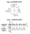
- FIG. 6 shows a detected rotating body 3 in the conventional rotating position detecting device described above.
- the detected rotating body 3 has four projections 3a ... in the periphery, and width ⁇ 0 of the projection 3a is detected to be used for control of an internal combustion engine.
- the lines (f) - (h) in FIG. 7 show change in magnetic flux density generated by rotation of the detected rotating body 3 of FIG. 6 and rectangular signals detected based on the change in magnetic flux density.
- the line (f) shows change in magnetic flux density A with time in the abscissa acting on the magneto-electric converter element.
- the magnetic flux density Aa shows a state of magnetic flux density generated in a case where a gap (hereinafter, referred to as "air gap”) between the top front of the rotating position detecting device (the magneto-electric converter element) and the detected rotating body 3 is narrow
- the magnetic flux density Ab shows a state of magnetic flux density generated in a case where the air gap is wide.
- the lines (g) and (h) in FIG. 7 show detected rectangular wave-forms B, C generated at the time when the generated magnetic flux densities Aa, Ab are at a threshold voltage V 1 '. It can be understood from the lines (f), (g) and (h) that the generated magnetic flux density Aa or Ab varies when the air gap varies, and the width (period) of the detected rectangular wave-form ⁇ 1 or ⁇ 2 becomes different shape when the threshold voltage V is kept constant. That is, it shows that the width of the detected signal wave-form ⁇ 1 or ⁇ 2 varies as the generated magnetic flux density Aa or Ab varies.
- Detecting the high level and the low level widths (time periods) ⁇ of the rectangular wave-form is equivalent to detecting the width of the projection or the groove of the detected rotating body.
- the difference in the gap between the top front of the rotating position detecting device (the magneto-electric converter element) and the detected rotating body that is, the variation of the air gap is not taken into consideration, and as a result there is a problem in that output signal of the rectangular wave-form is varied caused by the air gap and accordingly a crank angle (rotating position) cannot accurately be detected.
- the document EP-A-0 689 035 relates to an angular position detection apparatus for detecting an angular position of a rotating object, wherein two magnetoresistors are positioned adjacent to a target wheel attached to the rotating object, wherein the target wheel having at least one element of finite length.
- the magnetoresistors are generating analog signals with signal transitions between two voltage levels at the passage of the element's leading and trailing edges when the target wheel is rotated. Based on the analog signals a differential signal is formed, based on which the angular position of the target wheel is determined.
- An object of the present invention is to provide a rotating position detecting device capable of detecting a rotating position with high accuracy even if there exists variation in the air gap between the detected rotating body and the magneto-electric converter element (the rotating position detecting device) and capable of widening a permissible range of the gap variation.
- An internal combustion engine rotating position detecting device comprises a magneto-electric converter element for output an electric signal corresponding to a magnetic intensity, a magnet for generating a magnetic field, and the internal combustion engine rotating position detecting device is characterized in that a detected rotating body made of a magnetic material having irregularity and the position of the irregularity on the detected rotating body is converted into a rectangular wave-form electric signal, and a rotating position of the detected rotating body is detected based on a building-up signal or a falling signal of the rectangular wave-form. Further, the internal combustion engine rotating position detecting device is characterized by that a width between building-up positions or falling positions of two rectangular wave-forms is detected.
- the internal combustion engine rotating position detecting device is characterized by that the magneto-electric converter element is a differential type element having a plurality of magnetic-sensing portions, and the irregularity of the detected rotating body is formed by projections or grooves.
- the internal combustion engine rotating position detecting device is characterized by that number of that projections or the grooves arranged on the periphery of said detected rotating body is equal to an amount of necessary information, and the projections or the grooves are arranged in a unit of adjacent pair.
- the magnetic-sensing portion of the magneto-electric converter element and the projection or the groove of the detected rotating body repeat facing and not-facing by rotation of the detected rotating body, and magnetic field generated by the magnet is varied by the repeat of facing and not-facing, and magnetic flux density acting on the magneto-electric converter element is varied by the change of the magnetic field, and the change of the magnetic flux density is converted into a rectangular wave-form, and then a rotating position of the detected rotating body can be output as an electric signal by detecting building-up positions or falling positions of the two successive rectangular wave-forms.
- Generated magnetic flux density is varied by variation of the air gap based on a spacing between a position of the magnetic-sensing portion of the magneto-electric converter element and a position of the projection or the groove of the detected rotating body, and width (period) of the rectangular wave-form is varied by the variation of the generated magnetic flux density.
- a plurality of magnetic-sensing portions are provided in the magneto-electric converter elements and a plurality of magnetic flux densities detected by the plurality of magnetic-sensing portions are calculated to bring a building-up position or a falling position of the rectangular wave-form to nearly the same position even if there is difference in the air gaps. Thereby, it is possible to detect positions not affected by the effect of the air gap or being less affected by the effect of the air gap even if affected.
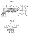
- FIG. 1 is a view showing the construction of an embodiment of a rotating position detecting device in accordance with the present invention.
- FIG. 2 is an enlarged schematic view of the detecting portion showing the magneto-electric converter element in the main body of rotation position detecting device and the detected rotating body in accordance with the present invention.
- FIG. 3 is a structural diagram showing the function of each part in the differential type magneto-electric converter element of FIG. 2.
- FIG. 4 is a chart showing the concept of operation of generated magnetic flux density and output wave-form of the rotating position detecting device of FIG. 2.
- FIGS. 5A, 5B, 5C are view showing other embodiments of detected rotating bodies of the rotating position detecting device of FIG. 1.
- FIG. 6 is a view showing a detected rotating body in a conventional rotating position detecting device.
- FIG. 7 is a chart showing the concept of operation of generated magnetic flux density and output wave-form of the conventional rotating position detecting device.
- FIG. 1 is a view showing the overall construction of an embodiment of a rotating position detecting device 10 in accordance with the present invention.
- the rotating position detecting device 10 is composed of a main body of rotating position detecting device 20 and a detected rotating body 13.
- the main body of rotating position detecting device 20 contains a magneto-electric converter element 11 for output an electric signal corresponding to a magnetic intensity and a magnet 12 for supplying magnetic field to the magneto-electric converter element 11 in a case 14, and comprises a terminal 16 for electrically connecting a circuit board 15 having electric power supplying function to the magneto-electric converter element 11 and input-output protecting function and the main body of rotating position detecting device 20 to the external and a metallic cover 17, made of a non-magnetic material such as stainless steel, for protecting the magneto-electric converter element 11.
- the detected rotating body 13 is rotated in synchronism with rotation of a crank shaft of an internal combustion engine.
- the detected rotating body 13 has projections arranged with a certain spacing, and number of the projections is equal to a number necessary for obtaining detected information, that is, eight projections 3a ... in this embodiment.
- the main body of rotating position detecting device 20 and the detected rotating body 13 are attached and fixed to the internal combustion engine with keeping an appropriate gap between them.
- the magneto-electric converter element 11 of the main body of rotating position detecting device 20 and the projection 13a repeat facing and not-facing.
- the repeat of facing and not-facing magnetic field generated by the magnet 12 is changed, and the change of the magnetic field causes change in magnetic flux density acting on the magneto-electric converter element 11. Therefore, a rotating position of the detected rotating body 13 can be obtained as an electric signal by the main body of rotating position detecting device 20, the electric signal is output from the terminal 16 through the circuit board 15.
- FIG. 2 is an enlarged schematic view of the detecting portion showing the magneto-electric converter element 11 of the main body of rotation position detecting device 20 and the detected rotating body 13, and shows the construction of a differential type magneto-electric converter element portion having at least two magnetic-sensing portions 11a, 11b.
- FIG. 3 is a structural diagram showing the functions of parts in the differential type magneto-electric converter element portion of FIG. 2.
- Magnetic-sensing portions 11a, 11b respectively detect voltage values caused by change of magnetic flux accompanied by rotation of the detected rotating body 13, and a comparator 11C calculates difference of the voltage values, and a Schmitt trigger circuit 11D wave-shapes the difference of the voltage values into a rectangular wave-form to output the external as a detected signal.
- FIG. 4 is a wave-form chart showing an operating state of the rotating position detecting device 10 of the present embodiment.
- the horizontal axis indicates elapsing time, and process of forming the rectangular wave-form of output signal is schematically shown starting from magnetic flux density based on the shape of the detected rotating body 13.
- FIG. 4 (a) shows the projections 13a, 13a of the detected rotating body 13 arranged with a certain spacing, and the projections 13a, 13a and the magnetic-sensing portions 11a, 11b repeat facing and not-facing by rotation of the detected rotating body 13.
- FIG. 4 (b) and (c) show applying states of magnetic fluxes (generated voltages after magneto-electric conversion) to the magnetic-sensing portions 11a, 11b of the magneto-electric converter element 11 based on the repeat of facing and not-facing, and the solid lines and the dotted lines show difference in the generated voltages caused by the air gap of positional spacing between the magnetic-sensing portions 11a, 11b of the magneto-electric converter element 11 and the projection 13a of the detected rotating body 13.
- the solid line shows a voltage wave-form in a case of a large air gap
- the dotted line shows a voltage wave-form in a case of a small air gap.
- FIG. 4 (d) shows a differential magnetic flux wave-form after the comparison calculation in the comparator 11C and threshold voltages V 1 , V 2 of the differential magnetic flux wave-form in the Schmitt trigger circuit 11D.
- the threshold voltage V 1 shows a threshold voltage for building-up wave-form V L-H and the threshold voltage V 2 shows a threshold voltage for falling wave-form V H-L .
- FIG. 4 (d)' is a differential magnetic flux obtained by subtracting the magnetic flux (c) of the magnetic-sensing portion 1b from the magnetic flux (b) of the magnetic-sensing portion 1a
- FIG. 4 (d)'' is a differential magnetic flux obtained by subtracting the magnetic flux (b) of the magnetic-sensing portion 1a from the magnetic flux (c) of the magnetic-sensing portion 1b.
- FIG. 4 (e) shows output signals of rectangular wave-form formed based on the threshold voltages V 1 , V 2 of the differential magnetic flux wave-form.
- FIG. 4 (e)' is a rectangular wave-form based on the differential magnetic flux (d)'
- FIG. 4 (e)'' is a rectangular wave-form based on the differential magnetic flux (d)''.
- the rectangular wave-form (e)' and the rectangular wave-form (e)'' are in reversed wave-form to each other. (However, by reversing the signals in output terminal using a transistor or the like, the both wave-forms are reversed.)
- an angle ⁇ 1 between the two building-up positions (in the case of the wave-form signal (e)' or between the two falling positions (in the case of the wave-form signal (e)" becomes equal to ⁇ 0 .
- FIGS. 5 (A) and (B) show other embodiments of detected rotating bodies 13 of which shapes are modified from that of FIG. 1.
- FIG. 5 (A) four pairs of adjacent projections 13a', 13a' are arranged on the periphery of the detected rotating body 13'.
- FIG. 5 (B) four pairs of adjacent grooves 13a'', 13a'' are arranged on the periphery of the detected rotating body 13".
- an output (i) of rectangular wave-form shown in FIG. 5 (C) can be obtained by rotating the detected rotating body 13' and forming a signal of rectangular wave-form as shown in FIG. 4.
- the output signal of rectangular wave-form a pair of adjacent rectangular wave-forms with an interval are output. Therefore, by calculating an interval angle ⁇ 1 between the falling edge portions of the pair of the rectangular wave-forms, the interval angle ⁇ 1 becomes equal to the angle ⁇ 0 between the falling portions of the pair of projections 13a', 13a'.
- the calculation of the interval angle ⁇ 1 between the falling edge portions of the pair of the rectangular wave-forms becomes practically equivalent to the calculation of the interval angle ⁇ 1 by generating and detecting a rectangular wave-form and detecting the building-up edge portion and the falling edge portion based on the width (spacing ⁇ 0 ) of one projection 3a of the conventional detected rotating body 3 as shown in FIG. 6 and FIG. 7.
- the angle ⁇ 0 between the pair of adjacent projections 13a', 13a' in the present embodiment is an angle mechanically determined, it is possible to detect the position with high accuracy by detecting the building-up portions of the pair of rectangular wave-forms detected and generated as described above even if there is variation in the gap between the magneto-electric converter element 11 and the detected rotating body 13, that is, the air gap since variation of position does not occur in the falling edge portion of the detected rectangular wave-form.
- the internal combustion engine rotating position detecting device in accordance with the present invention can accurately detect positions even if there is variation in amount of magnetic flux due to the air gap.
Landscapes
- Engineering & Computer Science (AREA)
- Physics & Mathematics (AREA)
- Electromagnetism (AREA)
- Chemical & Material Sciences (AREA)
- Combustion & Propulsion (AREA)
- Mechanical Engineering (AREA)
- General Engineering & Computer Science (AREA)
- Measurement Of Length, Angles, Or The Like Using Electric Or Magnetic Means (AREA)
- Combined Controls Of Internal Combustion Engines (AREA)
- Ignition Installations For Internal Combustion Engines (AREA)
- Transmission And Conversion Of Sensor Element Output (AREA)
Description
Claims (4)
- An internal combustion engine rotating position detecting device comprising a magneto-electric converter element (11) for outputting an electric signal corresponding to a magnetic intensity, a magnet (12) for generating a magnetic field, and a detected rotating body (13) made of a magnetic material having irregularity, wherein means are provided to convert a position of the irregularity on said detected rotating body (13) into a rectangular wave-form electric signal, and means are provided to detect a rotating position of the detected rotating body (13) based on a building-up signal or a falling signal of said rectangular wave-form, wherein said magneto-electric element (11) includes two magnetic-sensing portions (11a, 11b) which output signals based on a change of magnetic flux accompanied by rotation of the detected rotating body (13),
characterized in that, means are provided to detect said rotating position based on a difference of output signals of the two magnetic-sensing portions (11a, 11b) relating to the same building-up or falling signal caused by the same raising or falling edge of a respective irregularity (13a) of said detected rotating body (13). - An internal combustion engine rotating position detecting device according to claim 1, wherein detection of rotation position of said detected rotating body (13) is detection of a width between building-up positions or falling positions of two rectangular wave-forms.
- An internal combustion engine rotating position detecting device according to any one of claim 1 or 2, wherein said irregularity of the detected rotating body (13) is formed by projections (13a) or grooves.
- An internal combustion engine rotating position detecting device according to claim 3, wherein said projections (13a) or said grooves are arranged in a unit of adjacent pairs
Applications Claiming Priority (3)
| Application Number | Priority Date | Filing Date | Title |
|---|---|---|---|
| JP257123/96 | 1996-09-27 | ||
| JP25712396 | 1996-09-27 | ||
| JP25712396A JP3323082B2 (en) | 1996-09-27 | 1996-09-27 | Rotational position detecting device for internal combustion engine |
Publications (3)
| Publication Number | Publication Date |
|---|---|
| EP0833053A2 EP0833053A2 (en) | 1998-04-01 |
| EP0833053A3 EP0833053A3 (en) | 2000-07-12 |
| EP0833053B1 true EP0833053B1 (en) | 2005-11-16 |
Family
ID=17302057
Family Applications (1)
| Application Number | Title | Priority Date | Filing Date |
|---|---|---|---|
| EP97116087A Expired - Lifetime EP0833053B1 (en) | 1996-09-27 | 1997-09-16 | Internal combustion engine rotating position detecting device |
Country Status (4)
| Country | Link |
|---|---|
| US (1) | US6046584A (en) |
| EP (1) | EP0833053B1 (en) |
| JP (1) | JP3323082B2 (en) |
| DE (1) | DE69734635T2 (en) |
Families Citing this family (12)
| Publication number | Priority date | Publication date | Assignee | Title |
|---|---|---|---|---|
| US6291990B1 (en) * | 1997-09-29 | 2001-09-18 | Hitachi, Ltd. | Revolution sensor |
| US6640451B1 (en) * | 2000-01-28 | 2003-11-04 | Visteon Global Technologies, Inc. | System and method for sensing the angular position of a rotatable member |
| JP3615468B2 (en) * | 2000-07-06 | 2005-02-02 | ヒロセ電機株式会社 | Pulse signal generator |
| DE10116019B4 (en) * | 2001-03-30 | 2007-12-27 | Robert Bosch Gmbh | Sensor and method for its production |
| US7045997B2 (en) * | 2002-07-23 | 2006-05-16 | Mitsubishi Denki Kabushiki Kaisha | Magnetic detection apparatus |
| JP4292571B2 (en) * | 2003-03-31 | 2009-07-08 | 株式会社デンソー | Magnetic sensor adjustment method and magnetic sensor adjustment device |
| DE102005027362A1 (en) * | 2004-12-15 | 2006-06-22 | Robert Bosch Gmbh | Method for determining a switching point in the evaluation of the signals of a magnetic sensor arrangement |
| JP4543991B2 (en) * | 2005-03-25 | 2010-09-15 | トヨタ自動車株式会社 | Rotation angle detection device and internal combustion engine operation control device |
| JP4544003B2 (en) * | 2005-03-31 | 2010-09-15 | トヨタ自動車株式会社 | Rotation angle detection device and internal combustion engine operation control device |
| JP2006339757A (en) * | 2005-05-31 | 2006-12-14 | Denso Corp | Antenna coil, method for manufacturing communication board module, and card-type radio |
| JP4189683B2 (en) * | 2005-05-31 | 2008-12-03 | 株式会社デンソー | Antenna coil, method for manufacturing communication board module, and card-type radio |
| JP5055103B2 (en) * | 2007-12-14 | 2012-10-24 | 三菱重工業株式会社 | High position pump cam top position detector |
Family Cites Families (7)
| Publication number | Priority date | Publication date | Assignee | Title |
|---|---|---|---|---|
| DE3002947A1 (en) * | 1980-01-29 | 1981-07-30 | Robert Bosch Gmbh, 7000 Stuttgart | Measuring torque between drive and take=off shafts of vehicle - using relative position of shaft markers |
| JPH0672567B2 (en) * | 1988-03-18 | 1994-09-14 | 三菱電機株式会社 | Angle detector for internal combustion engine |
| DE3904958A1 (en) * | 1989-02-18 | 1990-08-23 | Dienes Apparatebau Gmbh | Position detector for machine parts |
| US5117681A (en) * | 1990-10-01 | 1992-06-02 | Ford Motor Company | Correction of systematic position-sensing errors in internal combustion engines |
| US5754042A (en) * | 1994-06-20 | 1998-05-19 | General Motors Corporation | Magnetoresistive encoder for tracking the angular position of a rotating ferromagnetic target wheel |
| JP3368681B2 (en) * | 1994-09-13 | 2003-01-20 | 株式会社デンソー | Magnetic detector |
| US5744950A (en) * | 1996-05-09 | 1998-04-28 | Ssi Technologies, Inc. | Apparatus for detecting the speed of a rotating element including signal conditioning to provide a fifty percent duty cycle |
-
1996
- 1996-09-27 JP JP25712396A patent/JP3323082B2/en not_active Expired - Lifetime
-
1997
- 1997-09-16 EP EP97116087A patent/EP0833053B1/en not_active Expired - Lifetime
- 1997-09-16 DE DE69734635T patent/DE69734635T2/en not_active Expired - Fee Related
- 1997-09-29 US US08/939,440 patent/US6046584A/en not_active Expired - Lifetime
Also Published As
| Publication number | Publication date |
|---|---|
| JP3323082B2 (en) | 2002-09-09 |
| DE69734635T2 (en) | 2006-07-27 |
| EP0833053A2 (en) | 1998-04-01 |
| JPH10103145A (en) | 1998-04-21 |
| US6046584A (en) | 2000-04-04 |
| EP0833053A3 (en) | 2000-07-12 |
| DE69734635D1 (en) | 2005-12-22 |
Similar Documents
| Publication | Publication Date | Title |
|---|---|---|
| US5574364A (en) | Position detector including a reference position wherein the sensor is saturating the MR sensor for preventing hysteresis and in a bridge circuit | |
| US4866381A (en) | Plural magnet device for magnetically detecting rotation angle of a rotary body | |
| US4551676A (en) | Pulse coder using magnetoresistance elements having an improved z-phase signal pattern | |
| EP0833053A2 (en) | Internal combustion engine rotating position detecting device | |
| US5869962A (en) | Magnetic detection apparatus for detecting movement of an object having a nonuniform system of teeth | |
| US5729127A (en) | Magnetism detecting apparatus having gear teeth dimensions for minimal pulse signal distortion | |
| EP0689035A1 (en) | Angular position detection apparatus | |
| US5115239A (en) | Magnetic absolute position encoder with an undulating track | |
| US4791366A (en) | Apparatus including a pair of angularly spaced sensors for detecting angle of rotation of a rotary member | |
| JPWO2009116365A1 (en) | Origin position signal detector | |
| US4713613A (en) | Device for magnetically detecting displacement of non-magnetic movable member | |
| JP3311429B2 (en) | Reference position detector | |
| US5172057A (en) | Magnetic encoder including plural magnetic pole lines having differing magnetic pitches and plural magnetic resistance effect elements | |
| JPH1019601A (en) | Magnetic detector | |
| JP2570510Y2 (en) | Optical encoder | |
| US11204260B2 (en) | System for determining at least one rotation parameter of a rotating member | |
| JPH11183498A (en) | Rotation detection device | |
| JP3182880B2 (en) | Rotation detection device | |
| EP0608810B1 (en) | Device for controlling printing position | |
| JPH10185621A (en) | Magnetic encoder device | |
| JPH02287210A (en) | Zero point detecting system for incremental type magnetic encoder | |
| JP3013140B2 (en) | Encoder | |
| JPS60114714A (en) | Magnetic encoder | |
| JPS6038615A (en) | Magnetic rotary encoder | |
| JPH0684893B2 (en) | Origin detection device for magnetic encoder |
Legal Events
| Date | Code | Title | Description |
|---|---|---|---|
| PUAI | Public reference made under article 153(3) epc to a published international application that has entered the european phase |
Free format text: ORIGINAL CODE: 0009012 |
|
| AK | Designated contracting states |
Kind code of ref document: A2 Designated state(s): DE FR GB IT |
|
| PUAL | Search report despatched |
Free format text: ORIGINAL CODE: 0009013 |
|
| AK | Designated contracting states |
Kind code of ref document: A3 Designated state(s): AT BE CH DE DK ES FI FR GB GR IE IT LI LU MC NL PT SE |
|
| 17P | Request for examination filed |
Effective date: 20001114 |
|
| AKX | Designation fees paid |
Free format text: DE FR GB IT |
|
| 17Q | First examination report despatched |
Effective date: 20031024 |
|
| GRAP | Despatch of communication of intention to grant a patent |
Free format text: ORIGINAL CODE: EPIDOSNIGR1 |
|
| GRAS | Grant fee paid |
Free format text: ORIGINAL CODE: EPIDOSNIGR3 |
|
| RAP1 | Party data changed (applicant data changed or rights of an application transferred) |
Owner name: HITACHI CAR ENGINEERING CO., LTD. Owner name: HITACHI, LTD. |
|
| GRAA | (expected) grant |
Free format text: ORIGINAL CODE: 0009210 |
|
| AK | Designated contracting states |
Kind code of ref document: B1 Designated state(s): DE FR GB IT |
|
| PG25 | Lapsed in a contracting state [announced via postgrant information from national office to epo] |
Ref country code: IT Free format text: LAPSE BECAUSE OF FAILURE TO SUBMIT A TRANSLATION OF THE DESCRIPTION OR TO PAY THE FEE WITHIN THE PRESCRIBED TIME-LIMIT;WARNING: LAPSES OF ITALIAN PATENTS WITH EFFECTIVE DATE BEFORE 2007 MAY HAVE OCCURRED AT ANY TIME BEFORE 2007. THE CORRECT EFFECTIVE DATE MAY BE DIFFERENT FROM THE ONE RECORDED. Effective date: 20051116 |
|
| REG | Reference to a national code |
Ref country code: GB Ref legal event code: FG4D |
|
| REF | Corresponds to: |
Ref document number: 69734635 Country of ref document: DE Date of ref document: 20051222 Kind code of ref document: P |
|
| ET | Fr: translation filed | ||
| PLBE | No opposition filed within time limit |
Free format text: ORIGINAL CODE: 0009261 |
|
| STAA | Information on the status of an ep patent application or granted ep patent |
Free format text: STATUS: NO OPPOSITION FILED WITHIN TIME LIMIT |
|
| 26N | No opposition filed |
Effective date: 20060817 |
|
| GBPC | Gb: european patent ceased through non-payment of renewal fee |
Effective date: 20060916 |
|
| PG25 | Lapsed in a contracting state [announced via postgrant information from national office to epo] |
Ref country code: GB Free format text: LAPSE BECAUSE OF NON-PAYMENT OF DUE FEES Effective date: 20060916 |
|
| PGFP | Annual fee paid to national office [announced via postgrant information from national office to epo] |
Ref country code: FR Payment date: 20080814 Year of fee payment: 12 |
|
| PGFP | Annual fee paid to national office [announced via postgrant information from national office to epo] |
Ref country code: DE Payment date: 20080908 Year of fee payment: 12 |
|
| REG | Reference to a national code |
Ref country code: FR Ref legal event code: ST Effective date: 20100531 |
|
| PG25 | Lapsed in a contracting state [announced via postgrant information from national office to epo] |
Ref country code: FR Free format text: LAPSE BECAUSE OF NON-PAYMENT OF DUE FEES Effective date: 20090930 Ref country code: DE Free format text: LAPSE BECAUSE OF NON-PAYMENT OF DUE FEES Effective date: 20100401 |