EP0832496B1 - Switching equipment - Google Patents
Switching equipment Download PDFInfo
- Publication number
- EP0832496B1 EP0832496B1 EP96917798A EP96917798A EP0832496B1 EP 0832496 B1 EP0832496 B1 EP 0832496B1 EP 96917798 A EP96917798 A EP 96917798A EP 96917798 A EP96917798 A EP 96917798A EP 0832496 B1 EP0832496 B1 EP 0832496B1
- Authority
- EP
- European Patent Office
- Prior art keywords
- contactor
- coil
- switching equipment
- detection means
- equipment according
- Prior art date
- Legal status (The legal status is an assumption and is not a legal conclusion. Google has not performed a legal analysis and makes no representation as to the accuracy of the status listed.)
- Expired - Lifetime
Links
Images



Classifications
-
- H—ELECTRICITY
- H01—ELECTRIC ELEMENTS
- H01H—ELECTRIC SWITCHES; RELAYS; SELECTORS; EMERGENCY PROTECTIVE DEVICES
- H01H47/00—Circuit arrangements not adapted to a particular application of the relay and designed to obtain desired operating characteristics or to provide energising current
- H01H47/002—Monitoring or fail-safe circuits
- H01H47/004—Monitoring or fail-safe circuits using plural redundant serial connected relay operated contacts in controlled circuit
-
- H—ELECTRICITY
- H01—ELECTRIC ELEMENTS
- H01H—ELECTRIC SWITCHES; RELAYS; SELECTORS; EMERGENCY PROTECTIVE DEVICES
- H01H89/00—Combinations of two or more different basic types of electric switches, relays, selectors and emergency protective devices, not covered by any single one of the other main groups of this subclass
- H01H89/06—Combination of a manual reset circuit with a contactor, i.e. the same circuit controlled by both a protective and a remote control device
- H01H2089/065—Coordination between protection and remote control, e.g. protection job repartition, mutual assistance or monitoring
-
- H—ELECTRICITY
- H01—ELECTRIC ELEMENTS
- H01H—ELECTRIC SWITCHES; RELAYS; SELECTORS; EMERGENCY PROTECTIVE DEVICES
- H01H3/00—Mechanisms for operating contacts
- H01H3/001—Means for preventing or breaking contact-welding
-
- H—ELECTRICITY
- H01—ELECTRIC ELEMENTS
- H01H—ELECTRIC SWITCHES; RELAYS; SELECTORS; EMERGENCY PROTECTIVE DEVICES
- H01H47/00—Circuit arrangements not adapted to a particular application of the relay and designed to obtain desired operating characteristics or to provide energising current
- H01H47/22—Circuit arrangements not adapted to a particular application of the relay and designed to obtain desired operating characteristics or to provide energising current for supplying energising current for relay coil
- H01H47/32—Energising current supplied by semiconductor device
- H01H47/325—Energising current supplied by semiconductor device by switching regulator
-
- H—ELECTRICITY
- H01—ELECTRIC ELEMENTS
- H01H—ELECTRIC SWITCHES; RELAYS; SELECTORS; EMERGENCY PROTECTIVE DEVICES
- H01H89/00—Combinations of two or more different basic types of electric switches, relays, selectors and emergency protective devices, not covered by any single one of the other main groups of this subclass
- H01H89/06—Combination of a manual reset circuit with a contactor, i.e. the same circuit controlled by both a protective and a remote control device
Definitions
- the invention relates to switching equipment with an electromagnetic contactor and a circuit breaker which is located ahead of the contactor.
- the contactor has an operating magnetic circuit with a magnetic core, an operating coil and an armature which moves in dependence on the current through the operating coil. Further, the contactor has a number of contacts which are influenced by the armature.
- Electromagnetic contactors are known and have been used for a long time, for example as switching means between a voltage source and an electric motor.
- One problem with such contactors is that one or a few of the contact pairs of a contactor may become fixed to each other by welding, and the risk of this is greater at high currents.
- Such welding together of contact pairs may, for example, be caused by contact bouncing when closing the contactor towards a high making current of an electric motor.
- European patent application EP 558 190 A1 discloses an electromagnetic contactor with a closure fault indicator.
- a drive circuit upon receipt of a signal, a drive circuit applies the full power of the power supply to a contactor coil. This causes the closure of the power contacts of the contactor. A pulsing mode is thereafter applied to hold the contacts in place.
- the purpose of this known device is to verify that the contacts have actually been closed on receipt of the signal.
- the contactor includes a sensing circuit, determining if the contacts are closed, by sensing the reluctance of the contactor coil. The current through the coil is used to determine the reluctance of the contactor coil. When an opening order is sent to the contactor, the coil is disconnected from the power supply. This results in the current through the coil decreasing towards zero.
- the object of the invention is to provide switching equipment of the kind mentioned in the introductory part of the description, in which the risk of damage and other inconvenience, which may otherwise arise during an incomplete opening of the contactor caused by welded-together contacts, is eliminated in a simple manner.
- Figure 1 shows switching equipment according to the invention, connected in the supply conduit of an ac motor.
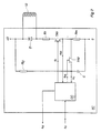
- Figure 2 shows the composition of the control equipment of the contactor.
- Figure 3 shows the control circuit included in the control equipment.
- Figure 4 shows how some of the quantities occurring in the switching equipment vary with time during an opening operation.
- FIG. 1 shows switching equipment according to the invention connected to the line between a three-phase motor M and an alternating-voltage power supply network N.
- the switching equipment comprises contactor equipment CE and a circuit breaker BR located ahead of the contact equipment (by “ahead of” is meant that the circuit breaker is arranged between the contactor equipment and the supply network.)
- the function of the switching equipment is to connect, in dependence on a control signal s c , the motor to or disconnect the motor from the supply voltage.
- the control signal may be obtained in a known manner from superordinate control equipment or be supplied manually.
- the contactor equipment is usually adapted also to serve as thermal overload protection means for the motor and then receives an opening signal from a current-sensing protective circuit (not shown).
- the circuit breaker BR which in a known way is adapted to trip at overcurrents, serves as overcurrent protection device. As shown in the figure, the circuit breaker also receives a tripping signal sd from the contactor equipment for opening of the circuit breaker if contacts of the contactor have become fixed by welding.
- the contactor equipment has a bank of contacts 10 which, in the three-phase application shown, has three contacts, one for each phase. Via a resilient mechanical link 14, the contacts are mechanically connected to the armature 13 of the operating magnet 11 of the contactor, which magnet has an operating coil 12.
- the contactor equipment has control equipment SC which receives the control signal s c . Upon orders for closing, the control equipment feeds a current I to the operating coil and maintains this current at a desired value.
- the control circuit comprises circuits for detecting contacts which have become fixed by welding and for supply of a detection signal sd for tripping of the circuit breaker BR if it is detected that contacts have become fixed by welding.
- FIG. 2 shows the composition of the control equipment SC.
- the operating coil 12 is connected, in series with a resistor R1, a switching transistor TR1 and a measuring resistor Rm, to a supply voltage source with a direct voltage +U.
- a bypass diode D is connected in parallel with the operating coil.
- a measuring voltage u m corresponding to the current I through the coil (in case of a non-conducting diode D), is obtained across the measuring resistor.
- the transistor TR1 is used, in the manner which will be described below, for control of the current through the coil 12 upon closing of the contactor and in the closed position, as well as for applying a voltage pulse to the coil for detection of contacts being fixed by welding.
- An RC circuit comprising a resistor R C and a capacitor C is connected to the supply voltage source.
- the capacitor may be connected to the measuring resistor with the aid of a switching transistor TR2.
- a control circuit CC receives the control signal s c and the measurement signals u m and u c - the latter corresponding to the capacitor voltage - and delivers control signals s I and s rs to the transistors TR1 and TR2 and the tripping signal s d to the circuit breaker BR.
- FIG. 3 shows the composition of the control circuit CC.
- the measurement signal u m is supplied to an input of a level-sensing circuit NV1, and to the second, inverting input there is supplied a reference value I 0 which corresponds to the desired current through the operating coil 12 when the contactor is closed.
- the circuit NV1 has a certain hysteresis and delivers an output signal which becomes "0" if the coil current rises above an upper limit value and which becomes “1” if the current drops below a lower limit.
- the AND circuit releases the signal from NV1 and hence the control signals to the transistor if there is an order for a closed contactor, that is, if the control signal s c is "1".
- the circuit described so far thus controls, in a manner known per se, by pulsing the transistor TR1, the current through the operating coil to the desired value independently of supply voltages varying within wide limits. Circuits of this kind for control of the current through the operating coil of a contactor are known per se, for example from the published patent applications EP 0 136 968 A3 and WO 86/01332.
- the control signal s c is also supplied to a monostable circuit MV1 which is triggered when the control signal changes from "1" to "0", that is, when an opening order is given to the contactor.
- the circuit MV1 then delivers a pulse with a duration t 1 so adjusted that the contactor has normally had time to assume the open position at the end of the pulse.
- the output signal from the circuit MV1 is supplied to two additional monostable circuits MV2 and MV3, which are both triggered at the end of the pulse from MV1, that is, the time t 1 after an opening order to the contactor.
- the circuit MV2 delivers a short control pulse s rs to the transistor TR2, which thereby becomes conducting for a short moment and causes the capacitor voltage u c to become identical with the voltage u m across the measuring resistor.
- the circuit MV3 delivers a pulse with the duration t 2 which corresponds to the length of the detection interval and which, for example, may be 0.1 ms. This pulse is supplied to the transistor TR1 via the OR circuit EG and controls the transistor to a conducting state for the duration of the pulse. In this way, the supply voltage U is continuously applied to the operating coil 12 for the duration of the detection pulse.
- the pulse from the circuit MV3 is also supplied to a fourth monostable circuit MV4, which is triggered at the end of the pulse from MV3, that is, at the end of the detection interval, and then delivers a short signal to a second AND circuit OG2.
- a level-sensing circuit NV2 is supplied with the signals uc and u m , the latter with reversed sign. If u c > u m , the output signal of the circuit is "1", and when, at the end of the detection interval, the circuit OG2 receives a pulse from the circuit MV4, a signal s d is delivered which indicates whether any of the contacts of the contactor has been fixed by welding. This signal is supplied to the circuit breaker BR and triggers an immediate opening of the circuit breaker.
- Figure 4 illustrates the process of some of the quantities occurring in the switching equipment.
- the control equipment controls the current I through the operating coil by pulsing the transistor TR1, the control signal s I of which is shown below the control signal s c in the figure. Below this, the current I is shown and as is clear from the diagram this is controlled such that its mean value corresponds to the reference value I 0 .
- the detection interval is started.
- a short control pulse s rs is supplied to the transistor TR2, which becomes conducting and causes the capacitor voltage u c to become identical with the measuring voltage u m .
- the transistor TR1 is controlled to the conducting state and the supply voltage U is applied to the operating coil. Its current I then increases at a rate which is dependent on the magnitude of the supply voltage and on the inductance of the operating coil (the coil resistance is assumed to be constant).
- the inductance in its turn, is dependent on the reluctance (the magnetic resistance) of the magnetic circuit of the operating magnet. The reluctance varies, in turn, with the air gap between the armature and the magnetic core.
- the two lowermost diagrams in Figure 4 show how the current I and the measurement signal um vary during the detection interval.
- the normal process is shown in dotted lines.
- the air gap has had time to assume its greatest value even at the beginning of the detection interval, the reluctance is great and the coil inductance small, and therefore the coil current increases rapidly.
- the unbroken lines show the process if at least one contact is fixed by welding. The reluctance then becomes lower and the coil inductance greater, and the current increases more slowly.
- the time constant of the RC circuit RC-C is so chosen that the signal uc increases more slowly than the coil current in the normal case but faster than the coil current in case of a contact which is fixed by welding.
- the important advantage is obtained that variations in the supply voltage will influence the rate of growth of the comparison quantity u c in the same way and to the same extent as the variations influence the rate of growth of the coil current.
- the detection of contacts fixed by welding therefore becomes correct even if the supply voltage varies, and switching equipment according to the invention may be connected to different supply voltages without influencing the detection.
- the detection becomes correct independently of the magnitude of the coil current at the beginning of the interval. This is an important advantage and makes it possible, for example, without negatively influencing the accuracy of the detection, to initiate the detection, and when necessary achieve disconnection of the contactor, earlier than what would otherwise have been possible, thus reducing the harmful effects of contacts being fixed by welding.
- the reluctance in the open position is about 3-10 times greater than in the closed position, that is, the coil inductance is about 3-10 times lower.
- This relatively large ratio makes possible a reliable detection of contacts being fixed by welding by utilizing a reluctance determination.
- the method described above is simple and economically advantageous. It requires no transducers or extra connections of the contactor and only a relatively simple supplementation of the static parts of the contactor equipment. In the case described above, where the invention is applied to contactor equipment which is provided with means for control of the current of the operating coil, the already existing control means are utilized, and the only thing that is required is a moderate supplementation of the signal-processing circuits of the equipment.
- the change in the reluctance of the operating magnet, in dependence on the position of the armature, is utilized for the detection.
- Quantities equivalent to the reluctance may, of course, alternatively be used within the scope of the invention, for example the inverted value of the reluctance, the permeance, or the coil inductance proportional to the permeance.
- the operating coil and its current-controlling means have been used for the reluctance determination, which is a simple and advantageous embodiment, but alternatively there may be used, for example, a separate inductance measuring coil.
- a measure of the reluctance is formed by determining the current change during a time interval of a predetermined length.
- a measure of the reluctance may be formed by determining the time for a predetermined current change.
- the resetting of the comparison quantity (by closing the transistor TR2) described above causes the measurement to be completely independent of which value the current coil has at the beginning of the detection interval.
- the invention has been described above with reference to a contactor, the contacts of which are open when the contactor is in the open position and closed in the closed position.
- the invention can also be applied to a contactor with at least some contact which is closed in the open position of the contactor and where thus the contactor, when this contact has been fixed by welding, may stop in an intermediate position when closing the contactor.
- control and detection equipment is a mixture of analog and digital circuits, but, of course, the corresponding functions may be obtained in other ways, for example with the aid of an appropriately programmed microprocessor.
Landscapes
- Relay Circuits (AREA)
- Testing Of Short-Circuits, Discontinuities, Leakage, Or Incorrect Line Connections (AREA)
Abstract
Description
- The invention relates to switching equipment with an electromagnetic contactor and a circuit breaker which is located ahead of the contactor. The contactor has an operating magnetic circuit with a magnetic core, an operating coil and an armature which moves in dependence on the current through the operating coil. Further, the contactor has a number of contacts which are influenced by the armature.
- Electromagnetic contactors are known and have been used for a long time, for example as switching means between a voltage source and an electric motor. One problem with such contactors is that one or a few of the contact pairs of a contactor may become fixed to each other by welding, and the risk of this is greater at high currents. Such welding together of contact pairs may, for example, be caused by contact bouncing when closing the contactor towards a high making current of an electric motor.
- The fact that one or more contact pairs become fixed by welding may entail serious harmful effects. Upon an opening order to a contactor with a welded-together contact pair, the armature will move a certain distance in the opening direction, because of the resilience in the mechanical coupling, and then stop in an intermediate position. This may cause arcs in the contact pairs which are not welded together, and fire, explosion or other damage to the contactor and other equipment. In many applications, it may also, and independently thereof, entail serious consequences that a contactor does not open when, according to a supplied opening signal, it should have opened.
- European patent application EP 558 190 A1 discloses an electromagnetic contactor with a closure fault indicator. According to the above-mentioned application, upon receipt of a signal, a drive circuit applies the full power of the power supply to a contactor coil. This causes the closure of the power contacts of the contactor. A pulsing mode is thereafter applied to hold the contacts in place. The purpose of this known device is to verify that the contacts have actually been closed on receipt of the signal. The contactor includes a sensing circuit, determining if the contacts are closed, by sensing the reluctance of the contactor coil. The current through the coil is used to determine the reluctance of the contactor coil. When an opening order is sent to the contactor, the coil is disconnected from the power supply. This results in the current through the coil decreasing towards zero.
- The object of the invention is to provide switching equipment of the kind mentioned in the introductory part of the description, in which the risk of damage and other inconvenience, which may otherwise arise during an incomplete opening of the contactor caused by welded-together contacts, is eliminated in a simple manner.
- What characterizes switching equipment according to the invention will become clear from the appended claims.
- The invention will be explained in greater detail in the following with reference to the accompanying Figures 1-4. Figure 1 shows switching equipment according to the invention, connected in the supply conduit of an ac motor. Figure 2 shows the composition of the control equipment of the contactor. Figure 3 shows the control circuit included in the control equipment. Figure 4 shows how some of the quantities occurring in the switching equipment vary with time during an opening operation.
- Figure 1 shows switching equipment according to the invention connected to the line between a three-phase motor M and an alternating-voltage power supply network N. The switching equipment comprises contactor equipment CE and a circuit breaker BR located ahead of the contact equipment (by "ahead of" is meant that the circuit breaker is arranged between the contactor equipment and the supply network.) The function of the switching equipment is to connect, in dependence on a control signal sc, the motor to or disconnect the motor from the supply voltage. The control signal may be obtained in a known manner from superordinate control equipment or be supplied manually. The contactor equipment is usually adapted also to serve as thermal overload protection means for the motor and then receives an opening signal from a current-sensing protective circuit (not shown). The circuit breaker BR, which in a known way is adapted to trip at overcurrents, serves as overcurrent protection device. As shown in the figure, the circuit breaker also receives a tripping signal sd from the contactor equipment for opening of the circuit breaker if contacts of the contactor have become fixed by welding.
- In the usual manner, the contactor equipment has a bank of
contacts 10 which, in the three-phase application shown, has three contacts, one for each phase. Via a resilientmechanical link 14, the contacts are mechanically connected to thearmature 13 of theoperating magnet 11 of the contactor, which magnet has anoperating coil 12. The contactor equipment has control equipment SC which receives the control signal sc. Upon orders for closing, the control equipment feeds a current I to the operating coil and maintains this current at a desired value. Further, the control circuit comprises circuits for detecting contacts which have become fixed by welding and for supply of a detection signal sd for tripping of the circuit breaker BR if it is detected that contacts have become fixed by welding. - Figure 2 shows the composition of the control equipment SC. The
operating coil 12 is connected, in series with a resistor R1, a switching transistor TR1 and a measuring resistor Rm, to a supply voltage source with a direct voltage +U. A bypass diode D is connected in parallel with the operating coil. A measuring voltage um, corresponding to the current I through the coil (in case of a non-conducting diode D), is obtained across the measuring resistor. The transistor TR1 is used, in the manner which will be described below, for control of the current through thecoil 12 upon closing of the contactor and in the closed position, as well as for applying a voltage pulse to the coil for detection of contacts being fixed by welding. An RC circuit comprising a resistor RC and a capacitor C is connected to the supply voltage source. The capacitor may be connected to the measuring resistor with the aid of a switching transistor TR2. A control circuit CC receives the control signal sc and the measurement signals um and uc - the latter corresponding to the capacitor voltage - and delivers control signals sI and srs to the transistors TR1 and TR2 and the tripping signal sd to the circuit breaker BR. - Figure 3 shows the composition of the control circuit CC. The measurement signal um is supplied to an input of a level-sensing circuit NV1, and to the second, inverting input there is supplied a reference value I0 which corresponds to the desired current through the
operating coil 12 when the contactor is closed. The circuit NV1 has a certain hysteresis and delivers an output signal which becomes "0" if the coil current rises above an upper limit value and which becomes "1" if the current drops below a lower limit. The output signal of the circuit is forwarded via an AND circuit OG1 to an OR circuit EG, the output signal sI of which controls the transistor TR1, which is on at sI = 1 and off if sI = 0. The AND circuit releases the signal from NV1 and hence the control signals to the transistor if there is an order for a closed contactor, that is, if the control signal sc is "1". The circuit described so far thus controls, in a manner known per se, by pulsing the transistor TR1, the current through the operating coil to the desired value independently of supply voltages varying within wide limits. Circuits of this kind for control of the current through the operating coil of a contactor are known per se, for example from the publishedpatent applications EP 0 136 968 A3 and WO 86/01332. - The control signal sc is also supplied to a monostable circuit MV1 which is triggered when the control signal changes from "1" to "0", that is, when an opening order is given to the contactor. The circuit MV1 then delivers a pulse with a duration t1 so adjusted that the contactor has normally had time to assume the open position at the end of the pulse. The output signal from the circuit MV1 is supplied to two additional monostable circuits MV2 and MV3, which are both triggered at the end of the pulse from MV1, that is, the time t1 after an opening order to the contactor. The circuit MV2 delivers a short control pulse srs to the transistor TR2, which thereby becomes conducting for a short moment and causes the capacitor voltage uc to become identical with the voltage um across the measuring resistor. The circuit MV3 delivers a pulse with the duration t2 which corresponds to the length of the detection interval and which, for example, may be 0.1 ms. This pulse is supplied to the transistor TR1 via the OR circuit EG and controls the transistor to a conducting state for the duration of the pulse. In this way, the supply voltage U is continuously applied to the
operating coil 12 for the duration of the detection pulse. The pulse from the circuit MV3 is also supplied to a fourth monostable circuit MV4, which is triggered at the end of the pulse from MV3, that is, at the end of the detection interval, and then delivers a short signal to a second AND circuit OG2. - A level-sensing circuit NV2 is supplied with the signals uc and um, the latter with reversed sign. If uc > um, the output signal of the circuit is "1", and when, at the end of the detection interval, the circuit OG2 receives a pulse from the circuit MV4, a signal sd is delivered which indicates whether any of the contacts of the contactor has been fixed by welding. This signal is supplied to the circuit breaker BR and triggers an immediate opening of the circuit breaker.
- Figure 4 illustrates the process of some of the quantities occurring in the switching equipment. At the top in the figure, the control signal sc is shown, which is "1" up to t= t0, that is, for t ≤ t0 the contactor is in the closed position. The control equipment controls the current I through the operating coil by pulsing the transistor TR1, the control signal sI of which is shown below the control signal sc in the figure. Below this, the current I is shown and as is clear from the diagram this is controlled such that its mean value corresponds to the reference value I0.
- At t = t0 an opening order is given, and the control signal sc becomes "0". The coil current I then decreases exponentially towards zero.
- After the time t1 determined by the circuit MV1, the detection interval is started. A short control pulse srs is supplied to the transistor TR2, which becomes conducting and causes the capacitor voltage uc to become identical with the measuring voltage um. At the same time, the transistor TR1 is controlled to the conducting state and the supply voltage U is applied to the operating coil. Its current I then increases at a rate which is dependent on the magnitude of the supply voltage and on the inductance of the operating coil (the coil resistance is assumed to be constant). The inductance, in its turn, is dependent on the reluctance (the magnetic resistance) of the magnetic circuit of the operating magnet. The reluctance varies, in turn, with the air gap between the armature and the magnetic core. It is smallest in fully closed position, when the air gap is zero, and greatest in fully opened position when the air gap has its greatest value. If one or more of the contacts of the contactor should be fixed by welding upon an opening operation, the armature, because of the resilient mechanical coupling between the armature and the contacts, will move a certain distance until the welded contact or contacts prevent continued movement. The armature then stops in an intermediate position, where the reluctance assumes a value between its greatest and its smallest value.
- The two lowermost diagrams in Figure 4 show how the current I and the measurement signal um vary during the detection interval. The normal process is shown in dotted lines. The air gap has had time to assume its greatest value even at the beginning of the detection interval, the reluctance is great and the coil inductance small, and therefore the coil current increases rapidly. The unbroken lines show the process if at least one contact is fixed by welding. The reluctance then becomes lower and the coil inductance greater, and the current increases more slowly. The time constant of the RC circuit RC-C is so chosen that the signal uc increases more slowly than the coil current in the normal case but faster than the coil current in case of a contact which is fixed by welding. At the end of the detection interval, therefore, in the normal case um > uc and no output signal is obtained from the circuit NV2. In the case of a welded contact, on the other hand, at the end of the interval um < uc, the output signal from the circuit NV2 becomes "1" and a tripping signal sd is delivered to the circuit breaker BR. This causes the circuit breaker to immediately trip and prevent further damage to the contactor and damage to the other equipment.
- By supplying the RC circuit in the above-described embodiment from the same supply voltage source as the operating coil, the important advantage is obtained that variations in the supply voltage will influence the rate of growth of the comparison quantity uc in the same way and to the same extent as the variations influence the rate of growth of the coil current. The detection of contacts fixed by welding therefore becomes correct even if the supply voltage varies, and switching equipment according to the invention may be connected to different supply voltages without influencing the detection.
- By setting the comparison quantity uc, at the beginning of the detection interval, always equal to the value which corresponds to the coil current, the detection becomes correct independently of the magnitude of the coil current at the beginning of the interval. This is an important advantage and makes it possible, for example, without negatively influencing the accuracy of the detection, to initiate the detection, and when necessary achieve disconnection of the contactor, earlier than what would otherwise have been possible, thus reducing the harmful effects of contacts being fixed by welding.
- From experience, in a typical contactor, the reluctance in the open position is about 3-10 times greater than in the closed position, that is, the coil inductance is about 3-10 times lower. This relatively large ratio makes possible a reliable detection of contacts being fixed by welding by utilizing a reluctance determination. Further, the method described above is simple and economically advantageous. It requires no transducers or extra connections of the contactor and only a relatively simple supplementation of the static parts of the contactor equipment. In the case described above, where the invention is applied to contactor equipment which is provided with means for control of the current of the operating coil, the already existing control means are utilized, and the only thing that is required is a moderate supplementation of the signal-processing circuits of the equipment.
- The equipment described above is only an example, and switching equipment according to the invention can be designed in a plurality of other ways than that described above.
- According to the invention, the change in the reluctance of the operating magnet, in dependence on the position of the armature, is utilized for the detection. Quantities equivalent to the reluctance may, of course, alternatively be used within the scope of the invention, for example the inverted value of the reluctance, the permeance, or the coil inductance proportional to the permeance.
- In the above description, the operating coil and its current-controlling means have been used for the reluctance determination, which is a simple and advantageous embodiment, but alternatively there may be used, for example, a separate inductance measuring coil.
- In the embodiment described above, a measure of the reluctance is formed by determining the current change during a time interval of a predetermined length. Alternatively, of course, a measure of the reluctance may be formed by determining the time for a predetermined current change.
- The resetting of the comparison quantity (by closing the transistor TR2) described above causes the measurement to be completely independent of which value the current coil has at the beginning of the detection interval.
- The invention has been described above with reference to a contactor, the contacts of which are open when the contactor is in the open position and closed in the closed position. The invention can also be applied to a contactor with at least some contact which is closed in the open position of the contactor and where thus the contactor, when this contact has been fixed by welding, may stop in an intermediate position when closing the contactor.
- In the embodiment described above, the control and detection equipment is a mixture of analog and digital circuits, but, of course, the corresponding functions may be obtained in other ways, for example with the aid of an appropriately programmed microprocessor.
Claims (9)
- Switching equipment with an electromagnetic contactor (CE) and a circuit breaker (BR) located ahead of the contactor, wherein the contactor has an operating magnetic circuit with a magnetic core (11), an operating coil (12) and an armature (13) which moves in dependence on the current (I) through the operating coil, as well as a number of contacts (10) which are influenced by the armature, the switching equipment comprises detection means (SC, CC) adapted to sense the reluctance of the operating magnetic circuit, characterized in that the detection means (SC, CC), in dependence on the measured reluctance, are adapted to generate a signal (Sd) which indicates an incomplete opening of the contactor caused by welded-together contacts, said signal being adapted to be supplied to the circuit breaker in such a way that, upon detection of welded-together contacts, the contactor is disconnected by opening of the circuit breaker.
- Switching equipment according to claim 1, characterized in that the detection means are adapted to form a measure of the reluctance of the operating magnetic circuit by sensing the inductance of an inductance measuring coil (12) surrounding the magnetic core (11).
- Switching equipment according to claim 2, characterized in that the inductance measuring coil consists of the operating coil (12).
- Switching equipment according to any of claims 2 and 3, characterized in that the detection means are adapted to apply to the inductance measuring coil (12) a voltage pulse (U, t2) and to detect the inductance of the coil on the basis of the current response (um) of the coil.
- Switching equipment according to claim 4, characterized in that the detection means are adapted, at a predetermined time (t2) after the start of the voltage pulse, to compare the current response (um) with a reference level (uc)
- Switching equipment according to claim 4, characterized in that the detection means are adapted, when reaching a predetermined current level, to compare the time interval since the start of the voltage pulse with a predetermined time interval.
- Switching equipment according to any of claims 3-6, in which the operating coil (12) is connected to a voltage source (+U) in series with a switching member (TR1) for controlling the current (I) through the coil, characterized in that the detection means comprise means (MV3, EG) adapted to control the switching means into a conducting state for applying said voltage pulse across the operating coil.
- Switching equipment according to claim 5, characterized in that the detection means are adapted to apply said voltage pulse to the inductance measuring coil (12) by connecting the coil to a voltage source (+U) and that the detection means comprise means (R, C) adapted to form the reference level (uc) in dependence on the voltage of the voltage source for reduction of the dependence of the detection on said voltage.
- Switching equipment according to any of the preceding claims, characterized in that the detection means are adapted to carry out the sensing of the reluctance of the operating magnetic circuit when a time interval (t1) has elapsed after an opening order received by the contactor.
Applications Claiming Priority (3)
| Application Number | Priority Date | Filing Date | Title |
|---|---|---|---|
| SE9502123 | 1995-06-12 | ||
| SE9502123A SE515261C2 (en) | 1995-06-12 | 1995-06-12 | Contactor |
| PCT/SE1996/000762 WO1996042098A1 (en) | 1995-06-12 | 1996-06-12 | Switching equipment |
Publications (2)
| Publication Number | Publication Date |
|---|---|
| EP0832496A1 EP0832496A1 (en) | 1998-04-01 |
| EP0832496B1 true EP0832496B1 (en) | 2001-05-23 |
Family
ID=20398580
Family Applications (1)
| Application Number | Title | Priority Date | Filing Date |
|---|---|---|---|
| EP96917798A Expired - Lifetime EP0832496B1 (en) | 1995-06-12 | 1996-06-12 | Switching equipment |
Country Status (5)
| Country | Link |
|---|---|
| US (1) | US6023110A (en) |
| EP (1) | EP0832496B1 (en) |
| DE (1) | DE69612975T2 (en) |
| SE (1) | SE515261C2 (en) |
| WO (1) | WO1996042098A1 (en) |
Cited By (6)
| Publication number | Priority date | Publication date | Assignee | Title |
|---|---|---|---|---|
| WO2006069970A1 (en) * | 2004-12-23 | 2006-07-06 | Siemens Aktiengesellschaft | Method and device for the safe operation of a switching device |
| WO2006069958A1 (en) * | 2004-12-23 | 2006-07-06 | Siemens Aktiengesellschaft | Method and device for securely operating a switching device |
| WO2006069960A1 (en) * | 2004-12-23 | 2006-07-06 | Siemens Aktiengesellschaft | Method and device for the secure operation of a switching device |
| WO2006069963A1 (en) * | 2004-12-23 | 2006-07-06 | Siemens Aktiengesellschaft | Method and device for the secure operation of a switching device |
| US7978036B2 (en) | 2004-12-23 | 2011-07-12 | Siemens Aktiengesellschaft | Method and device for the secure operation of a switching device |
| EP2983187A3 (en) * | 2014-08-05 | 2016-05-25 | Tyco Electronics (Shanghai) Co. Ltd. | Contactor, contactor assembly and control circuit |
Families Citing this family (29)
| Publication number | Priority date | Publication date | Assignee | Title |
|---|---|---|---|---|
| FR2773259B1 (en) * | 1997-12-30 | 2001-06-08 | Abb Control Sa | CONTINUOUS CONTACTOR CONTROL CIRCUIT |
| DE19948632B4 (en) | 1999-10-08 | 2005-08-11 | Siemens Ag | Actuator with a basic actuator, a Zusatzaktor and a drive unit |
| DE19948552A1 (en) * | 1999-10-08 | 2001-06-07 | Siemens Ag | Actuator unit with a basic actuator, an additional actuator and a safe control unit |
| US7262519B1 (en) | 1999-10-08 | 2007-08-28 | Siemens Aktiengesellschaft | Actuator unit with at least two actuators and a secure control unit |
| SE516696C2 (en) | 1999-12-23 | 2002-02-12 | Perstorp Flooring Ab | Process for producing surface elements comprising an upper decorative layer as well as surface elements produced according to the method |
| DE10009498A1 (en) * | 2000-02-29 | 2001-09-20 | Siemens Ag | Safe switching module with safe drive/control module and modular system |
| DE10041633A1 (en) * | 2000-08-24 | 2002-03-07 | Moeller Gmbh | Switch apparatus has switch-off process initiated by integrated electronic trigger unit and/or coupling module |
| SE0003716D0 (en) * | 2000-10-16 | 2000-10-16 | Abb Ab | COUPLING |
| SE526722C2 (en) * | 2003-11-25 | 2005-11-01 | Pergo Europ Ab | A method of making a surface structure on a decorative laminate |
| US7403368B2 (en) * | 2004-06-04 | 2008-07-22 | Eaton Corporation | Devices and methods for detecting operational failures of relays |
| JP4599260B2 (en) * | 2004-09-28 | 2010-12-15 | プライムアースEvエナジー株式会社 | POWER CONTROL DEVICE, POWER CONTROL METHOD, PROGRAM, AND RECORDING MEDIUM |
| US8901699B2 (en) | 2005-05-11 | 2014-12-02 | Cree, Inc. | Silicon carbide junction barrier Schottky diodes with suppressed minority carrier injection |
| DE102006031408A1 (en) * | 2006-07-05 | 2008-01-10 | Siemens Ag | Switching device with on and off switching main contact, has release mechanics is provided for interruption of flow path, belonging to welded main contact as well as device displays welded main contact |
| GB0618666D0 (en) * | 2006-09-22 | 2006-11-01 | Eja Ltd | Safety switch |
| ITLU20070011A1 (en) * | 2007-05-28 | 2007-08-27 | Giovanni Pieri | APPARATUS THAT GUARANTEES THE SAFETY OF THE FUNCTIONING OF DIFFERENTIAL SWITCHES |
| FR2963702B1 (en) * | 2010-08-05 | 2012-08-03 | Schneider Electric Ind Sas | SOLDER DETECTION IN ELECTRICAL SWITCHING APPARATUS |
| US8901934B2 (en) * | 2010-10-29 | 2014-12-02 | GM Global Technology Operations LLC | Diagnosis of HEV/EV battery disconnect system |
| US8605405B2 (en) * | 2011-11-21 | 2013-12-10 | Abb Technology Ag | Method and circuit for increasing the speed of electromechanical output on a protective relay |
| JP5660236B1 (en) * | 2014-02-27 | 2015-01-28 | オムロン株式会社 | Abnormality detection method for electromagnetic relay, abnormality detection circuit for electromagnetic relay, and abnormality detection system |
| EP2933921A1 (en) * | 2014-04-15 | 2015-10-21 | BAE Systems PLC | Circuit state sensing |
| US10374597B2 (en) | 2014-04-15 | 2019-08-06 | Bae Systems Plc | Circuit state sensing |
| DE102014108107A1 (en) | 2014-06-10 | 2015-12-17 | Endress + Hauser Flowtec Ag | Coil arrangement and thus formed electromechanical switch or transmitter |
| US10199843B2 (en) | 2015-05-26 | 2019-02-05 | Infineon Technologies Americas Corp. | Connect/disconnect module for use with a battery pack |
| EP3312549B1 (en) * | 2016-10-21 | 2020-05-06 | General Electric Technology GmbH | An electrical assembly |
| DE102017003755B4 (en) | 2017-03-10 | 2019-01-03 | Plättner Elektronik GmbH | Circuit for internal and external functional testing of an electrical relay and / or contactor |
| DE202017002030U1 (en) | 2017-03-13 | 2017-06-29 | Plättner Elektronik GmbH | Circuit for internal and external functional testing of an electrical relay and / or contactor |
| CN110416969A (en) * | 2019-07-04 | 2019-11-05 | 天津市中力神盾电子科技有限公司 | Method and system for controlling composite switch of distribution box |
| US11901145B2 (en) | 2021-09-27 | 2024-02-13 | Rockwell Automation Technologies, Inc. | Systems and methods for detecting welded contacts in an electromagnetic switch system |
| US12142445B2 (en) * | 2022-11-02 | 2024-11-12 | Ford Global Technologies, Llc | Contactor weld releasing systems and methods |
Family Cites Families (6)
| Publication number | Priority date | Publication date | Assignee | Title |
|---|---|---|---|---|
| FR2601191B1 (en) * | 1986-07-04 | 1988-10-21 | Petercem Sa | DEVICE FOR CONTROLLING AND CONTROLLING A CONTACTOR AND METHOD FOR CONTROLLING THE SAME |
| US5053911A (en) * | 1989-06-02 | 1991-10-01 | Motorola, Inc. | Solenoid closure detection |
| US5243291A (en) * | 1991-10-11 | 1993-09-07 | Shinkoh Electric Co., Ltd. | Electromagnetic contactor deposition detecting apparatus which detects load current and switch current |
| US5204633A (en) * | 1992-02-25 | 1993-04-20 | International Business Machines Corporation | Electromagnetic contactor with closure fault indicator |
| CA2093064C (en) * | 1992-06-10 | 1998-08-11 | Dennis W. Waggamon | Contact status monitor |
| US5774323A (en) * | 1995-10-31 | 1998-06-30 | Eaton Corporation | Detection of contact position from coil current in electromagnetic switches having AC or DC operated coils |
-
1995
- 1995-06-12 SE SE9502123A patent/SE515261C2/en unknown
-
1996
- 1996-06-12 US US08/952,933 patent/US6023110A/en not_active Expired - Fee Related
- 1996-06-12 EP EP96917798A patent/EP0832496B1/en not_active Expired - Lifetime
- 1996-06-12 DE DE69612975T patent/DE69612975T2/en not_active Expired - Fee Related
- 1996-06-12 WO PCT/SE1996/000762 patent/WO1996042098A1/en not_active Ceased
Cited By (14)
| Publication number | Priority date | Publication date | Assignee | Title |
|---|---|---|---|---|
| WO2006069970A1 (en) * | 2004-12-23 | 2006-07-06 | Siemens Aktiengesellschaft | Method and device for the safe operation of a switching device |
| WO2006069958A1 (en) * | 2004-12-23 | 2006-07-06 | Siemens Aktiengesellschaft | Method and device for securely operating a switching device |
| WO2006069960A1 (en) * | 2004-12-23 | 2006-07-06 | Siemens Aktiengesellschaft | Method and device for the secure operation of a switching device |
| WO2006069963A1 (en) * | 2004-12-23 | 2006-07-06 | Siemens Aktiengesellschaft | Method and device for the secure operation of a switching device |
| KR100887448B1 (en) * | 2004-12-23 | 2009-03-10 | 지멘스 악티엔게젤샤프트 | Method and device for securely operating a switching device |
| US7692522B2 (en) | 2004-12-23 | 2010-04-06 | Siemens Aktiengesellschaft | Method and device for the safe operation of a switching device |
| CN101080791B (en) * | 2004-12-23 | 2010-05-12 | 西门子公司 | Method and device for safe operation of switchgear |
| CN101084562B (en) * | 2004-12-23 | 2010-05-26 | 西门子公司 | Method and device for the safe operation of a switching device |
| US7760055B2 (en) | 2004-12-23 | 2010-07-20 | Siemens Aktiengesellschaft | Method and device for the secure operation of a switching device |
| US7812696B2 (en) | 2004-12-23 | 2010-10-12 | Siemens Aktiengesellschaft | Method and device for securely operating a switching device |
| US7872552B2 (en) | 2004-12-23 | 2011-01-18 | Siemens Aktiengesellschaft | Method and device for the secure operation of a switching device |
| KR101012524B1 (en) * | 2004-12-23 | 2011-02-07 | 지멘스 악티엔게젤샤프트 | Method and apparatus for safe operation of switching device |
| US7978036B2 (en) | 2004-12-23 | 2011-07-12 | Siemens Aktiengesellschaft | Method and device for the secure operation of a switching device |
| EP2983187A3 (en) * | 2014-08-05 | 2016-05-25 | Tyco Electronics (Shanghai) Co. Ltd. | Contactor, contactor assembly and control circuit |
Also Published As
| Publication number | Publication date |
|---|---|
| SE515261C2 (en) | 2001-07-09 |
| WO1996042098A1 (en) | 1996-12-27 |
| DE69612975T2 (en) | 2001-11-15 |
| US6023110A (en) | 2000-02-08 |
| SE9502123L (en) | 1996-12-13 |
| DE69612975D1 (en) | 2001-06-28 |
| EP0832496A1 (en) | 1998-04-01 |
| SE9502123D0 (en) | 1995-06-12 |
Similar Documents
| Publication | Publication Date | Title |
|---|---|---|
| US6023110A (en) | Switching equipment | |
| US6225807B1 (en) | Method of establishing the residual useful life of contacts in switchgear and associated arrangement | |
| US6313636B1 (en) | Method for determining switchgear-specific data at contacts in switchgear and/or operation-specific data in a network connected to the switchgear and apparatus for carrying out the method | |
| RU2297065C2 (en) | Method for evaluating wear of power switch contacts | |
| AU743501B2 (en) | Circuit interrupter with test actuator for ground fault and arc fault test mechanisms | |
| RU2154332C2 (en) | Electrical apparatus for differential protection with testing circuit | |
| US5119260A (en) | Method for operating a circuit-breaker | |
| US20100259347A1 (en) | Detecting and sensing actuation in a circuit interrupting device | |
| CN87103164A (en) | Solid State Instantaneous Trip Devices for Current Limiting Circuit Breakers | |
| WO1997018611A9 (en) | Energy validation arrangement for a self-powered circuit interrupter | |
| EP0809874A1 (en) | Energy validation arrangement for a self-powered circuit interrupter | |
| US10514419B2 (en) | Method of identifying a mechanical trip in an electronic miniature circuit breaker | |
| US5969921A (en) | Ground fault electrical switching apparatus for coordinating tripping with a downstream ground fault switch | |
| EP1675147B1 (en) | Relay with core conductor and current sensing | |
| RU2088010C1 (en) | Protective relay | |
| CN101944442B (en) | Servo control via magnetic compensator and contactor comprising such a compensator | |
| US6034858A (en) | Current transformer, trip device and circuit breaker comprising such a transformer | |
| US8355230B2 (en) | Extended instantaneous protection | |
| US11050421B2 (en) | Electrical assembly | |
| WO1999000811A1 (en) | A method of connecting and disconnecting an ac voltage to/from a load, as well as a switch comprising a relay | |
| KR101836949B1 (en) | Current sensor device Detectable of Overcurrent and Leakage current | |
| US4363066A (en) | Protective relay | |
| EP1014413B1 (en) | Electronic driving circuit for a bistable actuator | |
| AU2019447727B2 (en) | Electric line (L) protection device for detecting a leakage fault, a short-circuit, fault, an overcurrent fault and an arc fault | |
| US5598315A (en) | Self-power tripping relay with balanced power supply current and measurement current |
Legal Events
| Date | Code | Title | Description |
|---|---|---|---|
| PUAI | Public reference made under article 153(3) epc to a published international application that has entered the european phase |
Free format text: ORIGINAL CODE: 0009012 |
|
| 17P | Request for examination filed |
Effective date: 19971211 |
|
| AK | Designated contracting states |
Kind code of ref document: A1 Designated state(s): BE DE ES FR GB IT NL SE |
|
| 17Q | First examination report despatched |
Effective date: 19991007 |
|
| GRAG | Despatch of communication of intention to grant |
Free format text: ORIGINAL CODE: EPIDOS AGRA |
|
| GRAG | Despatch of communication of intention to grant |
Free format text: ORIGINAL CODE: EPIDOS AGRA |
|
| GRAH | Despatch of communication of intention to grant a patent |
Free format text: ORIGINAL CODE: EPIDOS IGRA |
|
| GRAH | Despatch of communication of intention to grant a patent |
Free format text: ORIGINAL CODE: EPIDOS IGRA |
|
| GRAA | (expected) grant |
Free format text: ORIGINAL CODE: 0009210 |
|
| RBV | Designated contracting states (corrected) |
Designated state(s): BE DE ES FR GB IT NL SE |
|
| AK | Designated contracting states |
Kind code of ref document: B1 Designated state(s): BE DE ES FR GB IT NL SE |
|
| PG25 | Lapsed in a contracting state [announced via postgrant information from national office to epo] |
Ref country code: NL Free format text: LAPSE BECAUSE OF FAILURE TO SUBMIT A TRANSLATION OF THE DESCRIPTION OR TO PAY THE FEE WITHIN THE PRESCRIBED TIME-LIMIT Effective date: 20010523 Ref country code: IT Free format text: LAPSE BECAUSE OF FAILURE TO SUBMIT A TRANSLATION OF THE DESCRIPTION OR TO PAY THE FEE WITHIN THE PRESCRIBED TIME-LIMIT;WARNING: LAPSES OF ITALIAN PATENTS WITH EFFECTIVE DATE BEFORE 2007 MAY HAVE OCCURRED AT ANY TIME BEFORE 2007. THE CORRECT EFFECTIVE DATE MAY BE DIFFERENT FROM THE ONE RECORDED. Effective date: 20010523 Ref country code: BE Free format text: LAPSE BECAUSE OF FAILURE TO SUBMIT A TRANSLATION OF THE DESCRIPTION OR TO PAY THE FEE WITHIN THE PRESCRIBED TIME-LIMIT Effective date: 20010523 |
|
| RIN1 | Information on inventor provided before grant (corrected) |
Inventor name: VEFLING, HARALD Inventor name: STEPHANSSON, PAUL Inventor name: JOHANSSON, GUNNAR Inventor name: HENRION, CLAUDE |
|
| PGFP | Annual fee paid to national office [announced via postgrant information from national office to epo] |
Ref country code: GB Payment date: 20010620 Year of fee payment: 6 |
|
| PGFP | Annual fee paid to national office [announced via postgrant information from national office to epo] |
Ref country code: SE Payment date: 20010628 Year of fee payment: 6 Ref country code: NL Payment date: 20010628 Year of fee payment: 6 |
|
| REF | Corresponds to: |
Ref document number: 69612975 Country of ref document: DE Date of ref document: 20010628 |
|
| PGFP | Annual fee paid to national office [announced via postgrant information from national office to epo] |
Ref country code: BE Payment date: 20010817 Year of fee payment: 6 |
|
| PG25 | Lapsed in a contracting state [announced via postgrant information from national office to epo] |
Ref country code: SE Free format text: LAPSE BECAUSE OF FAILURE TO SUBMIT A TRANSLATION OF THE DESCRIPTION OR TO PAY THE FEE WITHIN THE PRESCRIBED TIME-LIMIT Effective date: 20010823 |
|
| PG25 | Lapsed in a contracting state [announced via postgrant information from national office to epo] |
Ref country code: ES Free format text: LAPSE BECAUSE OF FAILURE TO SUBMIT A TRANSLATION OF THE DESCRIPTION OR TO PAY THE FEE WITHIN THE PRESCRIBED TIME-LIMIT Effective date: 20010903 |
|
| ET | Fr: translation filed | ||
| NLV1 | Nl: lapsed or annulled due to failure to fulfill the requirements of art. 29p and 29m of the patents act | ||
| REG | Reference to a national code |
Ref country code: GB Ref legal event code: IF02 |
|
| PLBE | No opposition filed within time limit |
Free format text: ORIGINAL CODE: 0009261 |
|
| STAA | Information on the status of an ep patent application or granted ep patent |
Free format text: STATUS: NO OPPOSITION FILED WITHIN TIME LIMIT |
|
| 26N | No opposition filed | ||
| PG25 | Lapsed in a contracting state [announced via postgrant information from national office to epo] |
Ref country code: GB Free format text: LAPSE BECAUSE OF NON-PAYMENT OF DUE FEES Effective date: 20020612 |
|
| GBPC | Gb: european patent ceased through non-payment of renewal fee |
Effective date: 20020612 |
|
| PGFP | Annual fee paid to national office [announced via postgrant information from national office to epo] |
Ref country code: DE Payment date: 20080619 Year of fee payment: 13 |
|
| PGFP | Annual fee paid to national office [announced via postgrant information from national office to epo] |
Ref country code: FR Payment date: 20080617 Year of fee payment: 13 |
|
| REG | Reference to a national code |
Ref country code: FR Ref legal event code: ST Effective date: 20100226 |
|
| PG25 | Lapsed in a contracting state [announced via postgrant information from national office to epo] |
Ref country code: FR Free format text: LAPSE BECAUSE OF NON-PAYMENT OF DUE FEES Effective date: 20090630 |
|
| PG25 | Lapsed in a contracting state [announced via postgrant information from national office to epo] |
Ref country code: DE Free format text: LAPSE BECAUSE OF NON-PAYMENT OF DUE FEES Effective date: 20100101 |