EP0832491B1 - Multiple-channel, total-reflection optic with controllable divergence - Google Patents
Multiple-channel, total-reflection optic with controllable divergence Download PDFInfo
- Publication number
- EP0832491B1 EP0832491B1 EP96923286A EP96923286A EP0832491B1 EP 0832491 B1 EP0832491 B1 EP 0832491B1 EP 96923286 A EP96923286 A EP 96923286A EP 96923286 A EP96923286 A EP 96923286A EP 0832491 B1 EP0832491 B1 EP 0832491B1
- Authority
- EP
- European Patent Office
- Prior art keywords
- radiation
- optic
- output end
- convergence
- optical axis
- Prior art date
- Legal status (The legal status is an assumption and is not a legal conclusion. Google has not performed a legal analysis and makes no representation as to the accuracy of the status listed.)
- Expired - Lifetime
Links
Images


Classifications
-
- G—PHYSICS
- G21—NUCLEAR PHYSICS; NUCLEAR ENGINEERING
- G21K—HANDLING OF PARTICLES OR IONISING RADIATION NOT OTHERWISE PROVIDED FOR; IRRADIATION DEVICES; GAMMA RAY OR X-RAY MICROSCOPES
- G21K1/00—Arrangements for handling particles or ionising radiation, e.g. focusing or moderating
- G21K1/02—Arrangements for handling particles or ionising radiation, e.g. focusing or moderating using diaphragms, collimators
-
- G—PHYSICS
- G21—NUCLEAR PHYSICS; NUCLEAR ENGINEERING
- G21K—HANDLING OF PARTICLES OR IONISING RADIATION NOT OTHERWISE PROVIDED FOR; IRRADIATION DEVICES; GAMMA RAY OR X-RAY MICROSCOPES
- G21K1/00—Arrangements for handling particles or ionising radiation, e.g. focusing or moderating
- G21K1/06—Arrangements for handling particles or ionising radiation, e.g. focusing or moderating using diffraction, refraction or reflection, e.g. monochromators
-
- G—PHYSICS
- G21—NUCLEAR PHYSICS; NUCLEAR ENGINEERING
- G21K—HANDLING OF PARTICLES OR IONISING RADIATION NOT OTHERWISE PROVIDED FOR; IRRADIATION DEVICES; GAMMA RAY OR X-RAY MICROSCOPES
- G21K2201/00—Arrangements for handling radiation or particles
- G21K2201/06—Arrangements for handling radiation or particles using diffractive, refractive or reflecting elements
- G21K2201/064—Arrangements for handling radiation or particles using diffractive, refractive or reflecting elements having a curved surface
-
- G—PHYSICS
- G21—NUCLEAR PHYSICS; NUCLEAR ENGINEERING
- G21K—HANDLING OF PARTICLES OR IONISING RADIATION NOT OTHERWISE PROVIDED FOR; IRRADIATION DEVICES; GAMMA RAY OR X-RAY MICROSCOPES
- G21K2201/00—Arrangements for handling radiation or particles
- G21K2201/06—Arrangements for handling radiation or particles using diffractive, refractive or reflecting elements
- G21K2201/068—Arrangements for handling radiation or particles using diffractive, refractive or reflecting elements specially adapted for particle beams
Definitions
- This invention relates broadly to the fields of x-ray, gamma-ray, charged particle and neutral particle, including neutron, optics. More particularly, this invention relates to multiple-channel, total-reflection optics. Specifically, this invention provides methods and devices for producing focused x-ray, gamma-ray, charged particle and neutral particle, including neutron radiation beams with a controllable amount of divergence.
- multiple-channel plates which use a single total external reflection to focus x-ray and neutron beams, see U.S. patent number 5,016,267 to Wilkins.
- multiple-channel, multiple-total-external reflection x-ray, gamma-ray, charged particle and neutral particle, including neutron, optics which are capable of capturing such radiation from a radiation source and focusing that radiation with high intensity onto a small focal spot. See, for example, U.S. patent number 5,192,869 to Kumakhov. In addition to providing large intensity gains, these optics can also provide increased spatial resolution due to a small focused radiation spot size on the sample.
- Beam stop devices are typically made of radiation absorbing materials such as lead or steel, and for the case of neutrons, materials that also contain lithium. In most, if not all implementations, their function has been to limit the spacial extent of the radiation beam.
- the subject invention provides a novel use of beam stops, or shielding used in concert with multiple-channel, total-reflection optics to control the beam divergence.
- EP-A-0555376 discloses the use of a Kumakhov lens for x-ray lithography.
- the described assembly comprises a radiation filter which is positioned at the exit of a first Kumakhov lens and at the entrance of a second Kumakhov lens.
- the filter of the known assembly is used to control the beam intensity across the beam-cross-section. It is a drawback of the described assembly and/or method that the amount of divergence of the radiation beam is not controllable.
- the invention comprises in one aspect an apparatus for providing a focused radiation beam with a controlled divergence.
- This apparatus includes a multiple-channel, total-external reflection optic and a radiation blocking structure.
- the optic has an input end for receiving radiation, an output end for providing the focused radiation beam and an optical axis.
- the radiation blocking structure is disposed at the input end of the optic for blocking radiation from reaching at least one channel of the optic such that divergence of the focused radiation beam at the output end of the optic is controlled.
- the invention comprises a similar apparatus for providing a focused radiation beam with controlled divergence.
- the radiation blocking structure is disposed at the output end of the optic such that radiation exiting at least one channel of the optic is absorbed, thereby producing the focused radiation beam with controlled divergence at the output end.
- a first method includes employing a multiple-channel, total-external reflection optic to define a radiation beam.
- the optic has an input end for receiving radiation and an output end for outputting the radiation beam.
- the method further includes blocking radiation at the input end of the optic from reaching at least one channel of the optic such that divergence of the radiation beam at the output end of the optic is controlled.
- the method includes absorbing radiation from at least one channel of the optic at the output end of the optic such that divergence of the radiation beam at the output end thereof is controlled.
- the subject invention accomplishes the above-stated objects with a device which comprises a multiple-channel, total-reflection optic in combination with a radiation opaque beam stop or blocking structure.
- radiation shall be understood to encompass x-rays, gamma rays, charged particles and neutral paricles, including neutrons.
- the optic can either be a design which focuses incident radiation to a small spot, or a design which causes an incident beam to diverge in a predetermined way. In either case, anywhere from a large number of total reflections to only one may be required for the radiation to traverse the optic. In all cases, the effect of the beam stop device is to control which optic channels contribute to the output.
- the beam stop can be positioned between the radiation source and the optic, or it can be positioned such that the radiation interacts with the beam stop after it has traversed the optic.
- the beam stop device is typically made of a radiation opaque material with an aperture which allows radiation to pass.
- the aperture can have various shapes depending on the application, e.g., the beam stop aperture shape might be that of a circle, slit, or rectangle. However other shapes can be used.
- the beam stop device aperture shape or size might be adjustable by the user. The adjustability can take the form of a beam stop with a variable aperture, or the adjustment can be accomplished by interchanging of a series of individual beam stop devices with different fixed aperture sizes, positionings, and shapes.
- the beam stop device is positioned such that the aperture is "disposed about" the optic's optical axis. As used herein, the phrase "disposed about” is meant to include an aperture either intersecting or not intersecting the optical axis.
- optic channels located at different postions within the optic may be advantageous to allow, in succession, optic channels located at different postions within the optic to contribute radiation to the final output beam. Apertures exposing these successive optic channels may or may not intersect the optical axis, i.e., expose the optic center channel.
- Normally beam stop devices are employed to control the size of a radiation beam.
- the spatial extent, or size, of the focused spot located at the focal point of the multiple-channel, total-reflection optic is essentially unaltered by the inclusion, and placement of the described beam stop devices.
- the spatial extent of the focused spot is determined primarily by the widths of the output ends of the individual channels, or by the widths of individual multiple-channel bundles.
- the subject invention essentially only the divergence, and intensity of the focused beam is changed.
- the optics which form a divergent beam are used, there can also be an accompanying change in final beam size.
- the subject invention provides a new use for beam stop devices; namely, control of beam divergence.
- the subject invention provides a device which is both novel, and extremely useful for radiation analysis techniques.
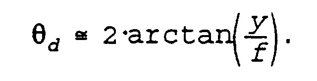
- Figure 1 is a schematic diagram of a focusing multiple-channel, total-reflection optic 10. Only a small representative number of the many radiation transmitting channels are shown. These include outermost channels 12, middle channels 14, and a center channel 16. Radiation 18 incident on the hollow channel portions of the input end 20 of the optic, is guided through the hollow channels as it makes successive total external reflections with the smooth inner channel walls 22. At the output end 24 of the lens, the height of the channels above the optical axis is described by distance y. The outermost channels 12 can be seen to be the maximum distance y from the optical axis 26, while the middle channels 14 are located a shorter distance from axis 26.
- the divergence angle for a particular channel whose output channel axis is a distance y from the optical axis is given approximately by:
- the radiation with the maximum angle of divergence, ⁇ d max comes substantially from the outermost channels 12.
- Figure 2 shows one embodiment of the subject invention, which comprises a multiple-channel, multiple-total-external reflection optic ("optic") 50 designed to focus a received, substantially parallel beam to a small region of space, and a beam stop device or radiation blocking structure 54 disposed at the input end of the optic.
- optic multiple-channel, multiple-total-external reflection optic
- Other optic configurations such as those which capture and focus divergent radiation, or which form a divergent output beam, can also be considered preferred modes depending on the application.
- beam stop device 54 be positioned before input end 56 of the capillary optic. However, it is also possible to locate the beam stop after the optic output end, as described herein below.
- the beam stop 54 is constructed of a radiation-absorbing material, such as stainless steel, and has a radiation transparent aperture of width D. Radiation source properties can effect the ability of the beam stop device to stop the received parallel beam, thus, it is preferred to locate the beam stop device as close as possible, without touching, to the input end of the optic. As can be seen from the figure, the effect of the opaque portion of the beam stop device is to prevent incident radiation 58 from entering the outermost channels 60. Thus, only channels whose output ends are a shorter distance from optical axis 62 transmit incident radiation. Because no radiation passes through the outer channels, the divergence of the output beam at the focal point is determined by the channels which are closer to optical axis 62.
- the net effect is that by selecting which channels radiation is allowed to pass through, the divergence of the output beam at the focal point can be controlled. It is important to note that the spatial extent of the focused spot is essentially not altered by the inclusion of the beam stop device. The spatial extent of the focused spot is determined approximately by the widths of the output ends of the individual channels, or by the widths of individual multiple-channel bundles.
- a second beam stop device could be placed some distance in front of the first. The effect of this second beam stop would be to limit the background radiation passing directly through the channel walls, from reaching the focal point area or the surrounding region.
- Figures 3a, 3b and 3c show a series of interchangeable beam stop devices 80 with radiation transparent apertures D of different diameters.
- the thicknesses, d, of the beam stops which are sufficient to block radiation, varies with the type and energy of radiation to be blocked.
- a preferred beam stop material is stainless steel with a thickness of roughly one centimeter.
- beam stop devices made from 6 Li glass with a thickness of greater than approximately 3 millimeters are preferred.
- other aperture configurations such as square, or rectangular shapes, and other construction materials may also be preferred for particular applications.
- FIG. 4 Shown in Figure 4 is a radiation opaque rotatable wheel 90, which contains a plurality individual beam stop devices 92 each having a different aperture width.
- the wheel turns about an axis 94. Any particular beam stop can be chosen by rotating it into position. There is further flexibility in beam stop aperture size available to the user because individual stops can be removed and replaced on the wheel.
- Figure 5 shows a beam stop device 100 with pivoting leaves 102 which form a continuously variable aperture width for use with x rays.
- the radiation blocking portions be constructed of stainless steel and of sufficient thickness to block x rays with the particular energy for the desired application. If thinner leaves are required, then the stainless steel can be coated with lead or other more absorptive material. The leaves themselves can also be constructed of other more absorptive materials. Adjustments to the aperture width can be done manually, or by a motor.
- Figure 6 shows an adjustable beam stop device 120 that can be used in the subject invention.
- the radiation blocking portions 122 of this beam stop can be made from 6 Li glass plates, which are slidably connected to cross pieces 124 to allow continuous adjustment.
- 6 Li glass is a preferred neutron blocking material for use in combination with multiple-channel, total-reflection optics because, in a preferred embodiment, the optics themselves are made of glass. Since both beam stop and optic are constructed of substantially the same material, contamination complications due to secondary radiation such as gamma rays are kept to a minimum.
- the beam-blocking plates can be made from stainless steel, lead, or other radiation opaque materials. The plates are independently and slidably adjustable. In this configuration, not only is the area of the radiation transmitting aperture variable, but also its shape can change.
- FIG. 7 Yet another embodiment of the subject invention which provides essentially continuous adjustability of the effective radiation-transmitting aperture width of a beam stop device is illustrated in Figure 7 .
- Shown is multiple-channel, total-reflection optic 140, and a single beam stop device 142.
- the optic configuration in this example is designed to capture radiation from an approximate point source of radiation 144, and to focus that radiation to a small spot 146.
- Radiation source 144 is located at the input focal point of the optic, which is located a distance f i , know as the input focal length, from the input end 150 of the optic.
- the distance f o from the optic output end 152 to small focused spot 146 is called the output focal length. Only a few of the many channels of optic 140 are shown, including a pair of outermost channels 154; a pair of middle channels 156; and a central channel 158. It will be seen that when beam stop device 142 is in position A, all the channels of the optic are illuminated by the incident radiation from radiation source 144. Accompanying this maximum channel illumination is a maximum divergence of the focused beam. This maximum divergence is labeled ⁇ A in the figure. When beam stop device 142 is moved to position B, radiation can no longer enter the outermost channels 154 of the optic.
- the divergence angle of the focused radiation beam at the focal point is reduced to ⁇ B .
- the distance of maximum travel of beam stop device 142 along axis 143 is determined as the distance from a point A, where all the optic channels are just illuminated, to a point B, where the beam stop is nearly touching the optic input. In this way, although the radiation-transparent width of the beam stop device remains constant at D, its effective width can be continuously varied.
- the beam stop device can be located after the output end of the lens.
- Figure 8 shows a schematic representation of just such an embodiment of the subject invention. Radiation 202 is incident on the input end 204 of multiple-channel, total-reflection optic 200. Again, only a few representative channels of the many present are pictured. A pair of outermost channels 208, a pair of middle channels 210, and a center channel 212 are shown. Optic 200 of this example is designed to capture a substantially parallel beam of radiation and focus it to a small spot 214, known as the focal point, located a focal distance f from output end 216 of the optic. Beam stop device 218, is located in close proximity to the output end 216 of optic 206.
- Beam stop device 218 can be constructed of a radiation-opaque material of appropriate thickness to efficiently block radiation of the desired type and energy. Beam stop device 218 also has a radiation-transparent aperture of width D. It can be seen from the figure that the effect of beam stop device 218 is to prevent radiation from outermost channels 208 from contributing to the radiation which passes through focal point 214. This again has the effect of changing the divergence of the focused radiation beam. In this embodiment it is desirable to locate the beam stop device as close as possible to, but without touching, output end 216 of the optic.
- FIG. 9 Yet another alternative embodiment of the subject invention, shown in Figure 9 , comprises a beam stop device 240, and a multi-channel, multiplereflection optic 242. Again, only a few of the many optic channels are shown; i.e., a pair of outermost channels 244, a pair of intermediate channels 246, and the central channel 248.
- Optic 242 is designed to efficiently capture radiation 250, from divergent source 252, and to form output beam 254 with a controlled amount of divergence. Divergence of the output beam can be defined as the angle the output radiation makes with optical axis 260.
- the channels at the optic input end 256 all essentially aim at the radiation source 252.
- the divergence of the output beam 254 is dependent on the distance of the radiation transmitting channels from optical axis 260; with the larger the distance, the more divergent the output radiation.
- Beam stop device 240 is disposed in close proximity to optic input end 256, such that radiation is prevented from entering outermost channels 244.
- the dashed radiation lines 262 indicate the path radiation would take if the beam stop device was not present.
Landscapes
- Physics & Mathematics (AREA)
- Spectroscopy & Molecular Physics (AREA)
- Engineering & Computer Science (AREA)
- General Engineering & Computer Science (AREA)
- High Energy & Nuclear Physics (AREA)
- Optical Elements Other Than Lenses (AREA)
- Pressure Welding/Diffusion-Bonding (AREA)
- Ceramic Products (AREA)
- Lenses (AREA)
- Analysing Materials By The Use Of Radiation (AREA)
Description
Claims (8)
- An apparatus for providing a focused radiation beam with controllable convergence, said apparatus comprising:characterised in that said means for varying the angle of convergence comprising a radiation blocking structure (54, 142, 218, 240)a multiple-channel, total-external reflection optic (50, 140, 200, 242) having an input end (56, 150, 204, 256) for receiving radiation, (58,202,250) an output end (57, 152, 216, 258) for providing said focused radiation beam, and an optical axis (62, 143, 260), said focused radiation beam having an angle of convergence () at a focal spot (146,214) a focal length (70,7) from the output end (57, 152, 216, 258) of said optic (50, 140, 200, 242); andmeans for varying the angle of convergence of the focused radiation beam without affecting focal spot size or said focal length (f0, f) of said focal spot (146, 214) from said output end (57, 152, 216, 258) of said optic (50, 140, 200, 242),disposed at said input end (56, 150, 204, 256) of said optic (50, 140, 200, 242) for blocking said radiation from reaching at least some outermost/middle channels (60, 154, 156, 158, 208, 210, 212, 244, 246, 248) of said opticor disposed at said output end (57, 152, 216, 258) of said optic (52, 140, 206, 242) for absorbing radiation exiting at least some outermost/middle channels of said opticsuch that said angle of convergence () of said focused radiation beam at said focal spot (146, 214) spaced said focal length (f0, f) from the output end (57, 152, 216, 258) of said optic is variably adjustable depending on how many outermost/middle channels (60, 154, 156, 158, 208, 210, 212, 244, 246, 248) of said optic are blocked.
- The apparatus of claim 1, wherein said radiation blocking structure includes a radiation transmitting portion, said radiation tramsmitting portion being disposed about said optical axis (62, 143, 260) of said optic (52, 140, 206, 242).
- The apparatus of claim 2, wherein said radiation blocking structure comprises multiple radiation transmitting portions, said radiation transmitting portion disposed about said optical axis comprising one radiation transmitting portion of said multiple radiation transmitting portions, each radiation transmitting portion having one of a unique size and a unique shape, wherein said radiation blocking structure is movable for disposition of any one radiation transmitting portion of said multiple radiation transmitting portions about the optical axis (62, 143, 260), wherein different radiation transmitting portions of said multiple radiation transmitting portions effectuate different angles of convergence of the focused radiation beam at the focal spot (146,214) said focal length (f0,f) from the output end (57, 152, 216, 258) of the optic (52, 140, 206, 242).
- The apparatus according to one of claims 1 to 3, wherein said radiation blocking structure is movable along said optical axis (143), relative to said input end (150) and said output end (216) of said optic (140, 200), respectively, such that said radiation blocking structure blocks different outermost/middle channels (154, 156, 208, 210) of said optic (140, 200), depending upon spacial disposition thereof along said optical axis (143) relative to the input end (150) or the output end (216) of said optic (140, 200), thereby affecting said angle of convergence of the focused radiation beam at the focal spot (146, 214) said focal length (f0,f) from the output end (216) of the optic (140, 200).
- The apparatus according to one of claims 2 to 4, further comprising a plurality of radiation blocking structures, wherein said radiation blocking structure comprises one radiation blocking structure of said plurality of radiation blocking structures, each radiation blocking structure having a radiation transmitting portion of unique size or shape disposed such that when positioned at said input end (150) and said output end (216) of said optic (140, 200), respectively, said radiation transmitting portion is disposed about said optical axis (143) and said radiation blocking structure can block at least some outermost/middle channels (154, 156, 208, 210) of said optic (140, 200), thereby controlling the angle of convergence of said focused radiation beam at said focal spot (146, 214) spaced said focal length (f0,f) from said output end (216) of said optic (140, 200).
- The apparatus according to one of claims 2 to 5, wherein said radiation transmitting portion has at least one of an adjustable size and an adjustable shape such that said radiation transmitting portion intersecting said optical axis (143) is variable within a predetermined range.
- The apparatus of claim 6, wherein said radiation blocking structure comprises a plurality of adjustable opaque sections (102, 122), each adjustable opaque section (102, 122) being capable of blocking radiation, said plurality of adjustable opaque sections (102, 122) cooperating to define said radiation transmitting portion, wherein adjustment of said plurality fo adjustable opaque sections (102, 122) varies at least one of the size and the shape of said radiation transmitting portion disposed about said optical axis (143).
- A method for controlling convergence of a radiation beam, said method comprising the steps of:or absorbing radiation at said output end of said optic from exiting at least some outermost/middle channels of said optic;(a) employing a mulitple-channel, total-external reflection optic to define said radiation beam, said optic having an input end for receiving radiation, and an output end for outputting said radiation beam, said optic being designed such said radiation beam has an angle of convergence at a focal spot a focal length form the output end of the optic; and(b) blocking radiation at said input end of said optic from reaching at least some outermost/middle channels of said optic
such that said angle of convergence of the radiation beam at said focal spot is varied without varying said focal length of said focal spot from the output end of the optic.
Applications Claiming Priority (3)
| Application Number | Priority Date | Filing Date | Title |
|---|---|---|---|
| US08/489,503 US5604353A (en) | 1995-06-12 | 1995-06-12 | Multiple-channel, total-reflection optic with controllable divergence |
| US489503 | 1995-06-12 | ||
| PCT/US1996/010075 WO1996042088A1 (en) | 1995-06-12 | 1996-06-11 | Multiple-channel, total-reflection optic with controllable divergence |
Publications (3)
| Publication Number | Publication Date |
|---|---|
| EP0832491A1 EP0832491A1 (en) | 1998-04-01 |
| EP0832491A4 EP0832491A4 (en) | 1998-07-29 |
| EP0832491B1 true EP0832491B1 (en) | 2002-03-06 |
Family
ID=23944143
Family Applications (1)
| Application Number | Title | Priority Date | Filing Date |
|---|---|---|---|
| EP96923286A Expired - Lifetime EP0832491B1 (en) | 1995-06-12 | 1996-06-11 | Multiple-channel, total-reflection optic with controllable divergence |
Country Status (9)
| Country | Link |
|---|---|
| US (1) | US5604353A (en) |
| EP (1) | EP0832491B1 (en) |
| JP (1) | JP3069865B2 (en) |
| KR (1) | KR100256849B1 (en) |
| CN (1) | CN1147876C (en) |
| AU (1) | AU6383996A (en) |
| DE (1) | DE69619671T2 (en) |
| DK (1) | DK0832491T3 (en) |
| WO (1) | WO1996042088A1 (en) |
Families Citing this family (36)
| Publication number | Priority date | Publication date | Assignee | Title |
|---|---|---|---|---|
| US6271534B1 (en) | 1994-07-08 | 2001-08-07 | Muradin Abubekirovich Kumakhov | Device for producing the image of an object using a flux of neutral or charged particles, and an integrated lens for converting such flux of neutral or charged particles |
| US5838757A (en) * | 1995-10-20 | 1998-11-17 | Michael H. Vartanian & Co., Inc. | Hard x-ray polycapillary telescope |
| GB9815968D0 (en) * | 1998-07-23 | 1998-09-23 | Bede Scient Instr Ltd | X-ray focusing apparatus |
| WO2000024029A1 (en) * | 1998-10-21 | 2000-04-27 | Koninklijke Philips Electronics N.V. | X-ray irradiation apparatus including an x-ray source provided with a capillary optical system |
| US6345086B1 (en) | 1999-09-14 | 2002-02-05 | Veeco Instruments Inc. | X-ray fluorescence system and method |
| EP1402541B1 (en) * | 2001-06-19 | 2006-08-16 | X-Ray Optical Systems, Inc. | Wavelength dispersive xrf system using focusing optic for excitation and a focusing monochromator for collection |
| US6781060B2 (en) | 2002-07-26 | 2004-08-24 | X-Ray Optical Systems Incorporated | Electrical connector, a cable sleeve, and a method for fabricating an electrical connection |
| DE10259696B4 (en) * | 2002-12-18 | 2018-07-05 | Immobiliengesellschaft Helmut Fischer Gmbh & Co. Kg | Device for measuring the thickness of thin layers |
| DE10317679B4 (en) * | 2003-04-17 | 2005-03-31 | Bruker Axs Gmbh | X-ray optical device with wobble device |
| US7023955B2 (en) * | 2003-08-12 | 2006-04-04 | X-Ray Optical System, Inc. | X-ray fluorescence system with apertured mask for analyzing patterned surfaces |
| JP4837964B2 (en) * | 2005-09-28 | 2011-12-14 | 株式会社島津製作所 | X-ray focusing device |
| JP4900660B2 (en) * | 2006-02-21 | 2012-03-21 | 独立行政法人物質・材料研究機構 | X-ray focusing element and X-ray irradiation apparatus |
| US7412131B2 (en) * | 2007-01-02 | 2008-08-12 | General Electric Company | Multilayer optic device and system and method for making same |
| US7366374B1 (en) | 2007-05-22 | 2008-04-29 | General Electric Company | Multilayer optic device and an imaging system and method using same |
| US20090041198A1 (en) * | 2007-08-07 | 2009-02-12 | General Electric Company | Highly collimated and temporally variable x-ray beams |
| US7742566B2 (en) * | 2007-12-07 | 2010-06-22 | General Electric Company | Multi-energy imaging system and method using optic devices |
| CA2720776C (en) * | 2008-04-11 | 2013-07-02 | Rigaku Innovative Technologies, Inc. | X-ray generator with polycapillary optic |
| CN102282629A (en) * | 2008-10-30 | 2011-12-14 | 茵斯派德外科技术公司 | X-ray beam processor |
| US8130908B2 (en) * | 2009-02-23 | 2012-03-06 | X-Ray Optical Systems, Inc. | X-ray diffraction apparatus and technique for measuring grain orientation using x-ray focusing optic |
| US8369674B2 (en) * | 2009-05-20 | 2013-02-05 | General Electric Company | Optimizing total internal reflection multilayer optics through material selection |
| US8208602B2 (en) * | 2010-02-22 | 2012-06-26 | General Electric Company | High flux photon beams using optic devices |
| US8311184B2 (en) | 2010-08-30 | 2012-11-13 | General Electric Company | Fan-shaped X-ray beam imaging systems employing graded multilayer optic devices |
| US8744048B2 (en) | 2010-12-28 | 2014-06-03 | General Electric Company | Integrated X-ray source having a multilayer total internal reflection optic device |
| JP5751665B2 (en) * | 2011-03-01 | 2015-07-22 | 国立研究開発法人理化学研究所 | X-ray distribution device and X-ray distribution system |
| US8761346B2 (en) | 2011-07-29 | 2014-06-24 | General Electric Company | Multilayer total internal reflection optic devices and methods of making and using the same |
| JP6175436B2 (en) | 2011-08-06 | 2017-08-02 | リガク イノベイティブ テクノロジーズ インコーポレイテッド | Nanotube material guide for X-ray photons and neutrons |
| US9057685B2 (en) | 2011-08-15 | 2015-06-16 | X-Ray Optical Systems, Inc. | Sample viscosity and flow control for heavy samples, and X-ray analysis applications thereof |
| CN103946693B (en) | 2011-10-06 | 2017-05-03 | X射线光学系统公司 | Mobile transport and shielding apparatus for removable x-ray analyzer |
| CN103765201B (en) | 2011-10-26 | 2017-11-07 | X射线光学系统公司 | Support structure for the X-ray analysis engine and analyzer and highly aligned monochromatic X-ray optics |
| US9739729B2 (en) | 2012-09-07 | 2017-08-22 | Carl Zeiss X-ray Microscopy, Inc. | Combined confocal X-ray fluorescence and X-ray computerised tomographic system and method |
| WO2015019232A2 (en) * | 2013-08-08 | 2015-02-12 | Controlrad Systems Inc. | X-ray reduction system |
| WO2015027225A1 (en) | 2013-08-23 | 2015-02-26 | The Schepens Eye Research Institute, Inc. | Spatial modeling of visual fields |
| EP3480586B1 (en) * | 2017-11-06 | 2021-02-24 | Bruker Nano GmbH | X-ray fluorescence spectrometer |
| DE102019208834B3 (en) * | 2019-06-18 | 2020-10-01 | Bruker Axs Gmbh | Device for adjusting and changing beam catchers |
| US20220201830A1 (en) | 2020-12-23 | 2022-06-23 | X-Ray Optical Systems, Inc. | X-ray source assembly with enhanced temperature control for output stability |
| US12247934B2 (en) | 2022-07-29 | 2025-03-11 | X-Ray Optical Systems, Inc. | Polarized, energy dispersive x-ray fluorescence system and method |
Family Cites Families (14)
| Publication number | Priority date | Publication date | Assignee | Title |
|---|---|---|---|---|
| FR1318256A (en) * | 1962-03-23 | 1963-02-15 | Atomic Energy Authority Uk | Filtering of penetrating radiation, especially for radiology |
| US3997794A (en) * | 1974-12-23 | 1976-12-14 | York Richard N | Collimator |
| US4143273A (en) * | 1977-04-11 | 1979-03-06 | Ohio-Nuclear, Inc. | Variable collimator |
| US4277684A (en) * | 1977-08-18 | 1981-07-07 | U.S. Philips Corporation | X-Ray collimator, particularly for use in computerized axial tomography apparatus |
| US4158143A (en) * | 1978-04-07 | 1979-06-12 | Bbc Brown, Boveri & Company Limited | Tube for irradiation equipment |
| JPS5630295A (en) * | 1979-08-21 | 1981-03-26 | Oobayashi Seisakusho:Kk | Stop device for x-ray |
| US4450578A (en) * | 1982-03-03 | 1984-05-22 | The United States Of America As Represented By The United States Department Of Energy | Variable aperture collimator for high energy radiation |
| NL8500244A (en) * | 1985-01-29 | 1986-08-18 | Optische Ind De Oude Delft Nv | DEVICE FOR GAP RADIOGRAPHY. |
| JPH02501338A (en) * | 1986-08-15 | 1990-05-10 | コモンウェルス サイエンティフィック アンド インダストリアル リサーチ オーガナイゼイション | Instrumentation for X-ray or neutron beam adjustment |
| US4910759A (en) * | 1988-05-03 | 1990-03-20 | University Of Delaware | Xray lens and collimator |
| US5001737A (en) * | 1988-10-24 | 1991-03-19 | Aaron Lewis | Focusing and guiding X-rays with tapered capillaries |
| US5192869A (en) * | 1990-10-31 | 1993-03-09 | X-Ray Optical Systems, Inc. | Device for controlling beams of particles, X-ray and gamma quanta |
| US5175755A (en) * | 1990-10-31 | 1992-12-29 | X-Ray Optical System, Inc. | Use of a kumakhov lens for x-ray lithography |
| GB9311134D0 (en) * | 1993-05-28 | 1993-07-14 | Univ Leicester | Micro-channel plates |
-
1995
- 1995-06-12 US US08/489,503 patent/US5604353A/en not_active Expired - Lifetime
-
1996
- 1996-06-11 AU AU63839/96A patent/AU6383996A/en not_active Abandoned
- 1996-06-11 DK DK96923286T patent/DK0832491T3/en active
- 1996-06-11 EP EP96923286A patent/EP0832491B1/en not_active Expired - Lifetime
- 1996-06-11 JP JP9503268A patent/JP3069865B2/en not_active Expired - Fee Related
- 1996-06-11 KR KR1019970709362A patent/KR100256849B1/en not_active Expired - Fee Related
- 1996-06-11 CN CNB961962313A patent/CN1147876C/en not_active Expired - Lifetime
- 1996-06-11 DE DE69619671T patent/DE69619671T2/en not_active Expired - Fee Related
- 1996-06-11 WO PCT/US1996/010075 patent/WO1996042088A1/en not_active Ceased
Also Published As
| Publication number | Publication date |
|---|---|
| KR100256849B1 (en) | 2000-05-15 |
| DE69619671D1 (en) | 2002-04-11 |
| JPH11502933A (en) | 1999-03-09 |
| KR19990022893A (en) | 1999-03-25 |
| DK0832491T3 (en) | 2002-06-17 |
| EP0832491A1 (en) | 1998-04-01 |
| CN1192821A (en) | 1998-09-09 |
| DE69619671T2 (en) | 2002-09-12 |
| WO1996042088A1 (en) | 1996-12-27 |
| AU6383996A (en) | 1997-01-09 |
| CN1147876C (en) | 2004-04-28 |
| EP0832491A4 (en) | 1998-07-29 |
| JP3069865B2 (en) | 2000-07-24 |
| US5604353A (en) | 1997-02-18 |
Similar Documents
| Publication | Publication Date | Title |
|---|---|---|
| US5604353A (en) | Multiple-channel, total-reflection optic with controllable divergence | |
| DE69129117T2 (en) | DEVICE FOR CONTROLLING RADIATION AND THEIR USE | |
| KR930702769A (en) | Particle beam, X-ray and sweet-ray control device and its use method | |
| EP1169713B1 (en) | X-ray lens system | |
| US5497008A (en) | Use of a Kumakhov lens in analytic instruments | |
| JP4860418B2 (en) | X-ray optical system | |
| EP0873565B1 (en) | Condenser-monochromator arrangement for x-radiation | |
| MacDonald | Applications and measurements of polycapillary x-ray optics | |
| WO1996023209A1 (en) | X-ray imaging system including a transforming element that selects radiation that forms an image | |
| CA3071142C (en) | Convergent x-ray imaging device and method | |
| Dabagov et al. | Focusing of x-rays by capillary systems | |
| US6996207B2 (en) | X-ray microscope | |
| Owens et al. | Polycapillary X-ray optics for macromolecular crystallography | |
| DE102024002214B4 (en) | Reflection optics and microscope with reflection optics | |
| Wang et al. | Potential of polycapillary optics for hard x-ray medical imaging applications | |
| MacDonald et al. | X-ray optics for better diagnostic imaging | |
| Pease et al. | Log Spiral of Revolution HOPG Monochromator for Fluorescence XAFS | |
| Nikitina et al. | Focusing of quasiparallel beams by means of Kumakhov lenses | |
| HK40022739B (en) | Convergent x-ray imaging device and method | |
| HK40022739A (en) | Convergent x-ray imaging device and method | |
| Padiyar | Characterization of polycapillary x-ray optical systems with potential applications in digital imaging |
Legal Events
| Date | Code | Title | Description |
|---|---|---|---|
| PUAI | Public reference made under article 153(3) epc to a published international application that has entered the european phase |
Free format text: ORIGINAL CODE: 0009012 |
|
| 17P | Request for examination filed |
Effective date: 19971211 |
|
| AK | Designated contracting states |
Kind code of ref document: A1 Designated state(s): CH DE DK FR GB IT LI NL |
|
| RIN1 | Information on inventor provided before grant (corrected) |
Inventor name: DOWNING, ROBERT, GREGORY Inventor name: GIBSON, DAVID, M. |
|
| A4 | Supplementary search report drawn up and despatched |
Effective date: 19980615 |
|
| AK | Designated contracting states |
Kind code of ref document: A4 Designated state(s): CH DE DK FR GB IT LI NL |
|
| 17Q | First examination report despatched |
Effective date: 19991008 |
|
| GRAG | Despatch of communication of intention to grant |
Free format text: ORIGINAL CODE: EPIDOS AGRA |
|
| GRAG | Despatch of communication of intention to grant |
Free format text: ORIGINAL CODE: EPIDOS AGRA |
|
| GRAH | Despatch of communication of intention to grant a patent |
Free format text: ORIGINAL CODE: EPIDOS IGRA |
|
| GRAH | Despatch of communication of intention to grant a patent |
Free format text: ORIGINAL CODE: EPIDOS IGRA |
|
| REG | Reference to a national code |
Ref country code: GB Ref legal event code: IF02 |
|
| GRAA | (expected) grant |
Free format text: ORIGINAL CODE: 0009210 |
|
| AK | Designated contracting states |
Kind code of ref document: B1 Designated state(s): CH DE DK FR GB IT LI NL |
|
| REG | Reference to a national code |
Ref country code: CH Ref legal event code: NV Representative=s name: DIPL.-ING. ETH H. R. WERFFELI PATENTANWALT Ref country code: CH Ref legal event code: EP |
|
| REF | Corresponds to: |
Ref document number: 69619671 Country of ref document: DE Date of ref document: 20020411 |
|
| PGFP | Annual fee paid to national office [announced via postgrant information from national office to epo] |
Ref country code: FR Payment date: 20020617 Year of fee payment: 7 |
|
| REG | Reference to a national code |
Ref country code: DK Ref legal event code: T3 |
|
| PGFP | Annual fee paid to national office [announced via postgrant information from national office to epo] |
Ref country code: DK Payment date: 20020620 Year of fee payment: 7 |
|
| PG25 | Lapsed in a contracting state [announced via postgrant information from national office to epo] |
Ref country code: LI Free format text: LAPSE BECAUSE OF NON-PAYMENT OF DUE FEES Effective date: 20020630 Ref country code: CH Free format text: LAPSE BECAUSE OF NON-PAYMENT OF DUE FEES Effective date: 20020630 |
|
| ET | Fr: translation filed | ||
| PLBE | No opposition filed within time limit |
Free format text: ORIGINAL CODE: 0009261 |
|
| STAA | Information on the status of an ep patent application or granted ep patent |
Free format text: STATUS: NO OPPOSITION FILED WITHIN TIME LIMIT |
|
| REG | Reference to a national code |
Ref country code: CH Ref legal event code: PL |
|
| 26N | No opposition filed |
Effective date: 20021209 |
|
| PG25 | Lapsed in a contracting state [announced via postgrant information from national office to epo] |
Ref country code: DK Free format text: LAPSE BECAUSE OF NON-PAYMENT OF DUE FEES Effective date: 20030630 |
|
| REG | Reference to a national code |
Ref country code: DK Ref legal event code: EBP |
|
| PG25 | Lapsed in a contracting state [announced via postgrant information from national office to epo] |
Ref country code: FR Free format text: LAPSE BECAUSE OF NON-PAYMENT OF DUE FEES Effective date: 20040227 |
|
| REG | Reference to a national code |
Ref country code: FR Ref legal event code: ST |
|
| PG25 | Lapsed in a contracting state [announced via postgrant information from national office to epo] |
Ref country code: IT Free format text: LAPSE BECAUSE OF NON-PAYMENT OF DUE FEES Effective date: 20050611 |
|
| PGFP | Annual fee paid to national office [announced via postgrant information from national office to epo] |
Ref country code: GB Payment date: 20060626 Year of fee payment: 11 |
|
| PGFP | Annual fee paid to national office [announced via postgrant information from national office to epo] |
Ref country code: NL Payment date: 20070618 Year of fee payment: 12 |
|
| PGFP | Annual fee paid to national office [announced via postgrant information from national office to epo] |
Ref country code: DE Payment date: 20070828 Year of fee payment: 12 |
|
| GBPC | Gb: european patent ceased through non-payment of renewal fee |
Effective date: 20070611 |
|
| PG25 | Lapsed in a contracting state [announced via postgrant information from national office to epo] |
Ref country code: GB Free format text: LAPSE BECAUSE OF NON-PAYMENT OF DUE FEES Effective date: 20070611 |
|
| NLV4 | Nl: lapsed or anulled due to non-payment of the annual fee |
Effective date: 20090101 |
|
| PG25 | Lapsed in a contracting state [announced via postgrant information from national office to epo] |
Ref country code: DE Free format text: LAPSE BECAUSE OF NON-PAYMENT OF DUE FEES Effective date: 20090101 |
|
| PG25 | Lapsed in a contracting state [announced via postgrant information from national office to epo] |
Ref country code: NL Free format text: LAPSE BECAUSE OF NON-PAYMENT OF DUE FEES Effective date: 20090101 |