EP0831266B1 - Swivel joint elbow orientation device - Google Patents
Swivel joint elbow orientation device Download PDFInfo
- Publication number
- EP0831266B1 EP0831266B1 EP97202816A EP97202816A EP0831266B1 EP 0831266 B1 EP0831266 B1 EP 0831266B1 EP 97202816 A EP97202816 A EP 97202816A EP 97202816 A EP97202816 A EP 97202816A EP 0831266 B1 EP0831266 B1 EP 0831266B1
- Authority
- EP
- European Patent Office
- Prior art keywords
- elbow member
- angle
- elbow
- swivel joint
- female
- Prior art date
- Legal status (The legal status is an assumption and is not a legal conclusion. Google has not performed a legal analysis and makes no representation as to the accuracy of the status listed.)
- Expired - Lifetime
Links
Images


Classifications
-
- F—MECHANICAL ENGINEERING; LIGHTING; HEATING; WEAPONS; BLASTING
- F16—ENGINEERING ELEMENTS AND UNITS; GENERAL MEASURES FOR PRODUCING AND MAINTAINING EFFECTIVE FUNCTIONING OF MACHINES OR INSTALLATIONS; THERMAL INSULATION IN GENERAL
- F16L—PIPES; JOINTS OR FITTINGS FOR PIPES; SUPPORTS FOR PIPES, CABLES OR PROTECTIVE TUBING; MEANS FOR THERMAL INSULATION IN GENERAL
- F16L27/00—Adjustable joints; Joints allowing movement
- F16L27/08—Adjustable joints; Joints allowing movement allowing adjustment or movement only about the axis of one pipe
- F16L27/0804—Adjustable joints; Joints allowing movement allowing adjustment or movement only about the axis of one pipe the fluid passing axially from one joint element to another
- F16L27/0837—Adjustable joints; Joints allowing movement allowing adjustment or movement only about the axis of one pipe the fluid passing axially from one joint element to another the joint elements being bends
Definitions
- the present invention relates to a dual elbow swivel joint and, more particularly, an orientation device for assisting an operator in establishing a desired relative angle between the female elbow member and the male elbow member.
- Dual elbow swivel joints typically comprise a female elbow member rotationally coupled to a male elbow member, as disclosed for example in US 2 879 083.
- elbow joints are used to convey relatively abrasive materials. Because the elbow joints are used to change the direction of flow of the material, they are subject to substantial erosive wear from the material. It has been found through experimentation and numerical analysis that the degree of wear varies depending on the relative angle between the female elbow member and the male elbow member.
- the present invention is directed to a device for visually indicating the relative angle between the female and male elbow members and the relative degree of wear to be expected at each of a predetermined number of angles.
- the invention comprises a dual elbow swivel joint having a first elbow member rotationally coupled to a second elbow member, comprising
- the angle markings each have a length which is related to the amount of wear that has been found to occur in the dual elbow swivel joint when the female and male members are oriented at that particular angle.
- the orientation device enables an operator to orient the female and male elbow members at an angle at which the dual elbow swivel joint will experience the least amount of wear.
- a conventional dual elbow swivel joint is shown to comprise a tubular female elbow member 12 having an enlarged shroud 14 which is adapted to receive a first end 16 of a tubular male elbow member 18.
- the inner surface of shroud 14 and the outer surface of first end 16 have one or more radial grooves formed therein which, when aligned, define races (not shown) into which bearings are inserted to rotationally couple female elbow member 12 to male elbow member 18.
- female elbow member 12 is defined to have a direction indicated by arrow 22, which is collinear with the centerline of the horizontal straight-line portion 24 of female elbow member 12
- male elbow member 18 is defined to have a direction indicated by arrow 26, which is collinear with the horizontal straight-line portion 28 of male elbow member 18.
- the direction 22 of female elbow member 12 is aligned with the direction 26 of male elbow member 18, that is, the angle between female elbow member 12 and male elbow member 18 is 0°.
- a second analysis was conducted with the direction 22 of female elbow member 12 maintained at an angle A of 45° with respect to the direction 26 of male elbow member 18.
- further analyses were conducted with the direction 22 maintained at angles of 90°, 135° and 180° with respect to the direction 26.
- the dual elbow swivel joint was analyzed with an outlet pipe 30 connected to the female elbow member 12.
- the female elbow member 12 is defined to include an upper elbow 32
- the male elbow member 18 is defined to include a lower elbow 34
- the ball race area between female elbow member 12 and male elbow member 18 is defined as an inlet pipe 36.
- Table 1 presents a listing of the key wear amplitudes and averages in terms of maximum absolute power density, as taken from Figures 2A through 2E.
- Maximum Absolute Power Density Values Female Elbow Relative Angle 0° (S-shaped) 45° 90° 135° 180° (U-shaped) Lower Elbow 3500 3500 3500 3500 3500 Inlet Pipe 5000 5000 5000 4800 4800 Upper Elbow 6100 8000 11600 8000 8300 Outlet Pipe 4500 5200 9200 6500 3400 Mean Over Network 4775 5425 7300 5700 5025 Standard Deviation Over Network 1080 1880 3700 1970 2290 From the results of the analyses, a system was devised which ranks the various orientations of the dual elbow swivel joint according to the wear experienced for each configuration.
- This ranking system is presented in Table 2. As shown in Table 2, several rankings were actually devised: rankings based on the system mean wear values, maximum wear rates in a component, and maximum wear rate multiplied by the area of wear. Thus, if using the system mean ranking system, one can easily discern that the maximum wear occurs when female elbow member 12 is oriented at 90° with respect to male elbow member 18. Similarly, the minimum wear occurs when female elbow member 12 is oriented at 0° relative to male elbow member 18.
- an orientation device is placed on the female and male elbow members 12, 18 to aid an operator in orienting the female elbow member 12 at an angle at which the dual elbow swivel joint 10 will experience minimum wear.
- the orientation device indicated generally by reference number 40, comprises a reference mark 42 and a number of angle markings 44 located either on end 16 of male elbow member 18 (as shown in Figure 1) or on shroud 14 of female elbow member 12.
- Angle markings 44 are preferably located around the circumference of the elbow member at predetermined angles from reference mark 42, as measured from the centerline of the member.
- Orientation device 40 further comprises an indicator mark 46 located on the elbow member opposite the elbow member which includes reference mark 42 and angle markings 44.
- indicator mark 46 is located on shroud 14 of female elbow member 12.
- Reference mark 42 and indicator mark 46 are located on their respective elbow members such that, when they are aligned, female elbow member 12 will be located at a predetermined angle relative to male elbow member 18.
- female elbow member 12 will be oriented 0° with respect to male elbow member 18.
- female elbow member 12 may be oriented at any desired angle relative to male elbow member 18 by aligning indicator mark 46 with the appropriate angle marking 44.
- the angle markings 44 each have a length which is related to the degree of wear experienced in the dual elbow swivel joint at that relative angle.
- the lengths of angle markings 44 at the relative angles are proportional to the system mean ranking values listed in Table 2, as shown in Figure 3. If greater visibility of markings 44 is required, an appropriate multiplier may be applied to the ranking values, or the ranking values may be squared, to increase the length of markings 44 accordingly.
- a curve 48 ( Figure 3) may be constructed from the ranking values (or any desirable multiple or square thereof). In this embodiment, the height or width of the curve provides an indication of the relative angle corresponding to minimum wear without the need for individual angle markings 44. Thus, the degree of wear to be expected in dual elbow swivel joint 10 may be minimized by aligning indicator mark 46 with the shortest angle marking 44 or the portion of curve 48 having the smallest width.
- angle markings 44 or curve 48 may be located on a strip decal applied to the elbow member or a metal band connected to the elbow member by appropriate means.
- Indicator mark 46 may be located on a similar strip decal or band attached to the opposite elbow member, or may be any other suitable marking.
Landscapes
- Engineering & Computer Science (AREA)
- General Engineering & Computer Science (AREA)
- Mechanical Engineering (AREA)
- Joints Allowing Movement (AREA)
- Length Measuring Devices By Optical Means (AREA)
- Pivots And Pivotal Connections (AREA)
Description
- The present invention relates to a dual elbow swivel joint and, more particularly, an orientation device for assisting an operator in establishing a desired relative angle between the female elbow member and the male elbow member.
- Dual elbow swivel joints typically comprise a female elbow member rotationally coupled to a male elbow member, as disclosed for example in US 2 879 083. In certain applications, such as well fractionating operations, elbow joints are used to convey relatively abrasive materials. Because the elbow joints are used to change the direction of flow of the material, they are subject to substantial erosive wear from the material. It has been found through experimentation and numerical analysis that the degree of wear varies depending on the relative angle between the female elbow member and the male elbow member.
- Various systems of tubular joints are known in which the relative angular positions of adjacent joint sections are indicated by means of visible scale markings. An example is DE 39 37 645 concerning a system of tubular members for securing liquid carrying hoses in place in motor cars. However, in none of these prior joint systems is the relative angular orientation of the joint parts related to erosive wear rates.
- The present invention is directed to a device for visually indicating the relative angle between the female and male elbow members and the relative degree of wear to be expected at each of a predetermined number of angles. Thus, the invention comprises a dual elbow swivel joint having a first elbow member rotationally coupled to a second elbow member, comprising
- an indicator mark located on the first elbow member;
- a plurality of angle markings located on the second elbow member adjacent the first elbow member, the angle markings each corresponding to a predetermined relative angle between the first elbow member and the second elbow member;
- wherein the first elbow member may be oriented at a desired angle relative to the second elbow member by aligning the indicator mark with an angle marking corresponding to the desired angle; characterised in that the angle markings form a scale which co-operates with the indicator mark to indicate the degree of wear experienced in the swivel joint.
-
- In a preferred aspect of the invention, the angle markings each have a length which is related to the amount of wear that has been found to occur in the dual elbow swivel joint when the female and male members are oriented at that particular angle. Thus, the orientation device enables an operator to orient the female and male elbow members at an angle at which the dual elbow swivel joint will experience the least amount of wear.
- These and other objects and advantages of the present invention will be made apparent from the following detailed description, with reference to the accompanying drawings.
-
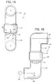
- Figures 1A and 1B are front and side elevation views, respectively, of a dual elbow swivel joint incorporating the angle marker of the present invention ;
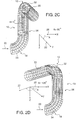
- Figures 2A through 2E are perspective representations showing the maximum wear zones experienced during testing of a dual elbow swivel joint for various angular orientations of the female and male elbow members; and
- Figure 3 is a depiction of the angle marker of the present invention.
-
- Referring to Figure 1, a conventional dual elbow swivel joint, indicated generally by
reference number 10, is shown to comprise a tubularfemale elbow member 12 having an enlargedshroud 14 which is adapted to receive afirst end 16 of a tubularmale elbow member 18. The inner surface ofshroud 14 and the outer surface offirst end 16 have one or more radial grooves formed therein which, when aligned, define races (not shown) into which bearings are inserted to rotationally couplefemale elbow member 12 tomale elbow member 18. For purposes of this description, when material is assumed to flow through dualelbow swivel joint 10 in the direction indicated byarrow 20,female elbow member 12 is defined to have a direction indicated byarrow 22, which is collinear with the centerline of the horizontal straight-line portion 24 offemale elbow member 12, andmale elbow member 18 is defined to have a direction indicated byarrow 26, which is collinear with the horizontal straight-line portion 28 ofmale elbow member 18. Thus, in Figure 1B thedirection 22 offemale elbow member 12 is aligned with thedirection 26 ofmale elbow member 18, that is, the angle betweenfemale elbow member 12 andmale elbow member 18 is 0°. - Through experimentation and numerical analysis, it has been discovered that the wear patterns and rates experienced in a dual elbow swivel joint vary depending on the relative angle between the female and
male elbow members swivel joint 10 similar to that depicted in Figure 1 was analyzed with thefemale elbow member 12 oriented at different angles relative tomale elbow member 18. As shown in Figure 2A, a first analysis was conducted with thedirection 22 offemale elbow member 12 maintained at an angle A of 0° with respect to thedirection 26 ofmale elbow member 18. As shown in Figure 28, a second analysis was conducted with thedirection 22 offemale elbow member 12 maintained at an angle A of 45° with respect to thedirection 26 ofmale elbow member 18. As shown in Figures 2C through 2E, further analyses were conducted with thedirection 22 maintained at angles of 90°, 135° and 180° with respect to thedirection 26. The dual elbow swivel joint was analyzed with anoutlet pipe 30 connected to thefemale elbow member 12. Also, for purposes of the following description, thefemale elbow member 12 is defined to include anupper elbow 32, themale elbow member 18 is defined to include alower elbow 34, and the ball race area betweenfemale elbow member 12 andmale elbow member 18 is defined as aninlet pipe 36. - During tests to establish the parameters for the above-mentioned analyses, a frac-fluid with 1440 kgm-3 (12 lbm/gallon) 16-20 proppant was introduced into the swivel joint at a nominal flow velocity of 13.7 ms-1 (45 ft/sec) in the direction shown by
arrow 20. From the results of the analyses, the maximum wear zones for each configuration were determined. These maximum wear zones are depicted assolid areas 38 on each dual elbow swivel joint shown in Figures 2A through 2E. The hatched areas adjacent thesolid areas 38 show the extent of the wear zone for 80% of the maximum wear value. The results of the analyses are summarized in Table 1, which presents a listing of the key wear amplitudes and averages in terms of maximum absolute power density, as taken from Figures 2A through 2E.Maximum Absolute Power Density Values Female Elbow Relative Angle 0° (S-shaped) 45° 90° 135° 180° (U-shaped) Lower Elbow 3500 3500 3500 3500 3500 Inlet Pipe 5000 5000 5000 4800 4800 Upper Elbow 6100 8000 11600 8000 8300 Outlet Pipe 4500 5200 9200 6500 3400 Mean Over Network 4775 5425 7300 5700 5025 Standard Deviation Over Network 1080 1880 3700 1970 2290 female elbow member 12 is oriented at 90° with respect tomale elbow member 18. Similarly, the minimum wear occurs whenfemale elbow member 12 is oriented at 0° relative tomale elbow member 18.Rankings of Configurations for Wear Reduction
Scale: 1 (least wear) to 5 (most wear)Female Elbow
Relative Angle0°
(S-shaped)45° 90° 135° 180°
(U-shaped)System Mean 1 3 5 4 2 Maximum Wear in System Component 1 2 5,4 2 3 Maximum Wear Rate x Area Extent 1 2 3,4 5 3,4 - According to an embodiment of the present invention, an orientation device is placed on the female and
male elbow members female elbow member 12 at an angle at which the dual elbowswivel joint 10 will experience minimum wear. Referring to Figures 1 and 3, the orientation device, indicated generally byreference number 40, comprises areference mark 42 and a number ofangle markings 44 located either onend 16 of male elbow member 18 (as shown in Figure 1) or onshroud 14 offemale elbow member 12.Angle markings 44 are preferably located around the circumference of the elbow member at predetermined angles fromreference mark 42, as measured from the centerline of the member.Orientation device 40 further comprises anindicator mark 46 located on the elbow member opposite the elbow member which includesreference mark 42 andangle markings 44. For example, in the embodiment depicted in Figure 1,indicator mark 46 is located onshroud 14 offemale elbow member 12.Reference mark 42 andindicator mark 46 are located on their respective elbow members such that, when they are aligned,female elbow member 12 will be located at a predetermined angle relative tomale elbow member 18. As shown in Figure 1, whenreference mark 42 andindicator mark 46 are aligned,female elbow member 12 will be oriented 0° with respect tomale elbow member 18. Thus,female elbow member 12 may be oriented at any desired angle relative tomale elbow member 18 by aligningindicator mark 46 with the appropriate angle marking 44. - The
angle markings 44 each have a length which is related to the degree of wear experienced in the dual elbow swivel joint at that relative angle. In a preferred embodiment of the invention, the lengths ofangle markings 44 at the relative angles are proportional to the system mean ranking values listed in Table 2, as shown in Figure 3. If greater visibility ofmarkings 44 is required, an appropriate multiplier may be applied to the ranking values, or the ranking values may be squared, to increase the length ofmarkings 44 accordingly. In a further embodiment of the invention, a curve 48 (Figure 3) may be constructed from the ranking values (or any desirable multiple or square thereof). In this embodiment, the height or width of the curve provides an indication of the relative angle corresponding to minimum wear without the need forindividual angle markings 44. Thus, the degree of wear to be expected in dual elbow swivel joint 10 may be minimized by aligningindicator mark 46 with the shortest angle marking 44 or the portion ofcurve 48 having the smallest width. - In practice,
angle markings 44 orcurve 48 may be located on a strip decal applied to the elbow member or a metal band connected to the elbow member by appropriate means.Indicator mark 46 may be located on a similar strip decal or band attached to the opposite elbow member, or may be any other suitable marking.
Claims (3)
- A dual elbow swivel joint (10) having a first elbow member (12) rotationally coupled to a second elbow member (18), comprisingcharacterised in that the angle markings (42, 44) form a scale which co-operates with the indicator mark (46) to indicate the degree of wear experienced in the swivel joint (10).an indicator mark (46) located on the first elbow member;a plurality of angle markings (42, 44) located on the second elbow member adjacent the first elbow member, the angle markings (42, 44) each corresponding to a predetermined relative angle between the first elbow member (12) and the second elbow member (18);wherein the first elbow member (12) may be oriented at a desired angle relative to the second elbow member (18) by aligning the indicator mark (46) with an angle marking (42, 44) corresponding to the desired angle;
- The swivel joint of claim 1, further characterised in that the angle markings (44) each comprise a length relating to a relative degree of wear experienced in the swivel joint (10) when the first elbow member (12) is oriented relative to the second elbow member (18) at the predetermined angle corresponding to the angle marking (44).
- The swivel joint of claim 2, further characterised in that the angle markings (44) define a curve having a width at a particular angle marking (44) proportional to the length of the angle marking (44).
Applications Claiming Priority (2)
| Application Number | Priority Date | Filing Date | Title |
|---|---|---|---|
| US717380 | 1996-09-23 | ||
| US08/717,380 US5720501A (en) | 1996-09-23 | 1996-09-23 | Swivel joint elbow orientation device |
Publications (3)
| Publication Number | Publication Date |
|---|---|
| EP0831266A2 EP0831266A2 (en) | 1998-03-25 |
| EP0831266A3 EP0831266A3 (en) | 1999-05-19 |
| EP0831266B1 true EP0831266B1 (en) | 2001-11-14 |
Family
ID=24881798
Family Applications (1)
| Application Number | Title | Priority Date | Filing Date |
|---|---|---|---|
| EP97202816A Expired - Lifetime EP0831266B1 (en) | 1996-09-23 | 1997-09-15 | Swivel joint elbow orientation device |
Country Status (7)
| Country | Link |
|---|---|
| US (1) | US5720501A (en) |
| EP (1) | EP0831266B1 (en) |
| JP (1) | JPH10185045A (en) |
| BR (1) | BR9702909A (en) |
| CA (1) | CA2216073A1 (en) |
| DE (1) | DE69708241D1 (en) |
| NO (1) | NO974370L (en) |
Families Citing this family (15)
| Publication number | Priority date | Publication date | Assignee | Title |
|---|---|---|---|---|
| FI3316U1 (en) * | 1997-10-27 | 1998-02-26 | Ari C O Helka Sankal Penttilae | Pipe fittings of a piping system |
| US6098346A (en) * | 1997-12-01 | 2000-08-08 | Newmar Corporation | Slide out kitchen for motor homes and the like |
| EP1148284A1 (en) * | 2000-04-18 | 2001-10-24 | Von Roll Holding AG | Articulated pipe joint |
| DE10120266B4 (en) * | 2001-04-25 | 2005-07-28 | Veritas Ag | Tube with at least one marking, method for mounting a sleeve on this tube and its use |
| US6581974B1 (en) | 2001-09-29 | 2003-06-24 | Ragner Manufacturing, Llc | Pivot adaptor attachment for vacuum cleaners |
| US8407853B1 (en) * | 2006-10-12 | 2013-04-02 | John Baxt | High place vacuum cleaner attachment |
| US20080231048A1 (en) * | 2007-03-22 | 2008-09-25 | Norgren, Inc. | Pneumatic swivel elbow |
| US20080296007A1 (en) * | 2007-05-31 | 2008-12-04 | Richard Kenneth Harris | Low profile heater core connector |
| EP3338845B1 (en) * | 2008-04-10 | 2021-10-06 | Seattle Children's Hospital d/b/a Seattle Children's Research Institute | Broad-band, low frequency, high-amplitude, long time duration, oscillating airway pressure breathing apparatus |
| US10927991B2 (en) * | 2013-07-22 | 2021-02-23 | Miraial Co., Ltd. | Weld fitting |
| BR202013028688U2 (en) * | 2013-11-07 | 2016-10-04 | Gustaviano Martins De Almeida | arrangement applied to pipes and hydraulic connections |
| US10774965B1 (en) | 2017-03-02 | 2020-09-15 | KHOLLE Magnolia 2015, LLC | Flowline component with rotatable flange on retainer segments |
| US10995561B1 (en) | 2017-03-02 | 2021-05-04 | KHOLLE Magnolia 2015, LLC | Flowline component with threaded rotatable flange |
| US11598426B2 (en) * | 2019-11-15 | 2023-03-07 | Kadant Johnson Llc | Rotary joint shroud having set-up gauge and seal wear indicator |
| US12320459B2 (en) * | 2022-04-12 | 2025-06-03 | Caterpillar Inc. | Conduit coupling with indicator of bend plane |
Family Cites Families (8)
| Publication number | Priority date | Publication date | Assignee | Title |
|---|---|---|---|---|
| US2879083A (en) * | 1953-11-16 | 1959-03-24 | Youngstown Sheet And Tube Co | High pressure swivel connector for adjustable conduits with strain relief means |
| US3480300A (en) * | 1966-02-24 | 1969-11-25 | Mcwane Cast Iron Pipe Co | Pipe coupling |
| US4077657A (en) * | 1976-03-22 | 1978-03-07 | Smith, International, Inc. | Adjustable bent sub |
| US4098695A (en) * | 1977-04-27 | 1978-07-04 | Industrial Filter & Pump Mfg. Co. | Distributor-collector assembly |
| ZA831190B (en) * | 1982-02-27 | 1983-11-30 | Quayville Pty Ltd | Variable angle joint |
| DE3937645C2 (en) * | 1989-11-11 | 1997-04-30 | Bayerische Motoren Werke Ag | Device for defining curved lines |
| US5044674A (en) * | 1990-08-03 | 1991-09-03 | Quikcoup, Inc. | Angularly adjustable pipe connector |
| US5242112A (en) * | 1992-07-20 | 1993-09-07 | Hunter Industries | Swing connector for sprinkler |
-
1996
- 1996-09-23 US US08/717,380 patent/US5720501A/en not_active Expired - Fee Related
-
1997
- 1997-09-15 DE DE69708241T patent/DE69708241D1/en not_active Expired - Lifetime
- 1997-09-15 EP EP97202816A patent/EP0831266B1/en not_active Expired - Lifetime
- 1997-09-19 CA CA002216073A patent/CA2216073A1/en not_active Abandoned
- 1997-09-22 NO NO974370A patent/NO974370L/en not_active Application Discontinuation
- 1997-09-23 BR BR9702909A patent/BR9702909A/en not_active Application Discontinuation
- 1997-09-24 JP JP9258343A patent/JPH10185045A/en active Pending
Also Published As
| Publication number | Publication date |
|---|---|
| JPH10185045A (en) | 1998-07-14 |
| BR9702909A (en) | 1998-12-22 |
| US5720501A (en) | 1998-02-24 |
| NO974370L (en) | 1998-03-24 |
| CA2216073A1 (en) | 1998-03-23 |
| NO974370D0 (en) | 1997-09-22 |
| EP0831266A2 (en) | 1998-03-25 |
| EP0831266A3 (en) | 1999-05-19 |
| DE69708241D1 (en) | 2001-12-20 |
Similar Documents
| Publication | Publication Date | Title |
|---|---|---|
| US5720501A (en) | Swivel joint elbow orientation device | |
| US7500699B2 (en) | Clamping mechanical pipe coupling derived from a standard fitting | |
| US4955645A (en) | Gauging device and method for coupling threaded, tubular articles and a coupling assembly | |
| US6732445B1 (en) | Pipe fitting apparatus, method, and product-by process for taking simultaneous linear and angular measurements | |
| US6505412B2 (en) | Pipefitter's protractor | |
| US5044303A (en) | Sub-surface conduit marking apparatus | |
| JPH07508213A (en) | Mixing device for two fluids with different temperatures | |
| US5039011A (en) | Underground connectors for sprinkler systems | |
| US20010004153A1 (en) | Infinitely selectable angle pipe fitting | |
| US4835873A (en) | Gauging device and method for coupling threaded, tubular articles and a coupling assembly | |
| DE3623420A1 (en) | DEVICE FOR SUPPLYING A CRYOGENIC REFRIGERANT TO THE PROCESSING ZONE OF A ROBOT | |
| EP1293759A2 (en) | Apparatus for measuring the speed and/or the flow rate of a fluid | |
| JP3093207B2 (en) | Wear indicator for tubular joints | |
| US6692035B2 (en) | Device and method for coupling pipes | |
| US20040222626A1 (en) | Device and method for coupling pipes | |
| EP1398552B1 (en) | Pivoting support for a pipe | |
| US4618378A (en) | Pipe cutting templet | |
| DE69607841T2 (en) | METHOD AND DEVICE FOR LAYING PIPES | |
| US5056834A (en) | System for joining corrugated pipe | |
| NZ507058A (en) | Internally lined with plastic to prevent corrosion for an irrigated water system | |
| US583926A (en) | Conduit | |
| US4274765A (en) | Mining equipment | |
| FI131207B1 (en) | A connecting arrangement for a hose | |
| US4404726A (en) | Method of connecting flexible tubular duct and a connector | |
| WO1997033118A1 (en) | Elbow tee fitting |
Legal Events
| Date | Code | Title | Description |
|---|---|---|---|
| PUAI | Public reference made under article 153(3) epc to a published international application that has entered the european phase |
Free format text: ORIGINAL CODE: 0009012 |
|
| 17P | Request for examination filed |
Effective date: 19970915 |
|
| AK | Designated contracting states |
Kind code of ref document: A2 Designated state(s): DE FR GB |
|
| AX | Request for extension of the european patent |
Free format text: AL;LT;LV;RO;SI |
|
| PUAL | Search report despatched |
Free format text: ORIGINAL CODE: 0009013 |
|
| AK | Designated contracting states |
Kind code of ref document: A3 Designated state(s): AT BE CH DE DK ES FI FR GB GR IE IT LI LU MC NL PT SE |
|
| AX | Request for extension of the european patent |
Free format text: AL;LT;LV;RO;SI |
|
| AKX | Designation fees paid |
Free format text: DE FR GB |
|
| GRAG | Despatch of communication of intention to grant |
Free format text: ORIGINAL CODE: EPIDOS AGRA |
|
| 17Q | First examination report despatched |
Effective date: 20001116 |
|
| GRAG | Despatch of communication of intention to grant |
Free format text: ORIGINAL CODE: EPIDOS AGRA |
|
| GRAH | Despatch of communication of intention to grant a patent |
Free format text: ORIGINAL CODE: EPIDOS IGRA |
|
| GRAH | Despatch of communication of intention to grant a patent |
Free format text: ORIGINAL CODE: EPIDOS IGRA |
|
| GRAA | (expected) grant |
Free format text: ORIGINAL CODE: 0009210 |
|
| AK | Designated contracting states |
Kind code of ref document: B1 Designated state(s): DE FR GB |
|
| PG25 | Lapsed in a contracting state [announced via postgrant information from national office to epo] |
Ref country code: FR Free format text: LAPSE BECAUSE OF FAILURE TO SUBMIT A TRANSLATION OF THE DESCRIPTION OR TO PAY THE FEE WITHIN THE PRESCRIBED TIME-LIMIT Effective date: 20011114 |
|
| REF | Corresponds to: |
Ref document number: 69708241 Country of ref document: DE Date of ref document: 20011220 |
|
| REG | Reference to a national code |
Ref country code: GB Ref legal event code: IF02 |
|
| PG25 | Lapsed in a contracting state [announced via postgrant information from national office to epo] |
Ref country code: DE Free format text: LAPSE BECAUSE OF FAILURE TO SUBMIT A TRANSLATION OF THE DESCRIPTION OR TO PAY THE FEE WITHIN THE PRESCRIBED TIME-LIMIT Effective date: 20020215 |
|
| PG25 | Lapsed in a contracting state [announced via postgrant information from national office to epo] |
Ref country code: GB Free format text: LAPSE BECAUSE OF NON-PAYMENT OF DUE FEES Effective date: 20020915 |
|
| PLBE | No opposition filed within time limit |
Free format text: ORIGINAL CODE: 0009261 |
|
| STAA | Information on the status of an ep patent application or granted ep patent |
Free format text: STATUS: NO OPPOSITION FILED WITHIN TIME LIMIT |
|
| EN | Fr: translation not filed | ||
| 26N | No opposition filed | ||
| GBPC | Gb: european patent ceased through non-payment of renewal fee |
Effective date: 20020915 |