EP0830541B1 - Illumination assembly for dental and medical applications - Google Patents
Illumination assembly for dental and medical applications Download PDFInfo
- Publication number
- EP0830541B1 EP0830541B1 EP96920423A EP96920423A EP0830541B1 EP 0830541 B1 EP0830541 B1 EP 0830541B1 EP 96920423 A EP96920423 A EP 96920423A EP 96920423 A EP96920423 A EP 96920423A EP 0830541 B1 EP0830541 B1 EP 0830541B1
- Authority
- EP
- European Patent Office
- Prior art keywords
- illumination
- illumination assembly
- housing
- light guide
- user
- Prior art date
- Legal status (The legal status is an assumption and is not a legal conclusion. Google has not performed a legal analysis and makes no representation as to the accuracy of the status listed.)
- Expired - Lifetime
Links
- 238000005286 illumination Methods 0.000 title claims abstract description 177
- 230000003287 optical effect Effects 0.000 claims abstract description 49
- 241000282461 Canis lupus Species 0.000 abstract description 8
- 210000003128 head Anatomy 0.000 description 26
- 230000000712 assembly Effects 0.000 description 22
- 238000000429 assembly Methods 0.000 description 22
- 239000011521 glass Substances 0.000 description 9
- 239000004033 plastic Substances 0.000 description 9
- 230000004438 eyesight Effects 0.000 description 7
- 239000000835 fiber Substances 0.000 description 5
- SYJPAKDNFZLSMV-HYXAFXHYSA-N (Z)-2-methylpropanal oxime Chemical compound CC(C)\C=N/O SYJPAKDNFZLSMV-HYXAFXHYSA-N 0.000 description 4
- 239000004727 Noryl Substances 0.000 description 4
- 229920001207 Noryl Polymers 0.000 description 4
- 239000002184 metal Substances 0.000 description 4
- 239000000853 adhesive Substances 0.000 description 3
- 230000001070 adhesive effect Effects 0.000 description 3
- 239000000919 ceramic Substances 0.000 description 3
- 210000001061 forehead Anatomy 0.000 description 3
- 238000000034 method Methods 0.000 description 3
- 230000005855 radiation Effects 0.000 description 3
- 239000000126 substance Substances 0.000 description 3
- 230000005540 biological transmission Effects 0.000 description 2
- 238000004140 cleaning Methods 0.000 description 2
- 238000010276 construction Methods 0.000 description 2
- 238000010438 heat treatment Methods 0.000 description 2
- 238000003780 insertion Methods 0.000 description 2
- 230000037431 insertion Effects 0.000 description 2
- 239000007788 liquid Substances 0.000 description 2
- 230000005043 peripheral vision Effects 0.000 description 2
- 238000005201 scrubbing Methods 0.000 description 2
- 241000282887 Suidae Species 0.000 description 1
- 230000015556 catabolic process Effects 0.000 description 1
- 229910010293 ceramic material Inorganic materials 0.000 description 1
- 239000002131 composite material Substances 0.000 description 1
- 230000036461 convulsion Effects 0.000 description 1
- 238000001816 cooling Methods 0.000 description 1
- 238000006731 degradation reaction Methods 0.000 description 1
- 238000005553 drilling Methods 0.000 description 1
- 230000003670 easy-to-clean Effects 0.000 description 1
- 239000012530 fluid Substances 0.000 description 1
- 230000001771 impaired effect Effects 0.000 description 1
- 238000010348 incorporation Methods 0.000 description 1
- 230000002452 interceptive effect Effects 0.000 description 1
- 239000000463 material Substances 0.000 description 1
- 210000000214 mouth Anatomy 0.000 description 1
- 239000002245 particle Substances 0.000 description 1
- 230000008092 positive effect Effects 0.000 description 1
- 238000004382 potting Methods 0.000 description 1
- 238000003825 pressing Methods 0.000 description 1
- 239000012858 resilient material Substances 0.000 description 1
- 229920002379 silicone rubber Polymers 0.000 description 1
- 239000004945 silicone rubber Substances 0.000 description 1
- 229910001220 stainless steel Inorganic materials 0.000 description 1
- 239000010935 stainless steel Substances 0.000 description 1
- 238000002604 ultrasonography Methods 0.000 description 1
Images


Classifications
-
- F—MECHANICAL ENGINEERING; LIGHTING; HEATING; WEAPONS; BLASTING
- F21—LIGHTING
- F21V—FUNCTIONAL FEATURES OR DETAILS OF LIGHTING DEVICES OR SYSTEMS THEREOF; STRUCTURAL COMBINATIONS OF LIGHTING DEVICES WITH OTHER ARTICLES, NOT OTHERWISE PROVIDED FOR
- F21V21/00—Supporting, suspending, or attaching arrangements for lighting devices; Hand grips
- F21V21/08—Devices for easy attachment to any desired place, e.g. clip, clamp, magnet
- F21V21/084—Head fittings
-
- G—PHYSICS
- G02—OPTICS
- G02B—OPTICAL ELEMENTS, SYSTEMS OR APPARATUS
- G02B25/00—Eyepieces; Magnifying glasses
- G02B25/002—Magnifying glasses
- G02B25/004—Magnifying glasses having binocular arrangement
-
- G—PHYSICS
- G02—OPTICS
- G02B—OPTICAL ELEMENTS, SYSTEMS OR APPARATUS
- G02B6/00—Light guides; Structural details of arrangements comprising light guides and other optical elements, e.g. couplings
- G02B6/0001—Light guides; Structural details of arrangements comprising light guides and other optical elements, e.g. couplings specially adapted for lighting devices or systems
- G02B6/0005—Light guides; Structural details of arrangements comprising light guides and other optical elements, e.g. couplings specially adapted for lighting devices or systems the light guides being of the fibre type
- G02B6/0008—Light guides; Structural details of arrangements comprising light guides and other optical elements, e.g. couplings specially adapted for lighting devices or systems the light guides being of the fibre type the light being emitted at the end of the fibre
-
- G—PHYSICS
- G02—OPTICS
- G02B—OPTICAL ELEMENTS, SYSTEMS OR APPARATUS
- G02B7/00—Mountings, adjusting means, or light-tight connections, for optical elements
- G02B7/002—Mounting on the human body
-
- G—PHYSICS
- G02—OPTICS
- G02C—SPECTACLES; SUNGLASSES OR GOGGLES INSOFAR AS THEY HAVE THE SAME FEATURES AS SPECTACLES; CONTACT LENSES
- G02C11/00—Non-optical adjuncts; Attachment thereof
- G02C11/04—Illuminating means
-
- G—PHYSICS
- G02—OPTICS
- G02C—SPECTACLES; SUNGLASSES OR GOGGLES INSOFAR AS THEY HAVE THE SAME FEATURES AS SPECTACLES; CONTACT LENSES
- G02C7/00—Optical parts
- G02C7/02—Lenses; Lens systems ; Methods of designing lenses
- G02C7/08—Auxiliary lenses; Arrangements for varying focal length
- G02C7/088—Lens systems mounted to spectacles
-
- F—MECHANICAL ENGINEERING; LIGHTING; HEATING; WEAPONS; BLASTING
- F21—LIGHTING
- F21V—FUNCTIONAL FEATURES OR DETAILS OF LIGHTING DEVICES OR SYSTEMS THEREOF; STRUCTURAL COMBINATIONS OF LIGHTING DEVICES WITH OTHER ARTICLES, NOT OTHERWISE PROVIDED FOR
- F21V21/00—Supporting, suspending, or attaching arrangements for lighting devices; Hand grips
- F21V21/14—Adjustable mountings
- F21V21/145—Adjustable mountings for portable lighting devices
-
- G—PHYSICS
- G02—OPTICS
- G02C—SPECTACLES; SUNGLASSES OR GOGGLES INSOFAR AS THEY HAVE THE SAME FEATURES AS SPECTACLES; CONTACT LENSES
- G02C2200/00—Generic mechanical aspects applicable to one or more of the groups G02C1/00 - G02C5/00 and G02C9/00 - G02C13/00 and their subgroups
- G02C2200/02—Magnetic means
-
- Y—GENERAL TAGGING OF NEW TECHNOLOGICAL DEVELOPMENTS; GENERAL TAGGING OF CROSS-SECTIONAL TECHNOLOGIES SPANNING OVER SEVERAL SECTIONS OF THE IPC; TECHNICAL SUBJECTS COVERED BY FORMER USPC CROSS-REFERENCE ART COLLECTIONS [XRACs] AND DIGESTS
- Y10—TECHNICAL SUBJECTS COVERED BY FORMER USPC
- Y10S—TECHNICAL SUBJECTS COVERED BY FORMER USPC CROSS-REFERENCE ART COLLECTIONS [XRACs] AND DIGESTS
- Y10S362/00—Illumination
- Y10S362/804—Surgical or dental spotlight
Definitions
- the invention relates generally to the field of head-mounted illumination devices for medical and dental use, and specifically to the field of small, lightweight, high intensity illumination assemblies for medical and dental use which are mounted on the user's head to provide coaxial illumination.
- Such an assembly is disclosed in US-A-3285242.
- the illumination beam supplied by the illumination assembly should correspond as closely as possible to the user's line of vision, i.e., the illumination assembly should illuminate the patient or workpiece from a point as close to the user's eyes as possible (preferably from immediately between the eyes). Otherwise, the user's hands, arms, or any other objects may obstruct the light path and cast shadows upon the patient or workpiece. Also, dentists and medical personnel often have a need to look into very small holes, such as holes drilled into teeth, and the interior of such holes generally cannot be viewed without direct illumination along the axis of the hole.
- the illumination source is mounted near the user's eyes and emits a beam of illumination which is parallel to and very nearly coaxial with the user's line of sight, the chances for the creation of shadows is minimised. Additionally, such a mounting position ensures that the user will automatically illuminate any area that the user views provided the user's head is directed toward that area.
- the illumination assembly should be safe and comfortable to wear.
- Some prior art devices include light sources mounted on a user's head or headgear, such as those of U.S. Patent 3,350,552 to Lawrence and U.S. Patent 5,341,513 to Klein et al , which respectively illustrate lamps mounted to eyeglasses and a headband. These devices have proven to be disadvantageous in that they can create a great deal of heat at a point close to the user's head, especially if high-intensity lightbulbs are used.
- the illumination assembly should be capable of use on different parts of the user's head, and should also be capable of being adjustably positioned to illuminate different desired areas.
- Many of the prior art illumination assemblies are not very versatile because they are permanently mounted within already existing headgear, such as the illumination devices of Cooley et al . and Price, which show eyeglasses with illumination elements at opposing sides of the eyeglass frames adjacent the support legs. These devices can neither be used without the associated headgear nor repositioned to illuminate different areas of the patient or workpiece.
- an illumination assembly is permanently affixed to headgear such as eyeglasses, headbands, face shields, etc., it is often difficult to use a second type of headgear in conjunction with the first type of headgear and the illumination assembly.
- a face shield can either scatter or entirely obstruct the light emitted from the devices of Price and Cooley et al .
- the illumination assembly since the illumination assembly may become contaminated with particles from the patient or workpiece or fluids splashing therefrom, the illumination assembly should be easy to clean.
- the illumination assembly should produce an illuminated spot of high and uniform intensity.
- a small, bright spot is extremely important to most medical and dental applications, such as when the interior of a cavity must be viewed (e.g., the interior of a hole drilled within a tooth). In that case, full illumination of the cavity is desired with minimum illumination of the surrounding area outside the cavity.
- the spot size should also be variable in order to allow the user to tailor the spot size to fit the area to be illuminated.
- U.S. Patent 4,104,709 to Kloots describes an illumination device which provides a continuously variable spot size, as does U.S. Patent 3,285,242 to Wallace .
- the weight of the illumination assembly should be small enough that the headgear does not dig into the user's head and so that the user is virtually unaware of its presence on the user's head.
- the prior art illumination assemblies tend to be quite heavy due to their use of several optical elements (lenses, prisms, mirrors, etc.) and means for mounting these optical elements within the illumination assembly.
- the several optical elements are required in order to produce a properly sized, well-defined, uniform spot, especially in the illumination assemblies which allow for a variable spot size (e.g., the aforementioned patent to Wallace and U.S. Patent 4,104,709 to Kloots ).
- the optical elements must generally be made of heavy, high-grade refractive glass to decrease their size and increase their optical quality, the optical elements comprise a substantial percentage of the illumination assembly's overall weight. Due to the weight of the glass, the addition of even a single additional optical element tends to dramatically increase the weight of an illumination assembly. Additionally, while the art is beginning to develop plastic lenses of high optical quality and lighter weight than glass lenses, these lenses are not preferred for use at exposed portions of the illumination assembly because they are more easily scratched, scuffed, or otherwise damaged during cleaning.
- the weight of the illumination assembly can also create greater problems than discomfort. It can make a substantial difference in its operability and safety of use, since a heavy illumination assembly can cause headgear to shift or even fall off the head.
- a heavy illumination assembly can cause headgear to shift or even fall off the head.
- the prior art illumination assemblies were attached to lenses, loupes, or telescopic binoculars used in association with eyeglasses, such as "ORASCOPTIC DIMENSION-3" telescopic binoculars (Orascoptic Research, Inc. of Madison, Wisconsin), they would cause the binoculars to relocate downward rather than staying focused at the height the user desires. This can be disastrous where the user's hands are performing an important medical procedure since the user may be forced to interrupt the procedure to readjust the binoculars, or else simply proceed and perform the procedure with impaired vision.
- the illumination assembly should be as small as possible to increase its ease of use and to prevent interference with the user's binocular or peripheral vision.
- Many of the prior art illumination assemblies have a large and awkward size, either due to their incorporation of internal illumination sources directly within the assembly or due to the requirements of the optics within the assembly. This is especially true of the aforementioned illumination assemblies which provide variable spot size. Also, large illumination assemblies interfere with the user's binocular vision when mounted coaxially between the user's eyes.
- the prior art illumination assemblies are also difficult to use when mounted coaxially, or when mounted to headgear in general, due to their use of bulky and heavy electrical or light guide cords. These cords can bind and inhibit repositioning of illumination assemblies due to the stiffness of the cords, and they can also interfere with the user's binocular or peripheral vision. Thick and heavy cords are also uncomfortable to wear when draped over or about the user's head, and they contribute to a feeling that the user is bound or "leashed" to the power supply or remote illumination source. While the prior art illustrates smaller, lighter cords for supplying power or illumination to illumination assemblies, the smaller and lighter cords have the drawback that they cannot bear as much power or illumination to the illumination assemblies. Thus, if the user wishes to obtain the advantages of a smaller cord, he or she is generally forced to settle for less illumination.
- the prior art does not include an illumination assembly which provides a sufficiently small and intense variable spot size while at the same time providing a versatile illumination assembly which is small and lightweight enough that it can be attached to various forms of headgear.
- the prior art does not include an illumination assembly as described above suitable for attachment to and use with eyeglasses, headbands, or face shields in accompaniment with lenses, loupes, or binoculars associated with the eyeglasses, headbands, or face shields.
- US-A-3285242 discloses an illumination assembly comprising a light guide having an output end and an input end, the input end being adapted for connection to a remote illumination source; a housing having a light guide opening and an illumination opening, the output end of the light guide extending within the housing and being aligned to illuminate the illumination opening; optical means mounted within the illumination opening of the housing; and attachment means for removably attaching the housing to headgear.
- a first aspect of the present invention is characterised in that the optical means comprise a single optical element.
- the illumination assembly uses a remote illumination source and transmits the illumination to the illumination assembly by use of a lightweight flexible light guide, such as a fiberoptic bundle, and therefore avoids heating the user's head or excessively weighting the user's head.
- the housing of the illumination assembly may be adjusted to alter the distance between the light guide and the optical element and thereby provide a variable size illuminated spot of high and uniform intensity.
- the illumination assembly utilizes a single optical element in place of the multiple optical elements found in the prior art.
- the optical element for use within the illumination assembly is contemplated to be an positive focal length refractive lens, more particularly an aspheric condensing lens having a planar face and an aspheric face wherein the aspheric face is directed toward the light guide. This lens has been found to work admirably well in place of multiple optical elements.
- Versatile attachment means for removably attaching the illumination assembly to the user's headgear e.g., face shields, headbands, and eyeglasses, and associated lenses, loupes, and binoculars
- headgear e.g., face shields, headbands, and eyeglasses, and associated lenses, loupes, and binoculars
- the attachment means allows mounting of the illumination assembly in a position between the eyes of the user to provide coaxial in-line shadowless illumination of the operating site, and to automatically illuminate the area the user is viewing.
- the illumination assembly is small, having a maximum dimension of approximately 4.6cm (1.8 inches) without the attachment means and light guide, or approximately 4.1cm (1.6 inches) when the housing is telescopically reduced to a minimum length.
- the weight of the illumination assembly is substantially reduced when compared to the illumination assemblies of the prior art.
- the weight is further reduced because there is no need for the heavy ceramic potting or reflective means that are required when the illumination source is located within the illumination assembly, and because a light guide having a small diameter is used.
- the weight of the illumination assembly without the attachment means and light guide is only approximately 8-10 grams when a plastic housing is used.
- the illumination assembly Due to its low weight, the illumination assembly is ideal for use with headgear such as face shields, headbands, and eyeglasses, and associated devices such as lenses, loupes, and binoculars, since it will not cause the headgear or associated devices to shift or fall from the user's head. Additionally, the illumination assembly is small enough in both diameter and length that it does not interfere with the user's binocular vision when mounted coaxially; it is virtually invisible to the user when mounted between the eyes.
- the light guide is small enough that it is unseen and virtually unfelt by the user, and its weight and stiffness will not cause the illumination assembly to inadvertently readjust or reposition against the user's wishes. Despite the small size of the light guide, its use does not decrease the illumination of the illumination assembly due to the high efficiency of the remainder of the assembly.
- the illumination assembly 20 has five main components: a housing 22 which contains an optical element 24, a housing base 26 engaged to the housing 22 and wherein a light guide 28 enters, and a clip 30 which provides attachment means for removably attaching the housing base 26 to the user's head or headgear.
- a housing 22 which contains an optical element 24, a housing base 26 engaged to the housing 22 and wherein a light guide 28 enters, and a clip 30 which provides attachment means for removably attaching the housing base 26 to the user's head or headgear.
- attachment to implements mounted on the user's head such as eyeglasses and goggles, face shields and masks, and headbands and helmets, as well as similar implements.
- attachment to accessory implements such as lenses, loupes, and binoculars mounted on the aforementioned implements.
- the housing 22 has a rear cylindrical portion 32 and a forward frustoconical portion 34.
- the forward frustoconical portion 34 includes an interior surface 36 having a rim 38 which defines an illumination opening 39.
- An interior bevel 40 is included on the interior surface 36 near the rim 38 so that the optical element 24 may be received therein and affixed in snap-fit relation, by staking or adhesives, or by other affixment means known to the art.
- the forward frustoconical portion 34 additionally includes an exterior attachment bevel 46 whereupon filters may be attached in snap-fit fashion if desired. Other modes of filter attachment, such as threaded attachment, may be used by configuring the exterior attachment bevel 46 accordingly.
- the rear cylindrical portion 32 of the housing 22 has a rear end 48, a circumferential engagement slot 50 located near the rear end 48, and a pin slot 52 on its interior surface 54.
- the pin slot 52 is preferably formed by drilling an entry hole 56 on the exterior surface 58 of the rear cylindrical portion 32 and extending the drill until it emerges on the interior surface 54, and further extending the drill so it exits through an exit hole 60 back to the exterior surface 58.
- the maximum diameter of the forward frustoconical portion 34 is approximately 2.0cm (0.78 inches) and the diameter of the rear cylindrical portion 32 is approximately 1.2cm (0.47 inches). This small diameter is especially helpful in avoiding interference with the user's binocular vision.
- the distance between the rear cylindrical portion 32 and the interior bevel 40 is approximately 1.2cm (0.47 inches).
- the housing 22 has an overall length of approximately 3.2cm (1.26 inches).
- the housing 22 is made of "VALOX” or "NORYL” (General Electric, Inc.,, New York, NY), though other plastic, metal, or ceramic substances could be used.
- the optical element 24, which is shown best in Figs. 4 and 5, is preferably a refractive lens having a positive focal length, i.e., a positive lens. Such a lens collects illumination from within the housing 22 and projects it to an area in front of the housing 22. While a plano-convex lens could be used for the optical element 24, superior results (i.e. better spot size and intensity with a smaller and lighter lens) have been found to occur with the use of an aspherical lens having a curved surface 42 and an opposing planar surface 44.
- the preferred optical element 24 is the No.
- 17.1025 aspheric condensing lens manufactured by Rolyn Optics Company of Covina, California, which has an 18 mm diameter, a center thickness of 7.4 mm, an edge thickness of 3.3 mm, a focal length of 15 mm, and a back focal length of 10.1 mm.
- the optical element 24 is mounted within the interior bevel 40 with its curved surface 42 adjacent the interior surface 36 of the forward frustoconical portion 34 of the housing 22, and with planar surface 44 facing outward to provide a flat surface for cleaning purposes.
- Some prior art illumination assemblies have the disadvantage that they use an exposed curved lens surface, and matter can splash from the operating surface onto the lens surface and collect either on the face of the lens or in the corners where the lens is joined to the housing. The matter would then dry and firmly adhere to the lens surface, especially in those illumination assemblies wherein the lens surface was subject to heating from the illumination source. The matter would become extremely difficult to clean off without scrubbing, and scrubbing sometimes causes scratches in the lens and gradual degradation of the illumination quality.
- the exposed planar surface 44 does not provide a concave lens surface wherein matter can adhere, nor does it provide the tight corner between the optical element 24 and the housing 22 that a convex lens surface provides.
- the housing base 26 is illustrated in detail in Pigs. 9-11.
- the housing base 26 has two main portions, a plug portion 62 and a clip portion 64, with a light guide channel 66 running through both portions.
- the plug portion 62 includes a head 68, a neck 70, and a body 72, and is adapted to fit closely within the rear cylindrical portion 32 of the housing 22.
- the light guide channel 66 includes a light guide opening in the body 72 wherein the light guide 28 enters, and tapered and threaded portions 74 and 76 near the head 68 adapted to receive a threaded end terminator on the light guide 28.
- the body 72 contains a helical groove 78, the purpose of which will be explained shortly.
- the clip portion 64 of the housing base 26 is adapted to be fastened to attachment means so that the housing base 26 and the associated housing 22 may be affixed to the user's headgear.
- the clip portion 64 is substantially flattened and includes a pin aperture 80, and is therefore ideally suited for insertion within and attachment to a clevis, as will be discussed below.
- the housing base 26 has an overall length of approximately 2.5cm (1 inch), of which the clip portion 64 occupies approximately 0.9cm (0.34 inches).
- the housing base 26 is made of "VALOX” or "NORYL", though other plastic, metal, or ceramic substances could be used.
- the light guide 28 has an input end (not shown) for connection to a remote light source, and also an output end 81 (Fig 2) which bears a threaded end terminator known to the art, e.g., a 6-32 screw thread end terminator.
- the light guide 28 may be any type of light guide known to the art, such as singular or bundled plastic or glass fiberoptic cables or liquid-filled light guides.
- the preferred embodiment of the illumination assembly 20 utilizes a bundle of serveral glass fiberoptic cables with a total optical transmission diameter of 2 mm and a numerical aperture greater than or equal to 0.5. Exemplary fiberoptic cable is manufactered by Dolan-Jenner Industries, Inc. of Lawrence, Massachusetts, and also by Fiberoptic Systems, Inc. of Simi Valley California.
- Exemplary liquid-filled light guides are made by Electro-Lite Corp. of Danbury, Connecticut and Oriel Corp. of Stratford, Connecticut. Regardless of how many fibers are chosen for the fiberoptic bundle nor what the optical transmission diameter of the light guide 28 is to be, the use of multiple fibers is recommended because it reduces the potential for breakage of the light guide 28 as compared to the prior art single-fiber illumination assemblies.
- a 2 mm or smaller light guide is preferred because larger light guides are heavy, clumsy , and difficult to affix to certain headgear (e.g. to glasses) and to drape about the user's head, and they further tend to be so heavy and stiff that they interfere with fine positioning of the illumination assembly 20 or cause the illumination assembly 20 to inadvertently reposition during use.
- the illumination assembly 20 is shown in assembled form in Figs. 4-6 without the attachment means. Apart from the housing 22, optical element 24, housing base 26, and light guide 28, three additional components are recommended for inclusion within this portion of the illumination assembly 20.
- the first component is a retainer ring 82 (Fig 16).
- the retainer ring 82 is a frustoconial ring having a front rim 84, a rear rim 86, and an interior surface 88.
- the retainer ring 82 includes a lip 90 protruding radially inward from the interior surface 88 at the front rim 86.
- the retainer ring 82 is preferably made of a flexible resilient material which can be slightly deformed without breaking, and which will generally tend to revert to its original shape after deformation.
- the retainer ring 82 is made out of "VALOX” or "NORYL.”
- the second component is a pin 92 (Fig.2), which is a small rod-like member which is preferably made of metal, such as stainless steel.
- the third component is an O-ring 93 made of silicone rubber or a similar flexible high-friction substance, and which is adapted to fit within the neck 70 of the housing base 26.
- the optical element 24 is inserted within the interior bevel 40 and affixed therein by staking the rim 38 (as shown in Figs 4 and 5 by means of heat, ultrasound, or other means. Alternatively, the optical element 24 may simply be glued to into the interior bevel 40 by use of adhesives known to the art.
- the light guide 28 is inserted within the light guide channel 66 of the housing base 26, and its end terminator is attached to the head 68 of the housing base 26 within the light guide channel 66.
- the tapered portion 74 and threaded portion 76 of the light guide channel 66 are adapted to receive a threaded end terminator.
- the O-ring 93 is slipped over the plug portion 62 of the housing base 26 until it rests within the neck 70.
- the retainer ring 82 is slipped over the plug portion 62 of the housing base 26 with the rear rim 86 first.
- the housing 22 is then slipped over the plug portion 62 of the housing base 26 so that the plug portion 62 rests within the rear cylindrical portion 32 of the housing 22.
- the helical groove 78 in the plug portion 62 of the housing base 26 is aligned with the pin slot 52 on the interior surface 54 of the rear cylindrical portion 32.
- the pin 92 is inserted within the entry hole 56 to engage both the pin slot 52 and helical groove 78.
- the pin 92 When the pin 92 is fully inserted within the pin slot 52, it extends from the entry hole 56 to the exit hole 60 without protruding from the exterior surface 58 of the rear cylindrical portion 32.
- the retainer ring 82 is then slid forward on the rear cylindrical portion 32 of the housing 22 until the lip 90 engages the engagement slot 50. When this is done, the interior surface 88 of the retainer ring 82 holds the pin 92 within the pin slot 52 and prevents it from falling out of the entry or exit holes 56 and 60.
- the housing 22 When the housing 22, housing base 26, retainer ring 82 and pin 92 are assembled in the arrangement described above and as shown in Figs. 4-6, the housing 22 may be rotationally telescoped in relation to the housing base 26 due to the action of the pin 92 within the helical groove 78. As can be seen in Figs. 4 and 5, this telescopic adjustment alters the distance between the optical element 24 and the terminal end of the light guide 28, and therefore provides for adjustment of the spot size.
- the O-ring 93 provides frictional means for preventing unwanted telescopic rotation of the housing 22, and it also prevents moisture from entering the housing 22.
- Attachment means for removably attaching the illumination assembly 20 to headgear may then be mounted to the clip portion 64 of the housing base 26 to form the completed illumination assembly 20.
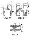
- Figs. 1-3 and 12-14 illustrate the preferred attachment means, a clip 30.
- the clip 30 is divided into a clip clevis 96 and a clip leg portion 98.
- the clip clevis 96 includes a clevis slot 100 adapted to receive the clip portion 64 of the housing base 26 therein.
- the clip clevis 96 further includes a pivot aperture 102 wherein a fastener may be inserted to pivotally affix the clip clevis 96 to the clip portion 64.
- the clip leg portion 98 includes a first leg 104 and a second leg 106 which are spaced to accommodate some part of headgear therebetween to retain the clip 30 on the headgear.
- each of the legs 104 and 106 is furcated by the inclusion of respective peg slots 108 and 110, the purpose of which will be described below.
- the clip 30 may be made of suitable metal, plastic or ceramic materials, and the preferred embodiment of the clip 30 is made of "VALOX" or "NORYL".
- illumination assembly 20 is completed by inserting the clip portion 64 of the housing base 26 within the clevis slot 100 of the clip 30.
- a fastener preferably a screw
- the housing 22 and optical element 24 can move in two degrees of freedom: they can rotate upward and downward about the clip clevis 96, and they can move forward and backward by rotationally telescoping the housing 22 about the plug portion 62 of the housing base 26.
- Figs. 1-3 illustrate the use of the clip 30 to mount the illumination assembly 20 to a binocular telescope and eyeglass system 300 known to the art, a brief description of which is now provided.
- the binocular telescope and eyeglass system 300 includes eyeglasses 316 and binocular telescope 304.
- An exemplary binocular telescope 304 is the "ORASCOPTIC DIMENSION-3" binocular telescope (Orascoptic Research, Inc., Madison, Wisconsin), and the description set forth herein will be made with reference to that binocular telescope, though it is understood that the illumination assembly 20 is not limited to either this binocular telescope or even this type of headgear in general.
- the binocular telescope 304 is attached to the eyeglasses 316 by use of a pivot member 306.
- the pivot member 306 is attached to a bridge 308 which an includes a bridge adjustment knob 310 for adjusting the extension of arms 312 and thus the interpupillary distance of loupes 314.
- the first leg 104 and second leg 106 of the clip 30 may be slipped over the bridge 308 with the peg slot 108 accommodating the bridge adjustment knob 310 therein.
- the illumination assembly 20 may be inverted so that the peg slot 110 accommodates the bridge adjustment knob 310 therein and the housing 22 rests between the loupes 314 to provide direct on-line coaxial illumination.
- the area on the first leg 104 immediately adjacent the peg slot 108 and the area of the second leg 106 immediately adjacent the peg slot 110 each bear a beveled surface 112 to assist in easy insertion of the bridge adjustment knob 310 within either peg slot 108 or 110.
- the light guide 28 may be directed up to the nosebridge of the eyeglasses 316 and directed about the user's head as desired, for example, by taping or clipping the light guide 28 to a rim of the eyeglasses 316 Unlike the illumination devices of the prior art, the illumination assembly 20 is light and small enough that it will not cause the binocular telescopes 300 to tip downward about the pivot member 306, nor will it interfere with the use's binocular vision when coaxially mounted. Additionally, the use of the 2 mm fiberoptic bundle for the light guide 28 provides exceptionally high illumination intensity, but it still allows for easy mounting of the illumination assembly 20 onto binocular telescopes 300 or similar headgear without interfering with the user's vision, comfort, or ease of using the illumination assembly 20.
- the attachment means described above may be replaced by any type of clip, buckle, latch, bracket, hook, loop, fastener, carriage, or similar attachment structure or means known to the art, also including adhesive and magnetic means.
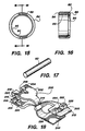
- An example of an alternative embodiment of the attachment means is illustrated by a clip 200 illustrated in Fig. 18.
- the clip has a first member 202 having a jaw 204 and a handle 206, and a second member 208 with a jaw 210 and a handle 212.
- the jaws 204 and 210 are biased into a normally closed position by a spring 214.
- the jaws 204 and 210 are furcated so that they each include a peg slot 216 for receiving the bridge adjustment knob 310 therein.
- the jaws 204 and 210 each include a pair of spaced ridges, a forward ridge 218 and a rear ridge 220.
- the second member 208 includes a clip clevis 222 which defines a clevis slot 224 wherein the clip portion 64 of the housing base 26 may rest.
- the clip clevis 222 further includes a pivot aperture 226 wherein a fastener may be inserted to affix the clip portion 64 to the clip clevis 222.
- the jaws 204 and 210 open so that the jaws may encompass and grasp either the bridge 308 of binocular telescope 304 or the nose eyeglasses 316 in which case the nose bridge may rest between the forward ridges 218 and the rear ridges 220.
- the clip 200 could be attached to the other parts of the binocular telescope 304 or eyeglasses 316 instead, such as to the arms 312 of the binocular telescope 304 or the rim 316 of the eyeglasses 316.
- the clip 200 has spring-biased jaws 204 and 210 which may be adapted to grasp virtually any object, the clip 200 may be affixed not only to the binocular telescope 304 or eyeglasses 316, but also to headbands, face shields, or similar headgear. It is understood that a particular type of attachment means may be rapidly removed from the clip portion 64 of the housing base 26 and replaced with attachment means with different sizes and strengths suitable for attachment to different types of head gear.
- the illumination assembly 20 is provided with illumination from a remote light source known to the art (not shown).
- a remote light source known to the art (not shown).
- An example of such a remote light source is shown in U.S. Patent 4,234,910 to Price .
- the light source used in the preferred embodiment of the illumination assembly 20 is the "FIBER-LITE" model 180 light source manufactured by Dolan-Jenner Industries, Inc. of Lawrence, Massachusetts, with a 150 watt lamp used within.
- Other suitable light sources are the "FIBER-LITE" model 170-D by Dolan-Jenner Industries, Inc. or the model I-150 fiberoptic illumination light source made by Cuda Products Co. of Jacksonville, Florida.
- the light source preferably has a "breakaway" safety release at the attachment terminal where the light guide 28 is attached to the light source so that if the light guide 28 is given a sudden jerk, the terminal will release the light guide 28 rather than causing it to break.
- the remote light source also preferably has such features as a rheostat or similar device for selectively adjusting the illumination intensity to maximise bulb life, 110 arid 220 volt operation capability, and a quiet cooling fan mechanism.
- the light source is located remotely from the illumination assembly 20 and the illumination is piped in via the light guide 28, negligible heat is transferred to the user and/or patient or workpiece.
- the illumination assembly 20 should transmit an undesired amount of infrared or ultraviolet radiation to the illumination assembly 20, the user may attach a filter to the exterior attachment bevel 46 of the housing 22 to filter out these radiation components. This step is helpful where light-cured materials are being worked with at the patient or at the workpiece, such as the light-cured composites used in dentistry.
- the user could introduce a filter or dichroic mirror within the remote light source so that only the desired radiation components of illumination enter the light guide 28. This is helpful where plastic fibre(s) is used in the light guide 28 since plastic fiber can generally withstand less heat.
- the preferred embodiment of the illumination assembly 20 as described above has a spot 4.4cm (13/4 inches) in diameter with an intensity of approximately 30,000 lux, and the housing 22 may be telescoped to provide a spot of 7.0cm (2 3/4 inches) diameter and approximately 24,000 lux. Both of these readings are obtained where the optical element 24 is located approximately 30.5cm (12 inches) from the illuminated object. Since the illumination assembly 20 is actually located between 7.6-10.2cm (3-4 inches) from the user's eyes when it is affixed to telescope binoculars 304 as shown in Figs.
- the user actually achieves a spot size of 4.4-7.0cm (1 3/4 - 2 3/4 inches) in diameter when the user's head is positioned approximately 38.1-40.6cm (15-16 inches) from the patient or workpiece.
- This spot size is well-suited for medical use and ideal for dentistry, as it proves full illumination of an oral cavity.
- the spot is automatically directed to wherever the user is looking, so the user does not need to adjust an overhead light while operating.
- the illumination assembly 20 does not strike or interfere with the user's forehead when the binocular telescope 304 are flipped about the telescope pivot 306 into a position parallel to the user's forehead. Since the illumination assembly 20 weighs only 8-10 grams versus 35-40 grams for similar illumination assemblies on the market, the user is for all practical purposes unable to notice the presence of the illumination assembly 20 on the user's head on account of its weight
- the illumination assembly 20 is far more versatile than the prior art illumination assemblies. It can easily be removed and reattached to different parts of headgear if the user finds it desirable to do so. For example, if the user wishes to wear a transparent face shield or safety goggles over a pair of eyeglasses, the illumination assembly 20 can be detached from the eyeglasses and remounted on the face shield or safety goggles.
- the illumination assembly 20 is not limited to the particular arrangement of parts and/or construction described above, but embraces such modified forms thereof that come within the scope of the following claims.
- a unitary housing could be used in place of the housing 22 and the housing base 26.
- different telescoping or telescopically rotating fastening arrangements between the housing 22 and the housing base 26 which do not use the retainer ring 82 and pin 92 arrangement are possible.
- the housing 22 may simply act as a sleeve and telescopically slide over the housing base 26.
- internal threading may be included within the rear cylindrical portion 32 of the housing 22 and complimentary exterior threading may be included on the plug portion 62 of the housing base 26.
- the arrangement described previously is preferred because it prevents the housing 22 from possibly detaching or unscrewing from the plug portion 62 of the housing base 26 and falling onto the patient or workpiece.
- optical element 24 is generally contemplated to be a glass or plastic refractive lens, it need not necessarily be such a lens.
- the optical element 24 could instead be any other type of optical element with positive properties. Examples of such optical elements are binary optic means or a holographic optical element, which function on the basis of diffraction rather than refraction. Another possibility is a gradient index optical element wherein the index of refraction of the element varies linearly or radially about the optical axis to provide the desired optical characteristics.
Landscapes
- Physics & Mathematics (AREA)
- General Physics & Mathematics (AREA)
- Optics & Photonics (AREA)
- Health & Medical Sciences (AREA)
- Ophthalmology & Optometry (AREA)
- Engineering & Computer Science (AREA)
- General Engineering & Computer Science (AREA)
- General Health & Medical Sciences (AREA)
- Telescopes (AREA)
- Dental Tools And Instruments Or Auxiliary Dental Instruments (AREA)
- Non-Portable Lighting Devices Or Systems Thereof (AREA)
- Endoscopes (AREA)
Abstract
Description
- The invention relates generally to the field of head-mounted illumination devices for medical and dental use, and specifically to the field of small, lightweight, high intensity illumination assemblies for medical and dental use which are mounted on the user's head to provide coaxial illumination. Such an assembly is disclosed in US-A-3285242.
- Personnel who work in medical and dental fields frequently have a need to illuminate a portion of a patient or workpiece. At the same time, they require the free use of their hands. Both of these needs are met by illumination assemblies known to the art which are mounted on the user's head or headgear and which illuminate the patient the patient or workpiece. An example of such an apparatus can be found in US Patent 5,341,513 to Klein et al., which describes a headband whereupon a lamp is mounted.
- However, there are certain characteristics which are desirable in head-mounted illumination assemblies and which the devices of the prior art fail to either partially or entirely include.
- First, the illumination beam supplied by the illumination assembly should correspond as closely as possible to the user's line of vision, i.e., the illumination assembly should illuminate the patient or workpiece from a point as close to the user's eyes as possible (preferably from immediately between the eyes). Otherwise, the user's hands, arms, or any other objects may obstruct the light path and cast shadows upon the patient or workpiece. Also, dentists and medical personnel often have a need to look into very small holes, such as holes drilled into teeth, and the interior of such holes generally cannot be viewed without direct illumination along the axis of the hole. If the illumination source is mounted near the user's eyes and emits a beam of illumination which is parallel to and very nearly coaxial with the user's line of sight, the chances for the creation of shadows is minimised. Additionally, such a mounting position ensures that the user will automatically illuminate any area that the user views provided the user's head is directed toward that area.
- Second, the illumination assembly should be safe and comfortable to wear. Some prior art devices include light sources mounted on a user's head or headgear, such as those of U.S. Patent 3,350,552 to Lawrence and U.S. Patent 5,341,513 to Klein et al, which respectively illustrate lamps mounted to eyeglasses and a headband. These devices have proven to be disadvantageous in that they can create a great deal of heat at a point close to the user's head, especially if high-intensity lightbulbs are used. These devices can therefore be intensely uncomfortable to wear because they cause hot air to rise into the user's face when the user looks down, they cause perspiration from the user's forehead to drip into the user's eyes (and onto the patient or workpiece), and they can even cause burns to the user or patient when they grow hot enough. Because the prior art illumination assemblies which mount a light source directly to the user's head are so uncomfortable, many devices instead use a light guide to transmit light from a remotely-located light source. Examples of such devices are illustrated in U.S. Patent 3,285,242 to Wallace, U.S. Patent 4,234,910 to Price, U.S. Patents 3,951,139 and 4,104,709 to Kloots, U.S. Patent 4,797,736 to Kloots et al, and U.S. Patent 5,331,357 to Cooley et al.
- Third, the illumination assembly should be capable of use on different parts of the user's head, and should also be capable of being adjustably positioned to illuminate different desired areas. Many of the prior art illumination assemblies are not very versatile because they are permanently mounted within already existing headgear, such as the illumination devices of Cooley et al. and Price, which show eyeglasses with illumination elements at opposing sides of the eyeglass frames adjacent the support legs. These devices can neither be used without the associated headgear nor repositioned to illuminate different areas of the patient or workpiece. Additionally, if an illumination assembly is permanently affixed to headgear such as eyeglasses, headbands, face shields, etc., it is often difficult to use a second type of headgear in conjunction with the first type of headgear and the illumination assembly. For example, a face shield can either scatter or entirely obstruct the light emitted from the devices of Price and Cooley et al.
- Fourth, since the illumination assembly may become contaminated with particles from the patient or workpiece or fluids splashing therefrom, the illumination assembly should be easy to clean.
- Fifth, the illumination assembly should produce an illuminated spot of high and uniform intensity. A small, bright spot is extremely important to most medical and dental applications, such as when the interior of a cavity must be viewed (e.g., the interior of a hole drilled within a tooth). In that case, full illumination of the cavity is desired with minimum illumination of the surrounding area outside the cavity. Ideally, the spot size should also be variable in order to allow the user to tailor the spot size to fit the area to be illuminated. U.S. Patent 4,104,709 to Kloots describes an illumination device which provides a continuously variable spot size, as does U.S. Patent 3,285,242 to Wallace.
- Sixth, the weight of the illumination assembly should be small enough that the headgear does not dig into the user's head and so that the user is virtually unaware of its presence on the user's head. The prior art illumination assemblies tend to be quite heavy due to their use of several optical elements (lenses, prisms, mirrors, etc.) and means for mounting these optical elements within the illumination assembly. The several optical elements are required in order to produce a properly sized, well-defined, uniform spot, especially in the illumination assemblies which allow for a variable spot size (e.g., the aforementioned patent to Wallace and U.S. Patent 4,104,709 to Kloots). Because the optical elements must generally be made of heavy, high-grade refractive glass to decrease their size and increase their optical quality, the optical elements comprise a substantial percentage of the illumination assembly's overall weight. Due to the weight of the glass, the addition of even a single additional optical element tends to dramatically increase the weight of an illumination assembly. Additionally, while the art is beginning to develop plastic lenses of high optical quality and lighter weight than glass lenses, these lenses are not preferred for use at exposed portions of the illumination assembly because they are more easily scratched, scuffed, or otherwise damaged during cleaning.
- The weight of the illumination assembly can also create greater problems than discomfort. It can make a substantial difference in its operability and safety of use, since a heavy illumination assembly can cause headgear to shift or even fall off the head. For example, if the prior art illumination assemblies were attached to lenses, loupes, or telescopic binoculars used in association with eyeglasses, such as "ORASCOPTIC DIMENSION-3" telescopic binoculars (Orascoptic Research, Inc. of Madison, Wisconsin), they would cause the binoculars to relocate downward rather than staying focused at the height the user desires. This can be disastrous where the user's hands are performing an important medical procedure since the user may be forced to interrupt the procedure to readjust the binoculars, or else simply proceed and perform the procedure with impaired vision. As another example, when the prior art illumination assemblies are mounted to eyeglasses, they tend to pull the eyeglasses off of the user's head if he or she looks downward. Obviously, the user would prefer not to have the illumination assembly and its associated headgear fall upon or within the operating area on the patient or workpiece.
- Seventh, the illumination assembly should be as small as possible to increase its ease of use and to prevent interference with the user's binocular or peripheral vision. Many of the prior art illumination assemblies have a large and awkward size, either due to their incorporation of internal illumination sources directly within the assembly or due to the requirements of the optics within the assembly. This is especially true of the aforementioned illumination assemblies which provide variable spot size. Also, large illumination assemblies interfere with the user's binocular vision when mounted coaxially between the user's eyes.
- The prior art illumination assemblies are also difficult to use when mounted coaxially, or when mounted to headgear in general, due to their use of bulky and heavy electrical or light guide cords. These cords can bind and inhibit repositioning of illumination assemblies due to the stiffness of the cords, and they can also interfere with the user's binocular or peripheral vision. Thick and heavy cords are also uncomfortable to wear when draped over or about the user's head, and they contribute to a feeling that the user is bound or "leashed" to the power supply or remote illumination source. While the prior art illustrates smaller, lighter cords for supplying power or illumination to illumination assemblies, the smaller and lighter cords have the drawback that they cannot bear as much power or illumination to the illumination assemblies. Thus, if the user wishes to obtain the advantages of a smaller cord, he or she is generally forced to settle for less illumination.
- In summary, the prior art does not include an illumination assembly which provides a sufficiently small and intense variable spot size while at the same time providing a versatile illumination assembly which is small and lightweight enough that it can be attached to various forms of headgear. In particular, the prior art does not include an illumination assembly as described above suitable for attachment to and use with eyeglasses, headbands, or face shields in accompaniment with lenses, loupes, or binoculars associated with the eyeglasses, headbands, or face shields.
- US-A-3285242 mentioned above discloses an illumination assembly comprising a light guide having an output end and an input end, the input end being adapted for connection to a remote illumination source; a housing having a light guide opening and an illumination opening, the output end of the light guide extending within the housing and being aligned to illuminate the illumination opening; optical means mounted within the illumination opening of the housing; and attachment means for removably attaching the housing to headgear.
- A first aspect of the present invention is characterised in that the optical means comprise a single optical element.
- According to a second aspect of the present invention, there is provided the combination of.the illumination assembly according to the first aspect and eye glasses, wherein the attachment means is removably attached to the eyeglasses.
- According to a third aspect of the present invention, there is provided the combination of the illumination assembly according to the first aspect and binocular telescopes, wherein the attachment means is removably attached to the binocular telescopes.
- In preferred embodiments of the present invention, the illumination assembly uses a remote illumination source and transmits the illumination to the illumination assembly by use of a lightweight flexible light guide, such as a fiberoptic bundle, and therefore avoids heating the user's head or excessively weighting the user's head. The housing of the illumination assembly may be adjusted to alter the distance between the light guide and the optical element and thereby provide a variable size illuminated spot of high and uniform intensity.
- In preferred embodiments of the present invention, the illumination assembly utilizes a single optical element in place of the multiple optical elements found in the prior art. The optical element for use within the illumination assembly is contemplated to be an positive focal length refractive lens, more particularly an aspheric condensing lens having a planar face and an aspheric face wherein the aspheric face is directed toward the light guide. This lens has been found to work admirably well in place of multiple optical elements.
- Versatile attachment means for removably attaching the illumination assembly to the user's headgear (e.g., face shields, headbands, and eyeglasses, and associated lenses, loupes, and binoculars) allow the illumination assembly to be quickly fit to a wide variety of different types of headgear. The attachment means allows mounting of the illumination assembly in a position between the eyes of the user to provide coaxial in-line shadowless illumination of the operating site, and to automatically illuminate the area the user is viewing.
- The illumination assembly is small, having a maximum dimension of approximately 4.6cm (1.8 inches) without the attachment means and light guide, or approximately 4.1cm (1.6 inches) when the housing is telescopically reduced to a minimum length. By using only a single glass optical element within the housing and by remotely locating the illuminating source, the weight of the illumination assembly is substantially reduced when compared to the illumination assemblies of the prior art. The weight is further reduced because there is no need for the heavy ceramic potting or reflective means that are required when the illumination source is located within the illumination assembly, and because a light guide having a small diameter is used. The weight of the illumination assembly without the attachment means and light guide is only approximately 8-10 grams when a plastic housing is used.
- Due to its low weight, the illumination assembly is ideal for use with headgear such as face shields, headbands, and eyeglasses, and associated devices such as lenses, loupes, and binoculars, since it will not cause the headgear or associated devices to shift or fall from the user's head. Additionally, the illumination assembly is small enough in both diameter and length that it does not interfere with the user's binocular vision when mounted coaxially; it is virtually invisible to the user when mounted between the eyes. The light guide is small enough that it is unseen and virtually unfelt by the user, and its weight and stiffness will not cause the illumination assembly to inadvertently readjust or reposition against the user's wishes. Despite the small size of the light guide, its use does not decrease the illumination of the illumination assembly due to the high efficiency of the remainder of the assembly.
- Further advantages, features, and objects of the invention will be apparent from the following detailed description of the invention in conjunction with the associated drawings.
-
- Fig. 1 is a perspective view of the illumination assembly of the present invention shown mounted on a pair of telescopic binoculars affixed to a pair of eyeglasses.
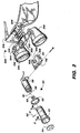
- Fig. 2 is an exploded perspective view of the illumination assembly of Fig. 1.
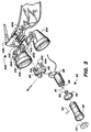
- Fig. 3 is an exploded perspective view of the illumination assembly of Fig. 1 situated in an alternate position.
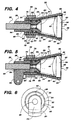
- Fig. 4 is a top plan view of the illumination assembly shown without the attachment means.
- Fig. 5 is a side elevated view of the illumination assembly shown without the attachment means.
- Fig. 6 is a rear elevated view of the illumination assembly shown without the attachment means.
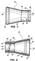
- Fig. 7 is a side elevated view of the housing of the illumination assembly.
- Fig. 8 is a side cross-sectional view of the housing of the illumination assembly taken along line 8-8 of Fig. 3.
- Fig. 9 is a side elevated view of the housing base of the illumination assembly.
- Fig. 10 is a top plan view of the housing base of the illumination assembly.
- Fig. 11 is a side cross-sectional view of the housing base of the illumination assembly taken along lines 11-11 of Fig. 10.
- Fig. 12 is a side elevated view of the preferred attachment means of the illumination assembly.
- Fig. 13 is a top plan view of the preferred attachment means of the illumination assembly.
- Fig. 14 is a rear elevated view of the preferred attachment means of the illumination assembly.
- Fig. 15 is a front elevated view of the retainer ring of the illumination assembly.
- Fig. 16 is a side cross-sectional view of the retainer ring of the illumination assembly taken along line 16-16 of Fig. 15.
- Fig. 17 is a perspective view of the pin of the illumination assembly.
- Fig. 18 is a perspective view of an alternative attachment means for the illumination assembly.
-
- In the drawings, wherein the same or similar features are designated throughout with the same reference numeral, the illumination assembly of the present invention is shown at 20 in Figs. 1-3. The
illumination assembly 20 has five main components: ahousing 22 which contains anoptical element 24, ahousing base 26 engaged to thehousing 22 and wherein alight guide 28 enters, and aclip 30 which provides attachment means for removably attaching thehousing base 26 to the user's head or headgear. Throughout this specification, when reference is made to attachment of theillumination assembly 20 to the user's head or headgear, this is understood to include attachment to implements mounted on the user's head such as eyeglasses and goggles, face shields and masks, and headbands and helmets, as well as similar implements. It is further understood to include attachment to accessory implements such as lenses, loupes, and binoculars mounted on the aforementioned implements. Each of the components of theillumination assembly 20 will be discussed in turn. - Figs. 4-8, and particularly Figs. 7-8, best illustrate the
housing 22. Thehousing 22 has a rearcylindrical portion 32 and a forwardfrustoconical portion 34. The forwardfrustoconical portion 34 includes aninterior surface 36 having arim 38 which defines anillumination opening 39. Aninterior bevel 40 is included on theinterior surface 36 near therim 38 so that theoptical element 24 may be received therein and affixed in snap-fit relation, by staking or adhesives, or by other affixment means known to the art. The forwardfrustoconical portion 34 additionally includes anexterior attachment bevel 46 whereupon filters may be attached in snap-fit fashion if desired. Other modes of filter attachment, such as threaded attachment, may be used by configuring theexterior attachment bevel 46 accordingly. - The rear
cylindrical portion 32 of thehousing 22 has arear end 48, acircumferential engagement slot 50 located near therear end 48, and apin slot 52 on itsinterior surface 54. The purposes of these features will be described shortly. Thepin slot 52 is preferably formed by drilling anentry hole 56 on theexterior surface 58 of the rearcylindrical portion 32 and extending the drill until it emerges on theinterior surface 54, and further extending the drill so it exits through anexit hole 60 back to theexterior surface 58. - In the preferred embodiment of the
illumination assembly 20, the maximum diameter of the forwardfrustoconical portion 34 is approximately 2.0cm (0.78 inches) and the diameter of the rearcylindrical portion 32 is approximately 1.2cm (0.47 inches). This small diameter is especially helpful in avoiding interference with the user's binocular vision. The distance between the rearcylindrical portion 32 and theinterior bevel 40 is approximately 1.2cm (0.47 inches). Thehousing 22 has an overall length of approximately 3.2cm (1.26 inches). Thehousing 22 is made of "VALOX" or "NORYL" (General Electric, Inc.,, New York, NY), though other plastic, metal, or ceramic substances could be used. - The
optical element 24, which is shown best in Figs. 4 and 5, is preferably a refractive lens having a positive focal length, i.e., a positive lens. Such a lens collects illumination from within thehousing 22 and projects it to an area in front of thehousing 22. While a plano-convex lens could be used for theoptical element 24, superior results (i.e. better spot size and intensity with a smaller and lighter lens) have been found to occur with the use of an aspherical lens having acurved surface 42 and an opposingplanar surface 44. The preferredoptical element 24 is the No. 17.1025 aspheric condensing lens manufactured by Rolyn Optics Company of Covina, California, which has an 18 mm diameter, a center thickness of 7.4 mm, an edge thickness of 3.3 mm, a focal length of 15 mm, and a back focal length of 10.1 mm. - The
optical element 24 is mounted within theinterior bevel 40 with itscurved surface 42 adjacent theinterior surface 36 of the forwardfrustoconical portion 34 of thehousing 22, and withplanar surface 44 facing outward to provide a flat surface for cleaning purposes. Some prior art illumination assemblies have the disadvantage that they use an exposed curved lens surface, and matter can splash from the operating surface onto the lens surface and collect either on the face of the lens or in the corners where the lens is joined to the housing. The matter would then dry and firmly adhere to the lens surface, especially in those illumination assemblies wherein the lens surface was subject to heating from the illumination source. The matter would become extremely difficult to clean off without scrubbing, and scrubbing sometimes causes scratches in the lens and gradual degradation of the illumination quality. The exposedplanar surface 44 does not provide a concave lens surface wherein matter can adhere, nor does it provide the tight corner between theoptical element 24 and thehousing 22 that a convex lens surface provides. - The
housing base 26 is illustrated in detail in Pigs. 9-11. Thehousing base 26 has two main portions, aplug portion 62 and aclip portion 64, with alight guide channel 66 running through both portions. Theplug portion 62 includes ahead 68, aneck 70, and abody 72, and is adapted to fit closely within the rearcylindrical portion 32 of thehousing 22. As best shown by Fig. 11, thelight guide channel 66 includes a light guide opening in thebody 72 wherein thelight guide 28 enters, and tapered and threadedportions head 68 adapted to receive a threaded end terminator on thelight guide 28. Thebody 72 contains ahelical groove 78, the purpose of which will be explained shortly. - The
clip portion 64 of thehousing base 26 is adapted to be fastened to attachment means so that thehousing base 26 and the associatedhousing 22 may be affixed to the user's headgear. Thus, theclip portion 64 is substantially flattened and includes apin aperture 80, and is therefore ideally suited for insertion within and attachment to a clevis, as will be discussed below. - In the preferred embodiment of the
illumination assembly 20, thehousing base 26 has an overall length of approximately 2.5cm (1 inch), of which theclip portion 64 occupies approximately 0.9cm (0.34 inches). Thehousing base 26 is made of "VALOX" or "NORYL", though other plastic, metal, or ceramic substances could be used. - The
light guide 28 has an input end (not shown) for connection to a remote light source, and also an output end 81 (Fig 2) which bears a threaded end terminator known to the art, e.g., a 6-32 screw thread end terminator. Thelight guide 28 may be any type of light guide known to the art, such as singular or bundled plastic or glass fiberoptic cables or liquid-filled light guides. The preferred embodiment of theillumination assembly 20 utilizes a bundle of serveral glass fiberoptic cables with a total optical transmission diameter of 2 mm and a numerical aperture greater than or equal to 0.5. Exemplary fiberoptic cable is manufactered by Dolan-Jenner Industries, Inc. of Lawrence, Massachusetts, and also by Fiberoptic Systems, Inc. of Simi Valley California. Exemplary liquid-filled light guides are made by Electro-Lite Corp. of Danbury, Connecticut and Oriel Corp. of Stratford, Connecticut. Regardless of how many fibers are chosen for the fiberoptic bundle nor what the optical transmission diameter of thelight guide 28 is to be, the use of multiple fibers is recommended because it reduces the potential for breakage of thelight guide 28 as compared to the prior art single-fiber illumination assemblies. A 2 mm or smaller light guide is preferred because larger light guides are heavy, clumsy , and difficult to affix to certain headgear (e.g. to glasses) and to drape about the user's head, and they further tend to be so heavy and stiff that they interfere with fine positioning of theillumination assembly 20 or cause theillumination assembly 20 to inadvertently reposition during use. - The
illumination assembly 20 is shown in assembled form in Figs. 4-6 without the attachment means. Apart from thehousing 22,optical element 24,housing base 26, andlight guide 28, three additional components are recommended for inclusion within this portion of theillumination assembly 20. The first component is a retainer ring 82 (Fig 16). Theretainer ring 82 is a frustoconial ring having afront rim 84, arear rim 86, and aninterior surface 88. Theretainer ring 82 includes alip 90 protruding radially inward from theinterior surface 88 at thefront rim 86. Theretainer ring 82 is preferably made of a flexible resilient material which can be slightly deformed without breaking, and which will generally tend to revert to its original shape after deformation. In the preferred embodiment of the invention, theretainer ring 82 is made out of "VALOX" or "NORYL." The second component is a pin 92 (Fig.2), which is a small rod-like member which is preferably made of metal, such as stainless steel. The third component is an O-ring 93 made of silicone rubber or a similar flexible high-friction substance, and which is adapted to fit within theneck 70 of thehousing base 26. - To assemble the portion of the
illumination assembly 20 illustrated in Figs.4-6, theoptical element 24 is inserted within theinterior bevel 40 and affixed therein by staking the rim 38 (as shown in Figs 4 and 5 by means of heat, ultrasound, or other means. Alternatively, theoptical element 24 may simply be glued to into theinterior bevel 40 by use of adhesives known to the art. Thelight guide 28 is inserted within thelight guide channel 66 of thehousing base 26, and its end terminator is attached to thehead 68 of thehousing base 26 within thelight guide channel 66. As noted earlier and as shown in Figs. 4-5 and 9-11, the taperedportion 74 and threadedportion 76 of thelight guide channel 66 are adapted to receive a threaded end terminator. The O-ring 93 is slipped over theplug portion 62 of thehousing base 26 until it rests within theneck 70. Theretainer ring 82 is slipped over theplug portion 62 of thehousing base 26 with therear rim 86 first. Thehousing 22 is then slipped over theplug portion 62 of thehousing base 26 so that theplug portion 62 rests within the rearcylindrical portion 32 of thehousing 22. Thehelical groove 78 in theplug portion 62 of thehousing base 26 is aligned with thepin slot 52 on theinterior surface 54 of the rearcylindrical portion 32. Thepin 92 is inserted within theentry hole 56 to engage both thepin slot 52 andhelical groove 78. When thepin 92 is fully inserted within thepin slot 52, it extends from theentry hole 56 to theexit hole 60 without protruding from theexterior surface 58 of the rearcylindrical portion 32. Theretainer ring 82 is then slid forward on the rearcylindrical portion 32 of thehousing 22 until thelip 90 engages theengagement slot 50. When this is done, theinterior surface 88 of theretainer ring 82 holds thepin 92 within thepin slot 52 and prevents it from falling out of the entry or exit holes 56 and 60. - When the
housing 22,housing base 26,retainer ring 82 andpin 92 are assembled in the arrangement described above and as shown in Figs. 4-6, thehousing 22 may be rotationally telescoped in relation to thehousing base 26 due to the action of thepin 92 within thehelical groove 78. As can be seen in Figs. 4 and 5, this telescopic adjustment alters the distance between theoptical element 24 and the terminal end of thelight guide 28, and therefore provides for adjustment of the spot size. The O-ring 93 provides frictional means for preventing unwanted telescopic rotation of thehousing 22, and it also prevents moisture from entering thehousing 22. - Attachment means for removably attaching the
illumination assembly 20 to headgear may then be mounted to theclip portion 64 of thehousing base 26 to form the completedillumination assembly 20. - Figs. 1-3 and 12-14 illustrate the preferred attachment means, a
clip 30. Theclip 30 is divided into aclip clevis 96 and aclip leg portion 98. Theclip clevis 96 includes aclevis slot 100 adapted to receive theclip portion 64 of thehousing base 26 therein. Theclip clevis 96 further includes apivot aperture 102 wherein a fastener may be inserted to pivotally affix theclip clevis 96 to theclip portion 64. Theclip leg portion 98 includes afirst leg 104 and asecond leg 106 which are spaced to accommodate some part of headgear therebetween to retain theclip 30 on the headgear. In theclip 30, each of thelegs respective peg slots clip 30 may be made of suitable metal, plastic or ceramic materials, and the preferred embodiment of theclip 30 is made of "VALOX" or "NORYL". - The construction of
illumination assembly 20 is completed by inserting theclip portion 64 of thehousing base 26 within theclevis slot 100 of theclip 30. A fastener (preferably a screw) is inserted through thepivot aperture 102 to pivotably affix the two parts together. When fully assembled, thehousing 22 andoptical element 24 can move in two degrees of freedom: they can rotate upward and downward about theclip clevis 96, and they can move forward and backward by rotationally telescoping thehousing 22 about theplug portion 62 of thehousing base 26. - Figs. 1-3 illustrate the use of the
clip 30 to mount theillumination assembly 20 to a binocular telescope andeyeglass system 300 known to the art, a brief description of which is now provided. The binocular telescope andeyeglass system 300 includeseyeglasses 316 andbinocular telescope 304. An exemplarybinocular telescope 304 is the "ORASCOPTIC DIMENSION-3" binocular telescope (Orascoptic Research, Inc., Madison, Wisconsin), and the description set forth herein will be made with reference to that binocular telescope, though it is understood that theillumination assembly 20 is not limited to either this binocular telescope or even this type of headgear in general. Thebinocular telescope 304 is attached to theeyeglasses 316 by use of apivot member 306. Thepivot member 306 is attached to abridge 308 which an includes abridge adjustment knob 310 for adjusting the extension ofarms 312 and thus the interpupillary distance ofloupes 314. - As shown in Figs. 1 and 2, the
first leg 104 andsecond leg 106 of theclip 30 may be slipped over thebridge 308 with thepeg slot 108 accommodating thebridge adjustment knob 310 therein. Alternatively, as shown in Fig. 3, theillumination assembly 20 may be inverted so that thepeg slot 110 accommodates thebridge adjustment knob 310 therein and thehousing 22 rests between theloupes 314 to provide direct on-line coaxial illumination. Preferably, the area on thefirst leg 104 immediately adjacent thepeg slot 108 and the area of thesecond leg 106 immediately adjacent thepeg slot 110 each bear abeveled surface 112 to assist in easy insertion of thebridge adjustment knob 310 within eitherpeg slot light guide 28 may be directed up to the nosebridge of theeyeglasses 316 and directed about the user's head as desired, for example, by taping or clipping thelight guide 28 to a rim of theeyeglasses 316 Unlike the illumination devices of the prior art, theillumination assembly 20 is light and small enough that it will not cause thebinocular telescopes 300 to tip downward about thepivot member 306, nor will it interfere with the use's binocular vision when coaxially mounted. Additionally, the use of the 2 mm fiberoptic bundle for thelight guide 28 provides exceptionally high illumination intensity, but it still allows for easy mounting of theillumination assembly 20 ontobinocular telescopes 300 or similar headgear without interfering with the user's vision, comfort, or ease of using theillumination assembly 20. - The attachment means described above may be replaced by any type of clip, buckle, latch, bracket, hook, loop, fastener, carriage, or similar attachment structure or means known to the art, also including adhesive and magnetic means. An example of an alternative embodiment of the attachment means is illustrated by a
clip 200 illustrated in Fig. 18. The clip has afirst member 202 having ajaw 204 and ahandle 206, and asecond member 208 with ajaw 210 and ahandle 212. Thejaws spring 214. Thejaws peg slot 216 for receiving thebridge adjustment knob 310 therein. Additionally, thejaws forward ridge 218 and arear ridge 220. Thesecond member 208 includes aclip clevis 222 which defines aclevis slot 224 wherein theclip portion 64 of thehousing base 26 may rest. Theclip clevis 222 further includes apivot aperture 226 wherein a fastener may be inserted to affix theclip portion 64 to theclip clevis 222. - By pressing together the
handles jaws bridge 308 ofbinocular telescope 304 or thenose eyeglasses 316 in which case the nose bridge may rest between theforward ridges 218 and therear ridges 220. Alternatively, theclip 200 could be attached to the other parts of thebinocular telescope 304 oreyeglasses 316 instead, such as to thearms 312 of thebinocular telescope 304 or therim 316 of theeyeglasses 316. Because theclip 200 has spring-biasedjaws clip 200 may be affixed not only to thebinocular telescope 304 oreyeglasses 316, but also to headbands, face shields, or similar headgear. It is understood that a particular type of attachment means may be rapidly removed from theclip portion 64 of thehousing base 26 and replaced with attachment means with different sizes and strengths suitable for attachment to different types of head gear. - The
illumination assembly 20 is provided with illumination from a remote light source known to the art (not shown). An example of such a remote light source is shown in U.S. Patent 4,234,910 to Price. The light source used in the preferred embodiment of theillumination assembly 20 is the "FIBER-LITE" model 180 light source manufactured by Dolan-Jenner Industries, Inc. of Lawrence, Massachusetts, with a 150 watt lamp used within. Other suitable light sources are the "FIBER-LITE" model 170-D by Dolan-Jenner Industries, Inc. or the model I-150 fiberoptic illumination light source made by Cuda Products Co. of Jacksonville, Florida. The light source preferably has a "breakaway" safety release at the attachment terminal where thelight guide 28 is attached to the light source so that if thelight guide 28 is given a sudden jerk, the terminal will release thelight guide 28 rather than causing it to break. The remote light source also preferably has such features as a rheostat or similar device for selectively adjusting the illumination intensity to maximise bulb life, 110 arid 220 volt operation capability, and a quiet cooling fan mechanism. - Because the light source is located remotely from the
illumination assembly 20 and the illumination is piped in via thelight guide 28, negligible heat is transferred to the user and/or patient or workpiece. If theillumination assembly 20 should transmit an undesired amount of infrared or ultraviolet radiation to theillumination assembly 20, the user may attach a filter to theexterior attachment bevel 46 of thehousing 22 to filter out these radiation components. This step is helpful where light-cured materials are being worked with at the patient or at the workpiece, such as the light-cured composites used in dentistry. Alternatively (or additionally), the user could introduce a filter or dichroic mirror within the remote light source so that only the desired radiation components of illumination enter thelight guide 28. This is helpful where plastic fibre(s) is used in thelight guide 28 since plastic fiber can generally withstand less heat. - The preferred embodiment of the
illumination assembly 20 as described above has a spot 4.4cm (13/4 inches) in diameter with an intensity of approximately 30,000 lux, and thehousing 22 may be telescoped to provide a spot of 7.0cm (2 3/4 inches) diameter and approximately 24,000 lux. Both of these readings are obtained where theoptical element 24 is located approximately 30.5cm (12 inches) from the illuminated object. Since theillumination assembly 20 is actually located between 7.6-10.2cm (3-4 inches) from the user's eyes when it is affixed totelescope binoculars 304 as shown in Figs. 1-3, the user actually achieves a spot size of 4.4-7.0cm (1 3/4 - 2 3/4 inches) in diameter when the user's head is positioned approximately 38.1-40.6cm (15-16 inches) from the patient or workpiece. This spot size is well-suited for medical use and ideal for dentistry, as it proves full illumination of an oral cavity. There is negligible scattered light or stray light outside of the illuminated spot, and the illumination within the spot is only slightly center-weighted with minimal blurring at the spot edges. The spot is automatically directed to wherever the user is looking, so the user does not need to adjust an overhead light while operating. - Due to its small size, the
illumination assembly 20 does not strike or interfere with the user's forehead when thebinocular telescope 304 are flipped about thetelescope pivot 306 into a position parallel to the user's forehead. Since theillumination assembly 20 weighs only 8-10 grams versus 35-40 grams for similar illumination assemblies on the market, the user is for all practical purposes unable to notice the presence of theillumination assembly 20 on the user's head on account of its weight - Owing to the small size and weight of the
illumination assembly 20 and its use of theclip 30, theillumination assembly 20 is far more versatile than the prior art illumination assemblies. It can easily be removed and reattached to different parts of headgear if the user finds it desirable to do so. For example, if the user wishes to wear a transparent face shield or safety goggles over a pair of eyeglasses, theillumination assembly 20 can be detached from the eyeglasses and remounted on the face shield or safety goggles. - It is understood that the
illumination assembly 20 is not limited to the particular arrangement of parts and/or construction described above, but embraces such modified forms thereof that come within the scope of the following claims. For example, it is understood that a unitary housing could be used in place of thehousing 22 and thehousing base 26. It is also understood that different telescoping or telescopically rotating fastening arrangements between thehousing 22 and thehousing base 26 which do not use theretainer ring 82 andpin 92 arrangement are possible. For example, thehousing 22 may simply act as a sleeve and telescopically slide over thehousing base 26. Alternatively, internal threading may be included within the rearcylindrical portion 32 of thehousing 22 and complimentary exterior threading may be included on theplug portion 62 of thehousing base 26. However, the arrangement described previously is preferred because it prevents thehousing 22 from possibly detaching or unscrewing from theplug portion 62 of thehousing base 26 and falling onto the patient or workpiece. - Additionally, while the
optical element 24 is generally contemplated to be a glass or plastic refractive lens, it need not necessarily be such a lens. Theoptical element 24 could instead be any other type of optical element with positive properties. Examples of such optical elements are binary optic means or a holographic optical element, which function on the basis of diffraction rather than refraction. Another possibility is a gradient index optical element wherein the index of refraction of the element varies linearly or radially about the optical axis to provide the desired optical characteristics.
Claims (11)
- An illumination assembly (20) comprising:(a) a light guide (28) having an output end and an input end, the input end being adapted for connection to a remote illumination source;(b) a housing (22) having a light guide opening and an illumination opening, the output end of the light guide extending within the housing and being aligned to illuminate the illumination opening;(c) optical means (24) mounted within the illumination opening of the housing; and(d) attachment means (30) for removably attaching the housing to headgear, characterised in that said optical means comprises a single optical element (24).
- The illumination assembly (20) of claim 1 wherein the optical element (24) has a curved face and an opposing generally planar face.
- The illumination assembly (20) of claim 2 wherein the curved face faces the output end of the light guide.
- The illumination assembly (20) of any of the preceding claims wherein the light guide (28) is a fiberoptic bundle.
- The illumination assembly (20) of any of the preceding claims wherein the optical element (24) has a diameter of less than approximately 2 centimeters.
- The illumination assembly (20) of any of the preceding claims wherein the illumination assembly has a mass of less than 10 grams.
- The illumination assembly (20) of any of the preceding claims wherein the housing includes an attachment bevel (46) surrounding the illumination opening.
- The illumination assembly (20) of any of the preceding claims wherein the housing (22) includes a main housing body and a housing base (26) adjustably engaged to the main housing body, the housing base including the light guide opening and the main housing body including the illumination opening.
- The illumination assembly (20) of claim 8 wherein a pin (92) is located between and rotatably engaging the main housing body and the housing base.
- The combination of an illumination assembly (20) of any of the preceding claims and eyeglasses (316), wherein the attachment means is removably attached to the eyeglasses.
- The combination of an illumination assembly of any of claims 1 to 9 and binocular telescopes (304), wherein the attachment means is removably attached to the binocular telescopes.
Applications Claiming Priority (3)
| Application Number | Priority Date | Filing Date | Title |
|---|---|---|---|
| US08/447,357 US5667291A (en) | 1995-05-23 | 1995-05-23 | Illumination assembly for dental and medical applications |
| US447357 | 1995-05-23 | ||
| PCT/US1996/007512 WO1996037730A1 (en) | 1995-05-23 | 1996-05-23 | Illumination assembly for dental and medical applications |
Publications (3)
| Publication Number | Publication Date |
|---|---|
| EP0830541A1 EP0830541A1 (en) | 1998-03-25 |
| EP0830541A4 EP0830541A4 (en) | 1998-07-01 |
| EP0830541B1 true EP0830541B1 (en) | 2003-02-19 |
Family
ID=23776052
Family Applications (1)
| Application Number | Title | Priority Date | Filing Date |
|---|---|---|---|
| EP96920423A Expired - Lifetime EP0830541B1 (en) | 1995-05-23 | 1996-05-23 | Illumination assembly for dental and medical applications |
Country Status (7)
| Country | Link |
|---|---|
| US (2) | US5667291A (en) |
| EP (1) | EP0830541B1 (en) |
| AT (1) | ATE232947T1 (en) |
| AU (1) | AU693700B2 (en) |
| CA (1) | CA2217172C (en) |
| DE (1) | DE69626283T2 (en) |
| WO (1) | WO1996037730A1 (en) |
Cited By (1)
| Publication number | Priority date | Publication date | Assignee | Title |
|---|---|---|---|---|
| KR101550734B1 (en) | 2013-10-02 | 2015-09-08 | 이재화 | Medical Loupe |
Families Citing this family (126)
| Publication number | Priority date | Publication date | Assignee | Title |
|---|---|---|---|---|
| US20020058931A1 (en) * | 1995-06-27 | 2002-05-16 | Jeffrey R. Parker | Light delivery system and applications thereof |
| US6185356B1 (en) | 1995-06-27 | 2001-02-06 | Lumitex, Inc. | Protective cover for a lighting device |
| US6012827A (en) * | 1996-08-26 | 2000-01-11 | Surgical Acuity, Inc. | Mounting apparatus for head- and body- borne optics and illumination devices |
| US6739744B2 (en) | 1997-07-02 | 2004-05-25 | Lumitex, Inc. | Light delivery systems and applications thereof |
| US7306559B2 (en) | 1997-07-02 | 2007-12-11 | Lumitex, Inc. | Illuminated surgical retractor |
| US6591049B2 (en) | 1997-07-02 | 2003-07-08 | Lumitex, Inc. | Light delivery systems and applications thereof |
| US6039461A (en) * | 1998-09-11 | 2000-03-21 | General Scientific Corporation | Compact high-intensity lighting assembly |
| CN2337580Y (en) | 1998-09-28 | 1999-09-08 | 振宇光学有限公司 | An improved head-mounted magnifying glass |
| AT407698B (en) * | 1999-09-02 | 2001-05-25 | Strehl Bernhard Dr | HEAD-MOUNTED LIGHTING DEVICE |
| US6356400B1 (en) | 2000-08-28 | 2002-03-12 | Bausch & Lomb Incorporated | Eyewear magnifying loupe |
| US6493136B2 (en) * | 2001-03-07 | 2002-12-10 | General Scientific Corp. | Clip-on optical mounting structure |
| WO2003007048A2 (en) * | 2001-06-11 | 2003-01-23 | Kerr Corporation | Loupe hinge for magnification viewer |
| AUPR742401A0 (en) * | 2001-08-31 | 2001-09-27 | Iatia Instruments Pty Ltd | Optical loupes |
| USD464750S1 (en) | 2001-10-26 | 2002-10-22 | Ira Jeffrey Cooper | Cap mounted headlight |
| US8491118B2 (en) | 2001-11-07 | 2013-07-23 | Michael Waters | Lighted reading glasses |
| US7661818B2 (en) | 2001-11-07 | 2010-02-16 | Michael Waters | Clip-on light apparatus |
| US8388164B2 (en) | 2005-05-17 | 2013-03-05 | Michael Waters | Hands-Free lighting devices |
| US8235524B2 (en) | 2001-11-07 | 2012-08-07 | Michael Waters | Illuminated eyewear |
| US6612695B2 (en) * | 2001-11-07 | 2003-09-02 | Michael Waters | Lighted reading glasses |
| US6764194B1 (en) | 2002-08-09 | 2004-07-20 | Ira J. Cooper | Headlight with universal mounting |
| US20040130889A1 (en) * | 2002-09-19 | 2004-07-08 | Kinsman William E. | Hands free magnification eyewear |
| US7008074B1 (en) | 2002-12-10 | 2006-03-07 | Halm Gary V | Hands-free controlled light operation |
| USD482812S1 (en) | 2003-01-16 | 2003-11-25 | Q-Lighting, Inc | Portable illumination apparatus |
| US20040166467A1 (en) * | 2003-02-25 | 2004-08-26 | Crow Nathaniel David | Dental marking film holder |
| AU2003901272A0 (en) * | 2003-03-19 | 2003-04-03 | Martin Hogan Pty Ltd | Improvements in or relating to eyewear attachments |
| US6764176B1 (en) | 2003-03-20 | 2004-07-20 | Bausch & Lomb Incorporated | Eyewear magnifying loupe |
| US6955444B2 (en) * | 2003-11-12 | 2005-10-18 | Visiled, Inc. | Surgical headlight |
| US20050190549A1 (en) * | 2004-02-27 | 2005-09-01 | Donaldson Adam P. | Eye and face shield with attached lamp |
| US20050202372A1 (en) * | 2004-03-09 | 2005-09-15 | Rapczynski William T. | Method and apparatus for visually differentiating between natural tooth structure and a restorative material |
| US7314294B1 (en) | 2004-10-05 | 2008-01-01 | Moore Nick T | High intensity lamp with an insulated housing |
| US7168821B2 (en) * | 2004-12-07 | 2007-01-30 | Gem Optical Co., Ltd. | Lens assembly with light mountable on head covering |
| US20080310145A1 (en) * | 2005-03-23 | 2008-12-18 | John Blake Practice Management Pty. Ltd. | Personal Lighting Apparatus |
| US20060273265A1 (en) * | 2005-05-11 | 2006-12-07 | Ronald Lipson | UV curing system with remote controller |
| US8979295B2 (en) | 2005-05-17 | 2015-03-17 | Michael Waters | Rechargeable lighted glasses |
| US9526292B2 (en) | 2005-05-17 | 2016-12-27 | Michael Waters | Power modules and headgear |
| US20060285315A1 (en) * | 2005-06-20 | 2006-12-21 | Welch Allyn, Inc. | Hybrid surgical headlight |
| US7240883B2 (en) * | 2005-08-22 | 2007-07-10 | Su-Chang Liao | Head mount lamp seat |
| US7675678B2 (en) * | 2005-11-08 | 2010-03-09 | Perioptix | Locking inter-pupillary distance and convergence adjustment mechanism |
| US7645050B2 (en) | 2005-11-23 | 2010-01-12 | Kerr Corporation | User-wearable illumination assembly |
| US7722205B2 (en) * | 2006-01-12 | 2010-05-25 | Surefire, Llc | Headgear light |
| US8409088B2 (en) | 2006-01-18 | 2013-04-02 | Invuity, Inc. | Retractor illumination system |
| GB0606940D0 (en) * | 2006-04-06 | 2006-05-17 | Optilume Ltd | Lighting device |
| US8047987B2 (en) | 2006-05-26 | 2011-11-01 | Invuity, Inc. | Blade insert illuminator |
| USD608479S1 (en) * | 2006-11-13 | 2010-01-19 | Heine Optotechnik Gmbh & Co. Kg | Headlamp with binocular lens and glasses |
| US20080174987A1 (en) * | 2007-01-18 | 2008-07-24 | Siya, Inc. | Illuminated eye loupe |
| USD628307S1 (en) * | 2007-02-07 | 2010-11-30 | Carl Zeiss Surgical Gmbh | Medical loupe with head set |
| US8068169B2 (en) * | 2007-02-26 | 2011-11-29 | General Scientific Corporation | Clip-on video camera system for medical, surgical and dental applications |
| US9910191B2 (en) | 2007-03-15 | 2018-03-06 | Forstgarten International Holding Gmbh | Magnification loupe with aspherical lenses |
| US7824052B1 (en) | 2007-03-16 | 2010-11-02 | Halm Gary V | Foot controlled light operation |
| US7618159B2 (en) | 2007-03-27 | 2009-11-17 | Welch Allyn, Inc. | Vented iris control for luminaire |
| US7839581B1 (en) | 2007-05-09 | 2010-11-23 | Sharper Vision Optics, LLC | Plastic optical viewer |
| US8088066B2 (en) | 2007-10-24 | 2012-01-03 | Invuity, Inc. | Blade insert illuminator |
| US7699486B1 (en) | 2007-10-29 | 2010-04-20 | Edward Beiner | Illuminated eyeglass assembly |
| USD583850S1 (en) * | 2007-12-18 | 2008-12-30 | Waleed Jabali | Combination binocular, eyeglasses, and adjustable headband assembly |
| US8491145B2 (en) | 2007-12-18 | 2013-07-23 | Waters Industries, Inc. | Illuminated headgear having switch devices and packaging therefor |
| EP2238386B1 (en) | 2007-12-18 | 2014-04-09 | Michael Waters | Lighted headgear |
| US8757831B2 (en) | 2007-12-18 | 2014-06-24 | Michael Waters | Headgear having an electrical device and power source mounted thereto |
| US9101022B2 (en) * | 2008-01-25 | 2015-08-04 | Eveready Battery Company, Inc. | Lighting device having boost circuitry |
| USD595221S1 (en) | 2008-04-08 | 2009-06-30 | Carl Zeiss Surgical Gmbh | Portable battery pack |
| USD586932S1 (en) * | 2008-06-16 | 2009-02-17 | Designs For Vision, Inc. | Twin beam headlight |
| US11382711B2 (en) | 2008-08-13 | 2022-07-12 | Invuity, Inc. | Cyclo olefin polymer and copolymer medical devices |
| US8152340B1 (en) * | 2008-08-22 | 2012-04-10 | Nguyen Ronald C | Compact loupe light |
| US20100053540A1 (en) * | 2008-08-29 | 2010-03-04 | Kerr Corporation | Laser Filtering Optical System |
| US7891808B2 (en) * | 2008-12-08 | 2011-02-22 | Alexsey Mazurenko | Magnification viewer with loupe mounting assembly |
| USD630766S1 (en) * | 2009-01-29 | 2011-01-11 | Birmingham City University | Medical loupe head set |
| CN202835241U (en) | 2009-02-27 | 2013-03-27 | 迈克尔·沃特斯 | Illuminated headgear and light sockets for mounting to the headgear |
| DE102010020156B4 (en) * | 2009-05-15 | 2025-12-31 | Günther Nath | Lighting device with radiation homogenization |
| US20100290245A1 (en) * | 2009-05-15 | 2010-11-18 | Nath Guenther | Illumination apparatus having homogenized radiation |
| DE102009023049A1 (en) * | 2009-05-28 | 2010-12-09 | Heine Optotechnik Gmbh & Co Kg | Lupe carrier system |
| ES2860692T3 (en) | 2009-06-09 | 2021-10-05 | Kerr Corp | User wearable lighting assembly |
| US20110113535A1 (en) | 2009-09-03 | 2011-05-19 | Lebel Stephane | Ballistic and Impact Protective System for Military Helmet Assembly |
| CN201796205U (en) | 2009-09-30 | 2011-04-13 | 迈克尔·沃特斯 | lighting glasses |
| CA2789493C (en) | 2010-02-10 | 2019-02-26 | Michael Waters | Illuminated eyewear |
| US8653702B2 (en) * | 2010-03-17 | 2014-02-18 | Hady Saleh | Hands-free light controller for headgear mounted illumination device |
| MX2012012646A (en) | 2010-04-30 | 2013-03-05 | Michael Waters | Lighted headgear and accessories therefor. |
| US8405489B1 (en) | 2010-06-28 | 2013-03-26 | Gary V. Halm | Master subservient light operation |
| WO2012037253A1 (en) | 2010-09-14 | 2012-03-22 | Michael Waters | Lighted glasses |
| USD648882S1 (en) | 2010-11-02 | 2011-11-15 | Halm Gary V | Combination light and IR detector |
| US20120224261A1 (en) * | 2011-03-05 | 2012-09-06 | Ocutech, Inc. | Adjustable optical assembly and method |
| US10215977B1 (en) * | 2011-03-30 | 2019-02-26 | Designs For Vision, Inc. | Magnification device and assembly |
| US10852566B1 (en) | 2011-03-30 | 2020-12-01 | Designs For Vision, Inc. | Magnification device and assembly |
| CA2794370A1 (en) | 2011-11-04 | 2013-05-04 | Michael Waters | Hat with automated shut-off feature for electrical devices |
| US9526287B2 (en) | 2011-12-23 | 2016-12-27 | Michael Waters | Lighted hat |
| US9568173B2 (en) | 2011-12-23 | 2017-02-14 | Michael Waters | Lighted hat |
| USD682343S1 (en) | 2011-12-23 | 2013-05-14 | Michael Waters | Lighted glasses |
| US9609902B2 (en) | 2011-12-23 | 2017-04-04 | Michael Waters | Headgear having a camera device |
| USD682450S1 (en) | 2012-02-08 | 2013-05-14 | General Scientific Corporation | Head-mountable LED illuminator |
| EP2702886A1 (en) * | 2012-08-31 | 2014-03-05 | Auxilium Opera Di Fabio Peruzzi & C. snc. | Device suitable for mounting and orienting a video camera on head mounted binoculars |
| EP2908167A4 (en) * | 2012-10-09 | 2016-11-30 | Santeplus Inc | Wearable binoculars |
| WO2014100477A1 (en) | 2012-12-19 | 2014-06-26 | Michael Waters | Lighted solar hat |
| WO2014144507A1 (en) | 2013-03-15 | 2014-09-18 | Michael Waters | Lighted headgear |
| US9091428B2 (en) | 2013-05-13 | 2015-07-28 | Riverpoint Medical, Llc | Medical headlamp assembly having interchangeable headlamp types |
| US9687314B2 (en) | 2013-05-13 | 2017-06-27 | Riverpoint Medical, Llc | Medical headlamp optical arrangement |
| US10690325B2 (en) | 2013-05-13 | 2020-06-23 | Riverpoint Medical, Llc | Medical headlamp optical arrangement permitting variable beam width |
| US20170143461A1 (en) * | 2014-04-24 | 2017-05-25 | 3M Innovative Properties Company | A dental light irradiation device |
| USD770143S1 (en) | 2014-05-23 | 2016-11-01 | Michael Waters | Beanie with means for illumination |
| USD824557S1 (en) | 2014-12-02 | 2018-07-31 | Michael Waters | Flashlight |
| CA2969450A1 (en) | 2014-12-02 | 2016-06-09 | Michael Waters | Light devices and control software |
| USD757347S1 (en) * | 2015-02-06 | 2016-05-24 | Chia-Teh Chen | Wall lamp |
| IL244255A (en) | 2016-02-23 | 2017-04-30 | Vertical Optics Llc | Wearable devices for deflecting vision |
| US9690119B2 (en) | 2015-05-15 | 2017-06-27 | Vertical Optics, LLC | Wearable vision redirecting devices |
| US9851074B2 (en) | 2016-04-15 | 2017-12-26 | Enova Illumination, LLC | Surgical illuminator |
| ES2992065T3 (en) * | 2016-08-16 | 2024-12-09 | Insight Medical Systems Inc | Sensory augmentation systems in medical procedures |
| ES1180434Y (en) * | 2017-03-22 | 2017-07-06 | Pino Jesus Angel Del | MOUNT FOR PRISMATICS |
| US10634330B1 (en) | 2017-10-31 | 2020-04-28 | Riverpoint Medical, Llc | Headband assembly |
| US11144125B2 (en) | 2017-12-07 | 2021-10-12 | First-Light Usa, Llc | Hands-free switch system |
| US11002437B2 (en) | 2017-12-07 | 2021-05-11 | First-Light Usa, Llc | Head-mounted illumination devices |
| JP7109052B2 (en) * | 2018-04-10 | 2022-07-29 | 株式会社ナイツ | Binocular Loupes and Binocular Loupe Devices |
| USD884236S1 (en) | 2018-10-04 | 2020-05-12 | Integra Lifesciences Corporation | Wearable headgear device |
| USD901737S1 (en) | 2018-10-04 | 2020-11-10 | Integra Lifesciences Corporation | Wearable headgear device |
| WO2020072088A1 (en) | 2018-10-04 | 2020-04-09 | Integra Lifesciences Corporation | Head wearable devices and methods |
| US10791783B1 (en) | 2019-05-16 | 2020-10-06 | Waters Industries, Inc. | Lighted headgear and accessories therefor |
| WO2021072400A1 (en) * | 2019-10-11 | 2021-04-15 | LooLoops, LLC | Comfort fit slip-resistant eyewear system |
| US11099376B1 (en) * | 2020-04-21 | 2021-08-24 | Designs For Vision, Inc. | User wearable fluorescence enabled visualization system |
| US11553313B2 (en) | 2020-07-02 | 2023-01-10 | Hourglass Medical Llc | Clench activated switch system |
| US12380798B2 (en) | 2020-07-02 | 2025-08-05 | Hourglass Medical Llc | Switch system for operating a controlled device |
| USD1089368S1 (en) * | 2020-12-16 | 2025-08-19 | Alume Biosciences, Inc. | Optical filter holder and adapter |
| WO2022173558A1 (en) | 2021-02-12 | 2022-08-18 | Hourglass Medical Llc | Clench-control accessory for head-worn devices |
| CN113075790A (en) * | 2021-04-02 | 2021-07-06 | 日照市中心医院 | Neurosurgery is clinical with wear-type magnifying glass |
| WO2022225912A1 (en) | 2021-04-21 | 2022-10-27 | Hourglass Medical Llc | Methods for voice blanking muscle movement controlled systems |
| KR20220168114A (en) * | 2021-06-15 | 2022-12-22 | 김기천 | Headlight loupe with two kinds of magnification |
| US12155263B2 (en) | 2021-08-06 | 2024-11-26 | Galvion Ltd. | Helmet-mounted power system |
| US12171293B2 (en) | 2021-12-27 | 2024-12-24 | Waters Industries, Inc. | Lighted headgear and accessories therefor |
| US12611284B2 (en) | 2021-12-29 | 2026-04-28 | Hawkeye Surgical Lighting, Inc. | Surgical eyewear lighting systems and methods |
| WO2024076458A1 (en) | 2022-10-04 | 2024-04-11 | Hourglass Medical Llc | Eyeglasses nose piece switch |
| US20250025258A1 (en) * | 2023-07-22 | 2025-01-23 | Jennifer DiPiero | Binocular surgical loupes with led headlight and hearing protection |
Family Cites Families (29)
| Publication number | Priority date | Publication date | Assignee | Title |
|---|---|---|---|---|
| US2226941A (en) * | 1939-06-27 | 1940-12-31 | Montalvo-Guenard Jose Leandro | Eyeglasses |
| US3285242A (en) * | 1963-07-01 | 1966-11-15 | American Cystoscope Makers Inc | Surgical headlight and light source |
| US3350552A (en) * | 1965-03-05 | 1967-10-31 | Paul A Lawrence | Illuminating device for a person's head |
| US3645254A (en) | 1970-04-17 | 1972-02-29 | Charles Burton | Surgical light |
| US3666180A (en) | 1970-09-02 | 1972-05-30 | Sylvania Electric Prod | Dental light |
| US3828201A (en) * | 1973-05-23 | 1974-08-06 | H Allen | Portable power package |
| US3842713A (en) | 1973-06-04 | 1974-10-22 | Mc Donnell Douglas Corp | Aspheric lens generator |
| US3951139A (en) * | 1974-10-07 | 1976-04-20 | Applied Fiberoptics, Incorporated | Fiberoptic headlight |
| US4104709A (en) * | 1977-04-11 | 1978-08-01 | Applied Fiberoptics, Inc. | Surgeons headlight with continuously variable spot size |
| US4234910A (en) * | 1978-03-20 | 1980-11-18 | Price Linda D | Head-supported illumination device |
| US4274128A (en) | 1978-05-01 | 1981-06-16 | Malis Leonard I | Friction hinged headlamp or the like |
| IT1137756B (en) | 1981-07-23 | 1986-09-10 | Atb Spa | FRESNEL LENS PREFECTED AND PROCESS AND MOLD FOR OBTAINING THE SAME |
| EP0221416B1 (en) | 1985-11-07 | 1995-09-27 | Robert Bosch Gmbh | Dipped-beam head light or fog light for motor vehicles |
| US4797736A (en) * | 1987-09-02 | 1989-01-10 | Luxtec Corporation | Head mounted illumination and camera assembly |
| US4811172A (en) | 1987-11-23 | 1989-03-07 | General Electric Company | Lighting systems employing optical fibers |
| US5023758A (en) | 1989-11-13 | 1991-06-11 | General Electric Company | Single arc discharge headlamp with light switch for high/low beam operation |
| US5138540A (en) | 1990-04-24 | 1992-08-11 | Koito Manufacturing Co., Ltd. | Variable light distribution type headlamp |
| US5281134A (en) * | 1991-11-19 | 1994-01-25 | Schultz Allen J | Fiber optic illumination system for dental instruments |
| US5341513A (en) * | 1992-03-31 | 1994-08-30 | B. F. Wehmer, Medical Instrument Division | Medical shield with headlight mounting |
| US5331357A (en) * | 1992-07-31 | 1994-07-19 | Luxtec Corporation | Illumination assembly |
| US5274535A (en) | 1992-10-13 | 1993-12-28 | Den-Tal-Ez, Inc. | Dental operating light with color correction |
| US5337735A (en) * | 1992-12-28 | 1994-08-16 | Albert Salerno | Fiber-lighted stylet |
| US5355285A (en) * | 1993-01-12 | 1994-10-11 | Hicks John W | Surgeon's headlight system |
| US5348470A (en) * | 1993-01-29 | 1994-09-20 | Mcgowan Nancy J | Fiber-optic illuminated dental mirror |
| US5381263A (en) * | 1993-07-19 | 1995-01-10 | General Scientific Corporation | Five-degree-of-freedom ocular mounting assembly |
| US5384881A (en) * | 1993-07-26 | 1995-01-24 | Miller; Jack V. | Multi-lens fiber optic luminaire |
| US5709459A (en) * | 1993-10-08 | 1998-01-20 | Cogent Light Technologies, Inc. | Surgical luminaire |
| US5430620A (en) * | 1993-10-08 | 1995-07-04 | Cogent Light Technologies, Inc. | Compact surgical illumination system capable of dynamically adjusting the resulting field of illumination |
| US5440462A (en) | 1994-04-06 | 1995-08-08 | General Scientific Corporation | Head-mounted lighting assembly |
-
1995
- 1995-05-23 US US08/447,357 patent/US5667291A/en not_active Ceased
-
1996
- 1996-05-23 DE DE69626283T patent/DE69626283T2/en not_active Expired - Fee Related
- 1996-05-23 EP EP96920423A patent/EP0830541B1/en not_active Expired - Lifetime
- 1996-05-23 CA CA002217172A patent/CA2217172C/en not_active Expired - Fee Related
- 1996-05-23 AT AT96920423T patent/ATE232947T1/en not_active IP Right Cessation
- 1996-05-23 AU AU58739/96A patent/AU693700B2/en not_active Ceased
- 1996-05-23 WO PCT/US1996/007512 patent/WO1996037730A1/en not_active Ceased
-
1999
- 1999-04-07 US US09/287,436 patent/USRE39162E1/en not_active Expired - Lifetime
Cited By (1)
| Publication number | Priority date | Publication date | Assignee | Title |
|---|---|---|---|---|
| KR101550734B1 (en) | 2013-10-02 | 2015-09-08 | 이재화 | Medical Loupe |
Also Published As
| Publication number | Publication date |
|---|---|
| AU5873996A (en) | 1996-12-11 |
| EP0830541A1 (en) | 1998-03-25 |
| CA2217172C (en) | 2001-07-03 |
| US5667291A (en) | 1997-09-16 |
| AU693700B2 (en) | 1998-07-02 |
| ATE232947T1 (en) | 2003-03-15 |
| DE69626283T2 (en) | 2003-11-27 |
| CA2217172A1 (en) | 1996-11-28 |
| USRE39162E1 (en) | 2006-07-11 |
| DE69626283D1 (en) | 2003-03-27 |
| WO1996037730A1 (en) | 1996-11-28 |
| EP0830541A4 (en) | 1998-07-01 |
Similar Documents
| Publication | Publication Date | Title |
|---|---|---|
| CA2217172C (en) | Illumination assembly for dental and medical applications | |
| US5440462A (en) | Head-mounted lighting assembly | |
| US5709459A (en) | Surgical luminaire | |
| US4234910A (en) | Head-supported illumination device | |
| US4195918A (en) | Illuminating spectacles with variable magnifying power | |
| US5430620A (en) | Compact surgical illumination system capable of dynamically adjusting the resulting field of illumination | |
| US9022929B2 (en) | Blade insert illuminator | |
| JP2007194196A (en) | User-wearable illumination assembly | |
| US8622593B2 (en) | Ratchet clip | |
| US20140185003A1 (en) | Lighted reading glasses | |
| JP2003532137A (en) | Optical loupe | |
| EP1611475A1 (en) | Modular eyewear system | |
| US6039461A (en) | Compact high-intensity lighting assembly | |
| US4086004A (en) | Eye glasses | |
| US4290422A (en) | Surgical headlight system | |
| US4953970A (en) | Self examination device | |
| US20070236955A1 (en) | Lighting apparatus having a lighting component holder | |
| WO1990012335A2 (en) | Camera attachment system and illuminating system for microscope | |
| JPH01172816U (en) | ||
| GB2076175A (en) | Head-supported Illumination Device | |
| GB1562053A (en) | Eyeglasses | |
| CA2583813A1 (en) | Lighting apparatus having a lighting component holder |
Legal Events
| Date | Code | Title | Description |
|---|---|---|---|
| PUAI | Public reference made under article 153(3) epc to a published international application that has entered the european phase |
Free format text: ORIGINAL CODE: 0009012 |
|
| 17P | Request for examination filed |
Effective date: 19971201 |
|
| AK | Designated contracting states |
Kind code of ref document: A1 Designated state(s): AT BE CH DE DK ES FR GB GR IE IT LI NL PT SE |
|
| A4 | Supplementary search report drawn up and despatched |
Effective date: 19980511 |
|
| AK | Designated contracting states |
Kind code of ref document: A4 Designated state(s): AT BE CH DE DK ES FR GB GR IE IT LI NL PT SE |
|
| RIN1 | Information on inventor provided before grant (corrected) |
Inventor name: BUSHROE,FREDERICK Inventor name: CAPLAN, CHARLES, H. |
|
| RAP1 | Party data changed (applicant data changed or rights of an application transferred) |
Owner name: SURGICAL ACUITY, INC. |
|
| 17Q | First examination report despatched |
Effective date: 20010319 |
|
| GRAG | Despatch of communication of intention to grant |
Free format text: ORIGINAL CODE: EPIDOS AGRA |
|
| GRAG | Despatch of communication of intention to grant |
Free format text: ORIGINAL CODE: EPIDOS AGRA |
|
| GRAH | Despatch of communication of intention to grant a patent |
Free format text: ORIGINAL CODE: EPIDOS IGRA |
|
| GRAG | Despatch of communication of intention to grant |
Free format text: ORIGINAL CODE: EPIDOS AGRA |
|
| GRAH | Despatch of communication of intention to grant a patent |
Free format text: ORIGINAL CODE: EPIDOS IGRA |
|
| GRAG | Despatch of communication of intention to grant |
Free format text: ORIGINAL CODE: EPIDOS AGRA |
|
| GRAH | Despatch of communication of intention to grant a patent |
Free format text: ORIGINAL CODE: EPIDOS IGRA |
|
| RAP1 | Party data changed (applicant data changed or rights of an application transferred) |
Owner name: KERR CORPORATION |
|
| GRAH | Despatch of communication of intention to grant a patent |
Free format text: ORIGINAL CODE: EPIDOS IGRA |
|
| GRAA | (expected) grant |
Free format text: ORIGINAL CODE: 0009210 |
|
| RIC1 | Information provided on ipc code assigned before grant |
Ipc: 7F 21V 8/00 B Ipc: 7A 61B 1/06 B Ipc: 7F 21V 21/088 A |
|
| AK | Designated contracting states |
Designated state(s): AT BE CH DE DK ES FR GB GR IE IT LI NL PT SE |
|
| PG25 | Lapsed in a contracting state [announced via postgrant information from national office to epo] |
Ref country code: NL Free format text: LAPSE BECAUSE OF FAILURE TO SUBMIT A TRANSLATION OF THE DESCRIPTION OR TO PAY THE FEE WITHIN THE PRESCRIBED TIME-LIMIT Effective date: 20030219 Ref country code: LI Free format text: LAPSE BECAUSE OF FAILURE TO SUBMIT A TRANSLATION OF THE DESCRIPTION OR TO PAY THE FEE WITHIN THE PRESCRIBED TIME-LIMIT Effective date: 20030219 Ref country code: GR Free format text: LAPSE BECAUSE OF FAILURE TO SUBMIT A TRANSLATION OF THE DESCRIPTION OR TO PAY THE FEE WITHIN THE PRESCRIBED TIME-LIMIT Effective date: 20030219 Ref country code: CH Free format text: LAPSE BECAUSE OF FAILURE TO SUBMIT A TRANSLATION OF THE DESCRIPTION OR TO PAY THE FEE WITHIN THE PRESCRIBED TIME-LIMIT Effective date: 20030219 Ref country code: BE Free format text: LAPSE BECAUSE OF FAILURE TO SUBMIT A TRANSLATION OF THE DESCRIPTION OR TO PAY THE FEE WITHIN THE PRESCRIBED TIME-LIMIT Effective date: 20030219 Ref country code: AT Free format text: LAPSE BECAUSE OF FAILURE TO SUBMIT A TRANSLATION OF THE DESCRIPTION OR TO PAY THE FEE WITHIN THE PRESCRIBED TIME-LIMIT Effective date: 20030219 |
|
| REG | Reference to a national code |
Ref country code: GB Ref legal event code: FG4D |
|
| REG | Reference to a national code |
Ref country code: CH Ref legal event code: EP |
|
| REG | Reference to a national code |
Ref country code: IE Ref legal event code: FG4D |
|
| REF | Corresponds to: |
Ref document number: 69626283 Country of ref document: DE Date of ref document: 20030327 Kind code of ref document: P |
|
| PG25 | Lapsed in a contracting state [announced via postgrant information from national office to epo] |
Ref country code: SE Free format text: LAPSE BECAUSE OF FAILURE TO SUBMIT A TRANSLATION OF THE DESCRIPTION OR TO PAY THE FEE WITHIN THE PRESCRIBED TIME-LIMIT Effective date: 20030519 Ref country code: PT Free format text: LAPSE BECAUSE OF FAILURE TO SUBMIT A TRANSLATION OF THE DESCRIPTION OR TO PAY THE FEE WITHIN THE PRESCRIBED TIME-LIMIT Effective date: 20030519 Ref country code: DK Free format text: LAPSE BECAUSE OF FAILURE TO SUBMIT A TRANSLATION OF THE DESCRIPTION OR TO PAY THE FEE WITHIN THE PRESCRIBED TIME-LIMIT Effective date: 20030519 |
|
| PG25 | Lapsed in a contracting state [announced via postgrant information from national office to epo] |
Ref country code: IE Free format text: LAPSE BECAUSE OF NON-PAYMENT OF DUE FEES Effective date: 20030523 |
|
| NLV1 | Nl: lapsed or annulled due to failure to fulfill the requirements of art. 29p and 29m of the patents act | ||
| PG25 | Lapsed in a contracting state [announced via postgrant information from national office to epo] |
Ref country code: ES Free format text: LAPSE BECAUSE OF FAILURE TO SUBMIT A TRANSLATION OF THE DESCRIPTION OR TO PAY THE FEE WITHIN THE PRESCRIBED TIME-LIMIT Effective date: 20030828 |
|
| REG | Reference to a national code |
Ref country code: CH Ref legal event code: PL |
|
| ET | Fr: translation filed | ||
| PLBE | No opposition filed within time limit |
Free format text: ORIGINAL CODE: 0009261 |
|
| STAA | Information on the status of an ep patent application or granted ep patent |
Free format text: STATUS: NO OPPOSITION FILED WITHIN TIME LIMIT |
|
| 26N | No opposition filed |
Effective date: 20031120 |
|
| REG | Reference to a national code |
Ref country code: IE Ref legal event code: MM4A |
|
| PGFP | Annual fee paid to national office [announced via postgrant information from national office to epo] |
Ref country code: DE Payment date: 20080630 Year of fee payment: 13 |
|
| PGFP | Annual fee paid to national office [announced via postgrant information from national office to epo] |
Ref country code: IT Payment date: 20080528 Year of fee payment: 13 |
|
| PGFP | Annual fee paid to national office [announced via postgrant information from national office to epo] |
Ref country code: GB Payment date: 20080529 Year of fee payment: 13 |
|
| GBPC | Gb: european patent ceased through non-payment of renewal fee |
Effective date: 20090523 |
|
| REG | Reference to a national code |
Ref country code: FR Ref legal event code: ST Effective date: 20100129 |
|
| PG25 | Lapsed in a contracting state [announced via postgrant information from national office to epo] |
Ref country code: FR Free format text: LAPSE BECAUSE OF NON-PAYMENT OF DUE FEES Effective date: 20090602 |
|
| PGFP | Annual fee paid to national office [announced via postgrant information from national office to epo] |
Ref country code: FR Payment date: 20080519 Year of fee payment: 13 |
|
| PG25 | Lapsed in a contracting state [announced via postgrant information from national office to epo] |
Ref country code: GB Free format text: LAPSE BECAUSE OF NON-PAYMENT OF DUE FEES Effective date: 20090523 |
|
| PG25 | Lapsed in a contracting state [announced via postgrant information from national office to epo] |
Ref country code: DE Free format text: LAPSE BECAUSE OF NON-PAYMENT OF DUE FEES Effective date: 20091201 |
|
| PG25 | Lapsed in a contracting state [announced via postgrant information from national office to epo] |
Ref country code: IT Free format text: LAPSE BECAUSE OF NON-PAYMENT OF DUE FEES Effective date: 20090523 |