EP0830099B1 - Apparatus and methods for cell isolation and collection - Google Patents
Apparatus and methods for cell isolation and collection Download PDFInfo
- Publication number
- EP0830099B1 EP0830099B1 EP96917219A EP96917219A EP0830099B1 EP 0830099 B1 EP0830099 B1 EP 0830099B1 EP 96917219 A EP96917219 A EP 96917219A EP 96917219 A EP96917219 A EP 96917219A EP 0830099 B1 EP0830099 B1 EP 0830099B1
- Authority
- EP
- European Patent Office
- Prior art keywords
- fluid
- cells
- enclosure
- screening
- pores
- Prior art date
- Legal status (The legal status is an assumption and is not a legal conclusion. Google has not performed a legal analysis and makes no representation as to the accuracy of the status listed.)
- Expired - Lifetime
Links
Images

Classifications
-
- A—HUMAN NECESSITIES
- A61—MEDICAL OR VETERINARY SCIENCE; HYGIENE
- A61B—DIAGNOSIS; SURGERY; IDENTIFICATION
- A61B10/00—Instruments for taking body samples for diagnostic purposes; Other methods or instruments for diagnosis, e.g. for vaccination diagnosis, sex determination or ovulation-period determination; Throat striking implements
- A61B10/02—Instruments for taking cell samples or for biopsy
-
- A—HUMAN NECESSITIES
- A61—MEDICAL OR VETERINARY SCIENCE; HYGIENE
- A61B—DIAGNOSIS; SURGERY; IDENTIFICATION
- A61B90/00—Instruments, implements or accessories specially adapted for surgery or diagnosis and not covered by any of the groups A61B1/00 - A61B50/00, e.g. for luxation treatment or for protecting wound edges
-
- C—CHEMISTRY; METALLURGY
- C12—BIOCHEMISTRY; BEER; SPIRITS; WINE; VINEGAR; MICROBIOLOGY; ENZYMOLOGY; MUTATION OR GENETIC ENGINEERING
- C12M—APPARATUS FOR ENZYMOLOGY OR MICROBIOLOGY; APPARATUS FOR CULTURING MICROORGANISMS FOR PRODUCING BIOMASS, FOR GROWING CELLS OR FOR OBTAINING FERMENTATION OR METABOLIC PRODUCTS, i.e. BIOREACTORS OR FERMENTERS
- C12M47/00—Means for after-treatment of the produced biomass or of the fermentation or metabolic products, e.g. storage of biomass
- C12M47/04—Cell isolation or sorting
-
- A—HUMAN NECESSITIES
- A61—MEDICAL OR VETERINARY SCIENCE; HYGIENE
- A61B—DIAGNOSIS; SURGERY; IDENTIFICATION
- A61B10/00—Instruments for taking body samples for diagnostic purposes; Other methods or instruments for diagnosis, e.g. for vaccination diagnosis, sex determination or ovulation-period determination; Throat striking implements
- A61B10/0045—Devices for taking samples of body liquids
Definitions
- the invention relates generally to apparatus and methods for isolating and collecting living cells for later use in medical procedures. More particularly, the invention relates to apparatus and related methods in which living cells from a human or animal donor are isolated and collected inside a sealed enclosure. After collection, the isolated cells can be removed from the enclosure for use in medical procedures.
- healthy liver tissue is taken from an animal donor, which is often a pig.
- the liver tissue is chemically treated to break down, or "digest," the structure of the liver.
- the digested liver tissue is then filtered to isolate and collect hepatocytes, i.e. , living, functional liver cells.
- the collected cells are then injected or implanted into a diseased or injured liver or elsewhere inside a human patient.
- the donated cells lodge inside the patient, where they act to assist and augment the functioning of the recipient's own diseased or injured liver.
- the functioning of the patient's liver is significantly enhanced by the presence of these donor cells, and the patient enjoys a distinct therapeutic benefit.
- liver and related cell therapy techniques are obviously dependent upon the availability of sufficient quantities of healthy liver cells from a donor.
- digested liver tissue is most often processed by washing and filtering the digested tissue manually through one or more screens or meshes having openings or pores of appropriate size.
- Known techniques for collecting and isolating living cells are less than ideal. Processing the cells by manual washing and filtration is time consuming and labor intensive. The cells can be damaged, killed or otherwise rendered incapable of performing their desired functions due to rough handling. Moreover, known methods are typically performed in "open" procedures in which the tissue and cells are not contained inside any closed container. This may compromise the sterility of the cells collected and isolated using the known methods.
- EP-A-0 471 570 From figure 1 of EP-A-0 471 570 there is known an apparatus comprising a sealed enclosure and two screening materials (see 17 and 27) having different pore sizes. According to EP-A-0 471 570 the filters shall collect the cells from fluid so that the intention is not to collect the cells from the fluid which is conducted out of the enclosure.
- Apparatus embodying the invention includes a sealed enclosure, a plurality of screening materials inside the enclosure, an inlet port configured to conduct a fluid through the screening material, and an outlet port for receiving the fluid from the screening material and conducting the fluid out of the enclosure.
- a material to be screened is placed inside or conducted into the enclosure. Screened material is entrained in the fluid which carries it through the screening material and out of the enclosure for later separation from the fluid.
- Preferred embodiments include a series of screening materials of decreasing pore size, usually in the range from ten to one thousand micrometers in diameter.
- a particularly preferred embodiment includes three distinct screening materials having pore sizes of 400 micrometers, 280 micrometers, and 100 micrometers, listed in the order that the fluid passes through the screening materials. This embodiment has been found useful in the collection and isolation of porcine hepatocytes for later use in medical procedures.
- the sealed enclosure is constructed of a series of individual segments held together by conveniently removable fasteners -- bolts and wing nuts. This construction allows for quick and convenient assembly and disassembly of the apparatus, e.g. , for cleaning.
- the invention provides improved apparatus and methods for isolating and collecting biological cells.
- the invention makes this process quicker and less labor intensive, with less chance of contamination, than apparatus and methods that have previously been used for this purpose.
- cells isolated using the invention have been found to suffer less damage and retain greater functioning than cells isolated according to previously known apparatus and methods.
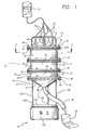
- FIG. 1 is a side sectional view of apparatus adapted for the isolation and collection of cells from donor tissue.
- FIG. 2 is a plan view taken along section lines 2-2 of FIG. 1.
- FIG. 1 depicts a system 10 adapted for use in the isolation and collection of living cells for later use in medical procedures.
- the system includes a cylindrical enclosure 12 constructed of a plurality of stacked annular segments 15, 18, and 20. These segments are fastened together to form the drum-like cylindrical enclosure.
- Each annular segment includes an upper and a lower flange.
- Annular segment 15 includes an upper flange 23 and a lower flange 25
- segment 18 includes an upper flange 27 and a lower flange 30
- segment 20 includes an upper flange 32 and a lower flange 38.
- the upper and lower flanges of adjacent segments are secured to one another by means of fasteners.
- these fasteners are bolts 40 and wing nuts 43. This arrangement allows for convenient assembly and disassembly of the system when access to the interior of the enclosure 12 is required during use or for cleaning.
- the cylindrical enclosure 12 is closed at its top and bottom ends, respectively, by an end plate 45 and a collection funnel 47.
- the end plate 45 is fastened to the upper flange 23 of annular segment 15 by bolts 40 and wing nuts 43.
- the collection funnel 47 includes a funnel flange 50, which is secured to the lower flange 38 of annular segment 20.
- Flexible O-rings 52, 55, 58, and 60 act as gaskets providing secure and reliable fluid-tight seals between adjacent parts of the enclosure.
- the end plate 45 has a handle 63 affixed to it so that the end plate can be conveniently removed from and installed against the upper flange 23 of the uppermost annular segment 15.
- end plate 45 depicted in FIG. 1 is in the form of a flat circular plate, other configurations may prove equally useful.
- the "end plate” could be in the form of a conical or hemispherical enclosure. Any part configured to seal an end of the enclosure 12 may be considered an "end plate” as that term is used herein.
- the end plate 45 further includes a plurality of inlet ports 65. Segments of inlet tubing 67 are connected to each of the inlet ports. Flexible coil springs 70 hold the inlet tubing straight in the region of the inlet ports so that an appropriate fluid can be conducted without restriction into the enclosure 12 from a supply bag 72 connected to the inlet tubing. At the bottom of the enclosure, an outlet port 75 at the tip of the collection funnel 47 allows fluid to drain out of the enclosure through a collection hose 78 and into a collection bag 80. The flow of fluid from the supply bag, through the enclosure, and into the collection bag will be described in more detail below.
- the constituent parts described above form a cylindrical enclosure 12 having an internal volume of approximately five liters. This internal volume is divided by mesh screening materials 83, 85, and 87 into three cylindrical chambers 90, 92, and 95, and a generally conical drain region 98 enclosed by the collection funnel 47.
- the individual screening materials are sandwiched between and held in place by the flanges 25, 27, 30, 32, 38, and 50 of the annular segments 15, 18, and 20, and the collection funnel 47.
- the preferred embodiment described herein includes three screening materials dividing adjacent chambers, it should be appreciated that more or fewer screening materials could be used, and the number of chambers varied thereby without departing in any way from the principles of the present invention.
- FIG. 2 is a plan view taken along section lines 2-2 of FIG. 1.
- FIG. 2 shows a section of the uppermost annular segment 15, that segment's lower flange 25, and the bolts 40 and wing nuts 43 that secure the lower flange of segment 15 to the upper flange (27, see FIG. 1) of segment 18.
- FIG. 2 also shows the uppermost mesh screening material 83.
- the screening material is a mesh material including a large number of openings or pores.
- the pores depicted in FIG. 2 are not to scale. The actual pores are much smaller than FIG. 2 would indicate.
- the screening material used in the actual apparatus is described in more detail below.
- the materials chosen for the system 10 should provide the desired qualities of durability, ease of assembly, and convenience of cleaning and sterilization.
- the annular segments 15, 18, and 20, the end plate 45, and the collection funnel 47 may all be formed of stainless steel or a similar suitable material.
- the material chosen for these parts is preferably durable enough to withstand repeated assembly, use, and disassembly, and should also be one that can be conveniently cleaned and sterilized.
- the interior surfaces of the enclosure 12 is advantageously smooth so that cells and fluids flow smoothly through the enclosure.
- the material chosen is preferably easy to machine or otherwise shape so that the various parts can be formed conveniently and economically.
- the O-rings 52, 55, 58, and 60 should be formed of a synthetic rubber or a similar flexible, durable material that provides a secure and reliable fluid-tight seal.
- the screening materials 83, 85, and 87 can be made of porous nylon sheets of appropriate size. Significantly, each of the individual screening materials has pores of preselected size. Generally, the pore size of the screening material will decrease from the upper to the lower part of the apparatus. The pore sizes of the different screening materials will generally fall within the range from ten to one thousand micrometers. In a particular embodiment of the invention, first screening material 83 includes pores approximately 400 micrometers in diameter, second screening material 85 has pores of about 280 micrometers, with third screening material 87 having pores of about 100 micrometers.
- the screening materials described herein are available from Tetko Inc. of Lancaster, New York.
- Screening materials having pores of the specified sizes have been found useful in the present invention.
- Typical hepatocytes are about 20 micrometers in diameter.
- the intent of the inventors in choosing the specified screening materials is to isolate mainly single hepatocytes with some doublets or triplets but few clusters comprised of more than three cells.
- the pore sizes of the selected screening materials could be varied somewhat without unduly impairing the performance of the invention.
- the inlet tubing 67 and collection hose 78 can be made of an appropriate medical grade plastic or synthetic rubber as is conventional in medical applications.
- the supply bag 72 and collection bag 80 will typically be of the type commonly used in medical applications to hold blood, saline, or other fluids.
- the assembled enclosure 12 is mounted on a pedestal 100 having legs 102 affixed to a base 105.
- the base of this pedestal is in turn positioned on a mechanical shaker 108.
- the shaker can be, for example, a Red RotorTM orbital shaker, available from Hoefer Scientific Instrument, Inc. of San Francisco, California.
- the end plate 45 is lifted off the top of the enclosure 12 to allow access to the interior of the enclosure.
- Chemically digested liver material from a suitable donor is placed inside the enclosure on top of the uppermost screening material 83. This liver material is in part a mass of cells including the hepatocytes that are to be collected, and in part extraneous materials from which those cells are to be isolated.
- the mechanical shaker is operated to gently oscillate the enclosure at 60 oscillations per minute. While the enclosure 12 is being shaken gently by the shaker 108, fluid from the supply bag 72 is conducted through the inlet tubing 67 into the upper portion of the enclosure and over the digested liver material. Ice-cold Dulbecco's Modified Eagle's Medium (DMEM; Sigma Chemicals, Saint Louis, Missouri) fortified with 10% bovine calf serum (BCS; Hyclone Laboratories, Inc., Logan, Utah) has been found to be a suitable fluid for use with digested porcine liver material.
- DMEM Dulbecco's Modified Eagle's Medium
- BCS Hyclone Laboratories, Inc., Logan, Utah
- the inlet ports 65 are configured to conduct fluid over the digested liver material and through the screening materials 83, 85, and 87.
- the fluid percolates over and through the liver material.
- Viable hepatocytes are entrained within the fluid and screened through each of the screening materials in sequence. From the screening materials, the fluid and entrained cells flow through the outlet port 75 out of the enclosure 12 and into the collection bag 80.
- the supply bag 72 and collection bag 80 seal the enclosure 12 and prevent communication of materials or pathogens from the outside environment. This sealed enclosure ensures sterility of the interior and contents of the system 10. Sterility of the collected cells is thereby made more secure than in conventional methods in which the cells are collected in open containers exposed to the environment.
- the collection bag holding the screened cell/fluid suspension is removed from the enclosure 12 and subjected to automated centrifugation and washing in a COBE 2991 blood cell processor, available from Blood Component Technology of Lakewood, Colorado.
- the digested liver material is placed in the uppermost chamber 90 inside the enclosure 12.
- the fluid is then conducted over the cellular material and through the screening materials 83, 85, and 87, thereby drawing the cells into the collection bag 80.
- the cells could be carried into the enclosure by the fluid in the form of a slurry or suspension. It will be appreciated that this alternative is effectively an equivalent in all significant respects to the preferred method described above.
- the inventors have found that the method described above tends to substantially reduce the time and labor required to isolate and collect liver cells from donor tissue. Additionally, cells collected using this method tend to have increased purity, viability, functionality, and structural integrity in comparison with cells obtained using conventional methods. Moreover, it is believed that the method of the invention will help to ensure the sterility of the collected cells in comparison with known methods.
Landscapes
- Health & Medical Sciences (AREA)
- Life Sciences & Earth Sciences (AREA)
- Engineering & Computer Science (AREA)
- Molecular Biology (AREA)
- Biomedical Technology (AREA)
- General Health & Medical Sciences (AREA)
- Surgery (AREA)
- Organic Chemistry (AREA)
- Chemical & Material Sciences (AREA)
- Animal Behavior & Ethology (AREA)
- Heart & Thoracic Surgery (AREA)
- Public Health (AREA)
- Veterinary Medicine (AREA)
- Pathology (AREA)
- Biotechnology (AREA)
- Bioinformatics & Cheminformatics (AREA)
- Medical Informatics (AREA)
- Zoology (AREA)
- Wood Science & Technology (AREA)
- Nuclear Medicine, Radiotherapy & Molecular Imaging (AREA)
- Oral & Maxillofacial Surgery (AREA)
- Biochemistry (AREA)
- General Engineering & Computer Science (AREA)
- Genetics & Genomics (AREA)
- Cell Biology (AREA)
- Microbiology (AREA)
- Sustainable Development (AREA)
- Apparatus Associated With Microorganisms And Enzymes (AREA)
- Investigating Or Analysing Biological Materials (AREA)
- Micro-Organisms Or Cultivation Processes Thereof (AREA)
- Immobilizing And Processing Of Enzymes And Microorganisms (AREA)
- Sampling And Sample Adjustment (AREA)
- External Artificial Organs (AREA)
- Measurement Of The Respiration, Hearing Ability, Form, And Blood Characteristics Of Living Organisms (AREA)
Abstract
Description
Currently, digested liver tissue is most often processed by washing and filtering the digested tissue manually through one or more screens or meshes having openings or pores of appropriate size.
Claims (17)
- An apparatus for collecting cells, the apparatus comprising:wherein the pores of the screening materials (83, 85, 87) having a diameter of between approximately ten and one thousand micrometers and are configured so that the fluid conducted out of the enclosure (12) contains substantially more single cells than doublets or triplets.a sealed enclosure (12);a plurality of screening materials (83, 85, 87) situated inside the enclosure (12), each screening material (83, 85, 87) defining pores of a predetermined size with pores in a first material being of a different size than pores in a second material;an inlet port (65) configured to conduct a fluid through the first and second screening materials;an outlet port (75) configured to receive the fluid from the first and second screening materials (83, 85, 87) and to conduct the fluid out of the enclosure (12);
- The apparatus of claim 1, wherein the sealed enclosure (12) includes a plurality of segments (15, 18, 20) joined to one another.
- The apparatus of claim 2, wherein each of the screening materials (83, 85, 87) is disposed between adjacent segments (15, 18, 20) of the sealed enclosure (12).
- The apparatus of claim 2, wherein the segments (15, 18, 20) include flanges (23, 25, 27, 30, 32, 38) adapted for use with fasteners (40, 43) to hold the segments (15, 18, 20) to one another.
- The apparatus according to any one of claims 1 to 4, further comprising:a plurality of segments (15, 18, 20) disposed against one another;an inlet port (65) configured to conduct fluid and in fluid communication with the interior of the sealed enclosure (12);an outlet port (75) configured to conduct fluid and in fluid communication with the interior of the sealed enclosure (12); anda plurality of screening materials (83, 85, 87) disposed inside the sealed enclosure (12) between the inlet port (65) and the outlet port (75).
- The apparatus according to any one of claims 1 to 5, further comprising: an end plate (45) joined to an end of one of the segments (15, 18, 20).
- The apparatus according to any one of claims 2 to 6, further comprising: a collection funnel (47) joined to an end of one of the segments (15, 18, 20).
- The apparatus according to any one of claims 2 to 7, wherein the screening materials (83, 85, 87) are disposed between adjacent segments (15, 18, 20) of the sealed enclosure (12).
- The apparatus according to any one of claims 1 to 8, wherein the pores of the said screening materials (83, 85, 87) being configured to filter out matter exceeding about 400, 280, and 100 micrometers, respectively, so that the fluid transmitted from the enclosure (12) contains more single cells than doublets or triplets and a quantity of cells not exceeding about 100 micrometers exits through the outlet port (75).
- A method for collecting cells, the method comprising:conducting a fluid into a sealed enclosure (12);entraining the cells within the fluid;flowing the fluid and entrained cells through at least first and second screening materials (83, 85, 87), each screening material defining pores of a predetermined size with pores of the first screening material being of a different size than the pores of the second screening material, such that cells that have passed through the materials contain substantially more single cells than doublets or triplets;conducting the fluid and the entrained cells out of the sealed enclosure (12) into a collection container (80); andcollecting the cells from the collection container (80).
- The method of claim 10, wherein entraining the cells within the fluid includes flowing the fluid over a cellular mass inside the sealed enclosure (12).
- The method of claim 10, wherein entraining the cells within the fluid is performed before the fluid is conducted into the sealed enclosure (12).
- The method of claim 10, further comprising: agitating the first and second screening materials (83, 85, 87) as the fluid and entrained cells are flowed through it.
- The method of claim 13, wherein agitating the first and second screening materials (83, 85, 87) includes operating a mechanical shaker (108) upon which the sealed enclosure (12) is supported.
- The method of claim 10, wherein the first screening material defines pores having a different predetermined size as compared with predetermined sized pores defined in the second screening material.
- The method of claim 10, comprising flowing the fluid and entrained cells sequentially through at least three distinct screening materials (83, 85, 87).
- The method of claim 16, wherein flowing the fluid and entrained cells sequentially through at least three distinct screening materials (83, 85, 87) includes flowing the fluid and entrained cells through screening materials (83, 85, 87) having pores of approximately 400, 280, and 100 micrometers.
Applications Claiming Priority (3)
| Application Number | Priority Date | Filing Date | Title |
|---|---|---|---|
| US08/484,717 US5888409A (en) | 1995-06-07 | 1995-06-07 | Methods for cell isolation and collection |
| PCT/US1996/009051 WO1996039979A1 (en) | 1995-06-07 | 1996-06-06 | Apparatus and methods for cell isolation and collection |
| US484717 | 2000-01-18 |
Publications (2)
| Publication Number | Publication Date |
|---|---|
| EP0830099A1 EP0830099A1 (en) | 1998-03-25 |
| EP0830099B1 true EP0830099B1 (en) | 2000-04-26 |
Family
ID=23925310
Family Applications (1)
| Application Number | Title | Priority Date | Filing Date |
|---|---|---|---|
| EP96917219A Expired - Lifetime EP0830099B1 (en) | 1995-06-07 | 1996-06-06 | Apparatus and methods for cell isolation and collection |
Country Status (10)
| Country | Link |
|---|---|
| US (2) | US5888409A (en) |
| EP (1) | EP0830099B1 (en) |
| JP (1) | JP2001525686A (en) |
| AT (1) | ATE192031T1 (en) |
| DE (1) | DE69607959T2 (en) |
| DK (1) | DK0830099T3 (en) |
| ES (1) | ES2147648T3 (en) |
| GR (1) | GR3033347T3 (en) |
| PT (1) | PT830099E (en) |
| WO (1) | WO1996039979A1 (en) |
Families Citing this family (41)
| Publication number | Priority date | Publication date | Assignee | Title |
|---|---|---|---|---|
| US6316247B1 (en) * | 1999-06-15 | 2001-11-13 | University Of Pittsburgh | System and method for refining liposuctioned adipose tissue |
| US6566145B2 (en) | 2000-02-09 | 2003-05-20 | William E Brewer | Disposable pipette extraction |
| US6623959B2 (en) | 2001-06-13 | 2003-09-23 | Ethicon, Inc. | Devices and methods for cell harvesting |
| US8105580B2 (en) | 2001-12-07 | 2012-01-31 | Cytori Therapeutics, Inc. | Methods of using adipose derived stem cells to promote wound healing |
| US7595043B2 (en) * | 2001-12-07 | 2009-09-29 | Cytori Therapeutics, Inc. | Method for processing and using adipose-derived stem cells |
| US7585670B2 (en) | 2001-12-07 | 2009-09-08 | Cytori Therapeutics, Inc. | Automated methods for isolating and using clinically safe adipose derived regenerative cells |
| KR100811995B1 (en) | 2001-12-07 | 2008-03-10 | 사이토리 테라퓨틱스, 인크. | Systems and methods for treating patients with treated lipoasperate cells |
| US20050095228A1 (en) | 2001-12-07 | 2005-05-05 | Fraser John K. | Methods of using regenerative cells in the treatment of peripheral vascular disease and related disorders |
| US7771716B2 (en) | 2001-12-07 | 2010-08-10 | Cytori Therapeutics, Inc. | Methods of using regenerative cells in the treatment of musculoskeletal disorders |
| US9597395B2 (en) * | 2001-12-07 | 2017-03-21 | Cytori Therapeutics, Inc. | Methods of using adipose tissue-derived cells in the treatment of cardiovascular conditions |
| US7651684B2 (en) | 2001-12-07 | 2010-01-26 | Cytori Therapeutics, Inc. | Methods of using adipose tissue-derived cells in augmenting autologous fat transfer |
| US8404229B2 (en) * | 2001-12-07 | 2013-03-26 | Cytori Therapeutics, Inc. | Methods of using adipose derived stem cells to treat acute tubular necrosis |
| US20030215935A1 (en) * | 2002-05-14 | 2003-11-20 | Coon David James | Apparatus and method for isolating living cells from an encapsulated organ tissue sample |
| JP4520855B2 (en) * | 2002-09-17 | 2010-08-11 | 株式会社 ジャパン・ティッシュ・エンジニアリング | Cell disperser, cell dispersal cassette and tissue holding member |
| US20080140451A1 (en) * | 2005-01-10 | 2008-06-12 | Cytori Therapeutics, Inc. | Devices and Methods for Monitoring, Managing, and Servicing Medical Devices |
| WO2007139551A1 (en) * | 2006-05-30 | 2007-12-06 | Cytori Therapeutics, Inc. | Systems and methods for manipulation of regenerative cells from adipose tissue |
| WO2008013863A2 (en) * | 2006-07-26 | 2008-01-31 | Cytori Therapeutics, Inc. | Generation of adipose tissue and adipocytes |
| DE102007005369A1 (en) | 2007-02-02 | 2008-08-07 | Eppendorf Ag | Device and method for the mechanical separation of cells from a cell network |
| JP2009038998A (en) * | 2007-08-07 | 2009-02-26 | Olympus Corp | Cell-separating device |
| WO2010021993A1 (en) | 2008-08-19 | 2010-02-25 | Cytori Therapeutics, Inc. | Methods of using adipose tissue-derived cells in the treatment of the lymphatic system and malignant disease |
| US20100112696A1 (en) * | 2008-11-03 | 2010-05-06 | Baxter International Inc. | Apparatus And Methods For Processing Tissue To Release Cells |
| US8309343B2 (en) | 2008-12-01 | 2012-11-13 | Baxter International Inc. | Apparatus and method for processing biological material |
| WO2010127310A1 (en) | 2009-05-01 | 2010-11-04 | Cytori Therapeutics, Inc. | Systems, methods and compositions for optimizing tissue and cell enriched grafts |
| US9296984B2 (en) | 2010-07-09 | 2016-03-29 | The Gid Group, Inc. | Tissue processing apparatus and method for processing adipose tissue |
| US9206387B2 (en) | 2010-07-09 | 2015-12-08 | The Gid Group, Inc. | Method and apparatus for processing adipose tissue |
| WO2013106655A1 (en) | 2012-01-11 | 2013-07-18 | The Gid Group, Inc. | Method for processing adipose tissue and processing apparatus |
| EP2590695B1 (en) | 2010-07-09 | 2024-11-20 | GID BIO, Inc. | Apparatus and methods relating to collecting and processing human biological material containing adipose |
| KR20140070527A (en) * | 2011-08-29 | 2014-06-10 | 스템퓨틱스 리서치 프라이빗 리미티드 | A system for isolating stromal vascular fraction (svf) cells from the adipose tissue and a method thereof |
| MX353212B (en) * | 2011-12-07 | 2018-01-08 | Cytovera Inc | Method and device for sample processing. |
| US9624462B2 (en) | 2012-01-04 | 2017-04-18 | Japan Tissue Engineering Co, Ltd. | Cell separation container |
| BR112015004003B1 (en) | 2012-09-06 | 2020-05-19 | The Gid Group, Inc. | apparatus for processing human biological material containing fibrous tissue and method for processing adipose tissue |
| WO2015035221A1 (en) | 2013-09-05 | 2015-03-12 | The Gid Group, Inc. | Tissue processing apparatus and method for processing adipose tissue |
| WO2015167768A1 (en) | 2014-05-02 | 2015-11-05 | Lifecell Corporation | Injection sensor with feedback mechanism |
| BR112018008050A2 (en) | 2015-10-21 | 2018-10-23 | Lifecell Corp | pipe management systems and methods |
| RU2728181C2 (en) | 2015-10-21 | 2020-07-28 | Лайфселл Корпорейшн | Systems and methods for controlling articles of medical purpose |
| US10729827B2 (en) | 2015-12-22 | 2020-08-04 | Lifecell Corporation | Syringe filling device for fat transfer |
| USD782693S1 (en) | 2016-01-14 | 2017-03-28 | DPX Technologies, LLC | Dispersive insert for pipette tips |
| WO2018044791A1 (en) | 2016-08-30 | 2018-03-08 | Lifecell Corporation | Systems and methods for medical device control |
| USD851777S1 (en) | 2017-01-30 | 2019-06-18 | Lifecell Corporation | Canister-type device for tissue processing |
| US11732233B2 (en) | 2017-07-18 | 2023-08-22 | Gid Bio, Inc. | Adipose tissue digestion system and tissue processing method |
| US11879121B2 (en) | 2021-04-20 | 2024-01-23 | CisNovo | Tissue disaggregation system and methods |
Family Cites Families (19)
| Publication number | Priority date | Publication date | Assignee | Title |
|---|---|---|---|---|
| US2999560A (en) * | 1956-12-20 | 1961-09-12 | Phillips Petroleum Co | Separation for flare systems |
| US2895615A (en) * | 1957-08-16 | 1959-07-21 | Richard W Oathout | Filter |
| DE2915624A1 (en) * | 1978-04-28 | 1979-11-08 | Earl Jacob Braxton | DEVICE FOR THE RECOVERY OF TRACE BIOLOGICAL COMPOUNDS FROM URINE |
| US5328614A (en) * | 1979-05-21 | 1994-07-12 | Matsumura Kenneth N | Methods and apparati for removing protein-bound molecules from body fluids |
| US4395493A (en) * | 1981-05-14 | 1983-07-26 | Coulter Electronics, Inc. | Monolayer device using filter techniques |
| US4685472A (en) * | 1984-01-23 | 1987-08-11 | Rudolph Muto | Specimen collector |
| US5372945A (en) * | 1985-06-06 | 1994-12-13 | Alchas; Paul G. | Device and method for collecting and processing fat tissue and procuring microvessel endothelial cells to produce endothelial cell product |
| EP0352286B1 (en) * | 1987-04-03 | 1994-06-22 | Gradipore Limited | Improvements relating to separation of charged molecules |
| GB8720253D0 (en) * | 1987-08-27 | 1987-10-07 | Cogent Ltd | Assay systems |
| US5301685A (en) * | 1989-01-10 | 1994-04-12 | Guirguis Raouf A | Method and apparatus for obtaining a cytology monolayer |
| US4954251A (en) * | 1989-01-31 | 1990-09-04 | Miles Inc. | Concentric microaggregate blood filter |
| US5137031A (en) * | 1989-09-18 | 1992-08-11 | La Mina Ltd. | Urine testing apparatus with urinary sediment device |
| CA2050773A1 (en) * | 1990-09-25 | 1992-03-26 | John A. Andresen | Automated pap test method and device |
| US5085773A (en) * | 1990-11-06 | 1992-02-04 | Allied-Signal Inc. | Anti-static fuel filter |
| US5280377A (en) * | 1991-06-28 | 1994-01-18 | Eastman Kodak Company | Beam scanning galvanometer with spring supported mirror |
| US5185086A (en) * | 1991-07-16 | 1993-02-09 | Steven Kaali | Method and system for treatment of blood and/or other body fluids and/or synthetic fluids using combined filter elements and electric field forces |
| US5286377A (en) * | 1992-09-09 | 1994-02-15 | James Galvan | Evaporative cooler water treatment device |
| US5409833A (en) * | 1993-07-01 | 1995-04-25 | Baxter International Inc. | Microvessel cell isolation apparatus |
| US5368729A (en) * | 1993-07-23 | 1994-11-29 | Whatman, Inc. | Solid phase extraction device |
-
1995
- 1995-06-07 US US08/484,717 patent/US5888409A/en not_active Expired - Lifetime
-
1996
- 1996-06-06 WO PCT/US1996/009051 patent/WO1996039979A1/en not_active Ceased
- 1996-06-06 DK DK96917219T patent/DK0830099T3/en active
- 1996-06-06 ES ES96917219T patent/ES2147648T3/en not_active Expired - Lifetime
- 1996-06-06 DE DE69607959T patent/DE69607959T2/en not_active Expired - Fee Related
- 1996-06-06 AT AT96917219T patent/ATE192031T1/en not_active IP Right Cessation
- 1996-06-06 PT PT96917219T patent/PT830099E/en unknown
- 1996-06-06 JP JP50146397A patent/JP2001525686A/en active Pending
- 1996-06-06 EP EP96917219A patent/EP0830099B1/en not_active Expired - Lifetime
-
1999
- 1999-01-29 US US09/240,731 patent/US5968356A/en not_active Expired - Lifetime
-
2000
- 2000-04-27 GR GR20000401021T patent/GR3033347T3/en not_active IP Right Cessation
Also Published As
| Publication number | Publication date |
|---|---|
| JP2001525686A (en) | 2001-12-11 |
| DE69607959T2 (en) | 2000-10-05 |
| DK0830099T3 (en) | 2000-08-28 |
| ATE192031T1 (en) | 2000-05-15 |
| US5968356A (en) | 1999-10-19 |
| WO1996039979A1 (en) | 1996-12-19 |
| PT830099E (en) | 2000-10-31 |
| EP0830099A1 (en) | 1998-03-25 |
| GR3033347T3 (en) | 2000-09-29 |
| ES2147648T3 (en) | 2000-09-16 |
| DE69607959D1 (en) | 2000-05-31 |
| US5888409A (en) | 1999-03-30 |
Similar Documents
| Publication | Publication Date | Title |
|---|---|---|
| US5888409A (en) | Methods for cell isolation and collection | |
| JP3693676B2 (en) | Method and apparatus for implanting microvascular cells on a synthetic vascular graft | |
| EP0984060B1 (en) | Microvessel cell isolation method and apparatus | |
| US9192361B2 (en) | Fecal microbiome transplant material preparation method and apparatus | |
| US9176026B2 (en) | Device for the collection, refinement, and administration of gastrointestinal microflora | |
| JP6208787B2 (en) | Apparatus and method for preparing tissue for transplantation, in particular adipose tissue, from leaflet fat extracted by liposuction | |
| US6316247B1 (en) | System and method for refining liposuctioned adipose tissue | |
| US20140193852A9 (en) | Adipose tissue collection and pre-processing devices for use in liposuction procedure | |
| JP6164612B2 (en) | Cell separation container | |
| EP0652976A4 (en) | Device and method for processing fat tissue to produce endothelial cell product. | |
| TWI385031B (en) | Apparatus and process for washing cell, tissue, or biological material | |
| JP2014525260A (en) | System and method for isolating stromal vascular fraction (SVF) cells from adipose tissue | |
| CA2033927A1 (en) | Device for collecting and processing fat tissue to produce endothelial cell product | |
| US20030215935A1 (en) | Apparatus and method for isolating living cells from an encapsulated organ tissue sample | |
| CN217202702U (en) | Separating device | |
| CN118678975B (en) | Portable extracorporeal blood cell gene modifying system | |
| CN117987242B (en) | SVF cell separation device and SVF cell separation method | |
| CN113999756A (en) | Separation device and method | |
| JP2003235542A (en) | Filter device | |
| JP2004159584A (en) | Endocrine cell concentrator |
Legal Events
| Date | Code | Title | Description |
|---|---|---|---|
| PUAI | Public reference made under article 153(3) epc to a published international application that has entered the european phase |
Free format text: ORIGINAL CODE: 0009012 |
|
| 17P | Request for examination filed |
Effective date: 19971027 |
|
| AK | Designated contracting states |
Kind code of ref document: A1 Designated state(s): AT BE CH DE DK ES FI FR GB GR IE IT LI LU MC NL PT SE |
|
| GRAG | Despatch of communication of intention to grant |
Free format text: ORIGINAL CODE: EPIDOS AGRA |
|
| 17Q | First examination report despatched |
Effective date: 19990609 |
|
| GRAG | Despatch of communication of intention to grant |
Free format text: ORIGINAL CODE: EPIDOS AGRA |
|
| GRAG | Despatch of communication of intention to grant |
Free format text: ORIGINAL CODE: EPIDOS AGRA |
|
| GRAH | Despatch of communication of intention to grant a patent |
Free format text: ORIGINAL CODE: EPIDOS IGRA |
|
| GRAH | Despatch of communication of intention to grant a patent |
Free format text: ORIGINAL CODE: EPIDOS IGRA |
|
| GRAA | (expected) grant |
Free format text: ORIGINAL CODE: 0009210 |
|
| AK | Designated contracting states |
Kind code of ref document: B1 Designated state(s): AT BE CH DE DK ES FI FR GB GR IE IT LI LU MC NL PT SE |
|
| REF | Corresponds to: |
Ref document number: 192031 Country of ref document: AT Date of ref document: 20000515 Kind code of ref document: T |
|
| REG | Reference to a national code |
Ref country code: CH Ref legal event code: NV Representative=s name: ISLER & PEDRAZZINI AG Ref country code: CH Ref legal event code: EP |
|
| REF | Corresponds to: |
Ref document number: 69607959 Country of ref document: DE Date of ref document: 20000531 |
|
| REG | Reference to a national code |
Ref country code: IE Ref legal event code: FG4D |
|
| ET | Fr: translation filed | ||
| ITF | It: translation for a ep patent filed | ||
| REG | Reference to a national code |
Ref country code: DK Ref legal event code: T3 |
|
| REG | Reference to a national code |
Ref country code: ES Ref legal event code: FG2A Ref document number: 2147648 Country of ref document: ES Kind code of ref document: T3 |
|
| REG | Reference to a national code |
Ref country code: PT Ref legal event code: SC4A Free format text: AVAILABILITY OF NATIONAL TRANSLATION Effective date: 20000714 |
|
| PGFP | Annual fee paid to national office [announced via postgrant information from national office to epo] |
Ref country code: SE Payment date: 20001207 Year of fee payment: 5 |
|
| PLBE | No opposition filed within time limit |
Free format text: ORIGINAL CODE: 0009261 |
|
| STAA | Information on the status of an ep patent application or granted ep patent |
Free format text: STATUS: NO OPPOSITION FILED WITHIN TIME LIMIT |
|
| 26N | No opposition filed | ||
| PGFP | Annual fee paid to national office [announced via postgrant information from national office to epo] |
Ref country code: GB Payment date: 20010606 Year of fee payment: 6 |
|
| PG25 | Lapsed in a contracting state [announced via postgrant information from national office to epo] |
Ref country code: SE Free format text: LAPSE BECAUSE OF NON-PAYMENT OF DUE FEES Effective date: 20010607 |
|
| PGFP | Annual fee paid to national office [announced via postgrant information from national office to epo] |
Ref country code: PT Payment date: 20010608 Year of fee payment: 6 |
|
| PGFP | Annual fee paid to national office [announced via postgrant information from national office to epo] |
Ref country code: FR Payment date: 20010611 Year of fee payment: 6 Ref country code: DE Payment date: 20010611 Year of fee payment: 6 |
|
| PGFP | Annual fee paid to national office [announced via postgrant information from national office to epo] |
Ref country code: DK Payment date: 20010613 Year of fee payment: 6 Ref country code: AT Payment date: 20010613 Year of fee payment: 6 |
|
| PGFP | Annual fee paid to national office [announced via postgrant information from national office to epo] |
Ref country code: FI Payment date: 20010614 Year of fee payment: 6 |
|
| PGFP | Annual fee paid to national office [announced via postgrant information from national office to epo] |
Ref country code: CH Payment date: 20010615 Year of fee payment: 6 |
|
| PGFP | Annual fee paid to national office [announced via postgrant information from national office to epo] |
Ref country code: GR Payment date: 20010621 Year of fee payment: 6 |
|
| PGFP | Annual fee paid to national office [announced via postgrant information from national office to epo] |
Ref country code: IE Payment date: 20010622 Year of fee payment: 6 |
|
| PGFP | Annual fee paid to national office [announced via postgrant information from national office to epo] |
Ref country code: NL Payment date: 20010628 Year of fee payment: 6 Ref country code: ES Payment date: 20010628 Year of fee payment: 6 |
|
| PGFP | Annual fee paid to national office [announced via postgrant information from national office to epo] |
Ref country code: LU Payment date: 20010629 Year of fee payment: 6 |
|
| PGFP | Annual fee paid to national office [announced via postgrant information from national office to epo] |
Ref country code: MC Payment date: 20010702 Year of fee payment: 6 |
|
| PGFP | Annual fee paid to national office [announced via postgrant information from national office to epo] |
Ref country code: BE Payment date: 20010816 Year of fee payment: 6 |
|
| REG | Reference to a national code |
Ref country code: GB Ref legal event code: IF02 |
|
| EUG | Se: european patent has lapsed |
Ref document number: 96917219.6 |
|
| PG25 | Lapsed in a contracting state [announced via postgrant information from national office to epo] |
Ref country code: MC Free format text: LAPSE BECAUSE OF NON-PAYMENT OF DUE FEES Effective date: 20020606 Ref country code: LU Free format text: LAPSE BECAUSE OF NON-PAYMENT OF DUE FEES Effective date: 20020606 Ref country code: IE Free format text: LAPSE BECAUSE OF NON-PAYMENT OF DUE FEES Effective date: 20020606 Ref country code: GB Free format text: LAPSE BECAUSE OF NON-PAYMENT OF DUE FEES Effective date: 20020606 Ref country code: FI Free format text: LAPSE BECAUSE OF NON-PAYMENT OF DUE FEES Effective date: 20020606 Ref country code: AT Free format text: LAPSE BECAUSE OF NON-PAYMENT OF DUE FEES Effective date: 20020606 |
|
| PG25 | Lapsed in a contracting state [announced via postgrant information from national office to epo] |
Ref country code: ES Free format text: LAPSE BECAUSE OF NON-PAYMENT OF DUE FEES Effective date: 20020607 |
|
| PG25 | Lapsed in a contracting state [announced via postgrant information from national office to epo] |
Ref country code: LI Free format text: LAPSE BECAUSE OF NON-PAYMENT OF DUE FEES Effective date: 20020630 Ref country code: CH Free format text: LAPSE BECAUSE OF NON-PAYMENT OF DUE FEES Effective date: 20020630 Ref country code: BE Free format text: LAPSE BECAUSE OF NON-PAYMENT OF DUE FEES Effective date: 20020630 |
|
| PG25 | Lapsed in a contracting state [announced via postgrant information from national office to epo] |
Ref country code: DK Free format text: LAPSE BECAUSE OF NON-PAYMENT OF DUE FEES Effective date: 20020731 |
|
| BERE | Be: lapsed |
Owner name: *CEDARS-SINAI MEDICAL CENTER Effective date: 20020630 |
|
| PG25 | Lapsed in a contracting state [announced via postgrant information from national office to epo] |
Ref country code: PT Free format text: LAPSE BECAUSE OF NON-PAYMENT OF DUE FEES Effective date: 20021231 Ref country code: GR Free format text: LAPSE BECAUSE OF NON-PAYMENT OF DUE FEES Effective date: 20021231 |
|
| PG25 | Lapsed in a contracting state [announced via postgrant information from national office to epo] |
Ref country code: NL Free format text: LAPSE BECAUSE OF NON-PAYMENT OF DUE FEES Effective date: 20030101 Ref country code: DE Free format text: LAPSE BECAUSE OF NON-PAYMENT OF DUE FEES Effective date: 20030101 |
|
| GBPC | Gb: european patent ceased through non-payment of renewal fee |
Effective date: 20020606 |
|
| REG | Reference to a national code |
Ref country code: CH Ref legal event code: PL |
|
| REG | Reference to a national code |
Ref country code: DK Ref legal event code: EBP |
|
| PG25 | Lapsed in a contracting state [announced via postgrant information from national office to epo] |
Ref country code: FR Free format text: LAPSE BECAUSE OF NON-PAYMENT OF DUE FEES Effective date: 20030228 |
|
| NLV4 | Nl: lapsed or anulled due to non-payment of the annual fee |
Effective date: 20030101 |
|
| REG | Reference to a national code |
Ref country code: PT Ref legal event code: MM4A Free format text: LAPSE DUE TO NON-PAYMENT OF FEES Effective date: 20021231 |
|
| REG | Reference to a national code |
Ref country code: IE Ref legal event code: MM4A |
|
| REG | Reference to a national code |
Ref country code: FR Ref legal event code: ST |
|
| REG | Reference to a national code |
Ref country code: ES Ref legal event code: FD2A Effective date: 20030711 |
|
| PG25 | Lapsed in a contracting state [announced via postgrant information from national office to epo] |
Ref country code: IT Free format text: LAPSE BECAUSE OF NON-PAYMENT OF DUE FEES Effective date: 20050606 |