EP0829742B1 - Method of manufacturing an optical cable for data transmission in local area networks - Google Patents
Method of manufacturing an optical cable for data transmission in local area networks Download PDFInfo
- Publication number
- EP0829742B1 EP0829742B1 EP97113383A EP97113383A EP0829742B1 EP 0829742 B1 EP0829742 B1 EP 0829742B1 EP 97113383 A EP97113383 A EP 97113383A EP 97113383 A EP97113383 A EP 97113383A EP 0829742 B1 EP0829742 B1 EP 0829742B1
- Authority
- EP
- European Patent Office
- Prior art keywords
- cable
- sheath
- yarns
- optical
- fibers
- Prior art date
- Legal status (The legal status is an assumption and is not a legal conclusion. Google has not performed a legal analysis and makes no representation as to the accuracy of the status listed.)
- Expired - Lifetime
Links
- 230000003287 optical effect Effects 0.000 title claims description 50
- 238000004519 manufacturing process Methods 0.000 title claims description 14
- 230000005540 biological transmission Effects 0.000 title description 11
- 239000013307 optical fiber Substances 0.000 claims description 28
- 238000001816 cooling Methods 0.000 claims description 17
- 238000000034 method Methods 0.000 claims description 17
- 229920003023 plastic Polymers 0.000 claims description 11
- 239000004033 plastic Substances 0.000 claims description 11
- 229920001169 thermoplastic Polymers 0.000 claims description 8
- 239000004416 thermosoftening plastic Substances 0.000 claims description 8
- 239000000835 fiber Substances 0.000 description 39
- 238000012360 testing method Methods 0.000 description 15
- 230000008602 contraction Effects 0.000 description 12
- 238000001125 extrusion Methods 0.000 description 10
- 239000010410 layer Substances 0.000 description 9
- 239000000463 material Substances 0.000 description 9
- 239000012815 thermoplastic material Substances 0.000 description 8
- 239000004753 textile Substances 0.000 description 7
- 239000011248 coating agent Substances 0.000 description 5
- 238000000576 coating method Methods 0.000 description 5
- 229920000642 polymer Polymers 0.000 description 5
- 239000004800 polyvinyl chloride Substances 0.000 description 5
- 229920000915 polyvinyl chloride Polymers 0.000 description 5
- 239000004760 aramid Substances 0.000 description 4
- 229920003235 aromatic polyamide Polymers 0.000 description 4
- 150000001875 compounds Chemical class 0.000 description 4
- 230000000694 effects Effects 0.000 description 4
- 230000001788 irregular Effects 0.000 description 4
- 229910052799 carbon Inorganic materials 0.000 description 3
- 230000006866 deterioration Effects 0.000 description 3
- 238000011161 development Methods 0.000 description 3
- 230000003014 reinforcing effect Effects 0.000 description 3
- XLYOFNOQVPJJNP-UHFFFAOYSA-N water Substances O XLYOFNOQVPJJNP-UHFFFAOYSA-N 0.000 description 3
- RNFJDJUURJAICM-UHFFFAOYSA-N 2,2,4,4,6,6-hexaphenoxy-1,3,5-triaza-2$l^{5},4$l^{5},6$l^{5}-triphosphacyclohexa-1,3,5-triene Chemical compound N=1P(OC=2C=CC=CC=2)(OC=2C=CC=CC=2)=NP(OC=2C=CC=CC=2)(OC=2C=CC=CC=2)=NP=1(OC=1C=CC=CC=1)OC1=CC=CC=C1 RNFJDJUURJAICM-UHFFFAOYSA-N 0.000 description 2
- ZOXJGFHDIHLPTG-UHFFFAOYSA-N Boron Chemical compound [B] ZOXJGFHDIHLPTG-UHFFFAOYSA-N 0.000 description 2
- 230000002159 abnormal effect Effects 0.000 description 2
- 150000001252 acrylic acid derivatives Chemical class 0.000 description 2
- 230000001464 adherent effect Effects 0.000 description 2
- 230000004075 alteration Effects 0.000 description 2
- 229920006231 aramid fiber Polymers 0.000 description 2
- 229910052796 boron Inorganic materials 0.000 description 2
- 239000003795 chemical substances by application Substances 0.000 description 2
- 238000005253 cladding Methods 0.000 description 2
- 229920001971 elastomer Polymers 0.000 description 2
- 239000002657 fibrous material Substances 0.000 description 2
- 239000003063 flame retardant Substances 0.000 description 2
- 229920002313 fluoropolymer Polymers 0.000 description 2
- 239000011521 glass Substances 0.000 description 2
- 239000003365 glass fiber Substances 0.000 description 2
- 238000009434 installation Methods 0.000 description 2
- 239000002861 polymer material Substances 0.000 description 2
- 230000001681 protective effect Effects 0.000 description 2
- 239000000779 smoke Substances 0.000 description 2
- 238000005728 strengthening Methods 0.000 description 2
- NIXOWILDQLNWCW-UHFFFAOYSA-M Acrylate Chemical compound [O-]C(=O)C=C NIXOWILDQLNWCW-UHFFFAOYSA-M 0.000 description 1
- 229920000178 Acrylic resin Polymers 0.000 description 1
- 239000004925 Acrylic resin Substances 0.000 description 1
- OKTJSMMVPCPJKN-UHFFFAOYSA-N Carbon Chemical compound [C] OKTJSMMVPCPJKN-UHFFFAOYSA-N 0.000 description 1
- 229920000049 Carbon (fiber) Polymers 0.000 description 1
- 239000004698 Polyethylene Substances 0.000 description 1
- 239000004917 carbon fiber Substances 0.000 description 1
- 238000004891 communication Methods 0.000 description 1
- 238000005056 compaction Methods 0.000 description 1
- 230000001595 contractor effect Effects 0.000 description 1
- 239000000806 elastomer Substances 0.000 description 1
- 230000008030 elimination Effects 0.000 description 1
- 238000003379 elimination reaction Methods 0.000 description 1
- 238000005516 engineering process Methods 0.000 description 1
- 230000009970 fire resistant effect Effects 0.000 description 1
- 238000005259 measurement Methods 0.000 description 1
- 239000002985 plastic film Substances 0.000 description 1
- 229920006255 plastic film Polymers 0.000 description 1
- -1 polyethylene Polymers 0.000 description 1
- 229920000573 polyethylene Polymers 0.000 description 1
- 229920002635 polyurethane Polymers 0.000 description 1
- 239000004814 polyurethane Substances 0.000 description 1
- 238000012545 processing Methods 0.000 description 1
- 230000005855 radiation Effects 0.000 description 1
- 230000002787 reinforcement Effects 0.000 description 1
- 229920005989 resin Polymers 0.000 description 1
- 239000011347 resin Substances 0.000 description 1
- 239000005060 rubber Substances 0.000 description 1
- 239000002356 single layer Substances 0.000 description 1
- 229920005992 thermoplastic resin Polymers 0.000 description 1
- 238000009827 uniform distribution Methods 0.000 description 1
Images



Classifications
-
- G—PHYSICS
- G02—OPTICS
- G02B—OPTICAL ELEMENTS, SYSTEMS OR APPARATUS
- G02B6/00—Light guides; Structural details of arrangements comprising light guides and other optical elements, e.g. couplings
- G02B6/44—Mechanical structures for providing tensile strength and external protection for fibres, e.g. optical transmission cables
- G02B6/4479—Manufacturing methods of optical cables
-
- G—PHYSICS
- G02—OPTICS
- G02B—OPTICAL ELEMENTS, SYSTEMS OR APPARATUS
- G02B6/00—Light guides; Structural details of arrangements comprising light guides and other optical elements, e.g. couplings
- G02B6/44—Mechanical structures for providing tensile strength and external protection for fibres, e.g. optical transmission cables
- G02B6/4401—Optical cables
- G02B6/441—Optical cables built up from sub-bundles
-
- G—PHYSICS
- G02—OPTICS
- G02B—OPTICAL ELEMENTS, SYSTEMS OR APPARATUS
- G02B6/00—Light guides; Structural details of arrangements comprising light guides and other optical elements, e.g. couplings
- G02B6/44—Mechanical structures for providing tensile strength and external protection for fibres, e.g. optical transmission cables
- G02B6/4401—Optical cables
- G02B6/4429—Means specially adapted for strengthening or protecting the cables
- G02B6/443—Protective covering
- G02B6/4432—Protective covering with fibre reinforcements
Definitions
- This invention refers to an optical cable for telecommunication, in particular for data transmission on local area networks, for example for use in offices, civil buildings, hospitals and similar.
- Telecommunication cables are known in which an optical core comprises at least one optical fiber surrounded by a number of protective coverings forming a single assembly, enveloped in turn by suitable means of reinforcement and covering.
- US patent 4,893,893 describes an optical cable for telecommunications comprising an optical fiber enveloped by a protective covering. At least one strand of fibrous material is deposited along the fiber and constitutes a strength member. An outer plastic layer surrounds the fibrous strand. Preferably three bundles of fibrous material are arranged equidistantly around the fiber, in a substantially longitudinal arrangement.
- Patent application FR 2321133 shows a fiber-optic rural transmission line consisting of fiber-optic cable housed in a flexible tube.
- Patent EP 0 468 878 refers to a fiber-optic communication cable, intended in particular for local area networks; the cable comprises a series of optical fibers placed inside a covering and divided into modules, each enveloped by a thin sheath. The sheaths are in contact with the optical fibers to engage them without decoupling, and the covering is in contact with the module sheaths to form a compact whole.
- EP-553,990 relates to an utility optical fiber cable which comprises a plurality of bundles of optical fibers and a yarn-like strength member system which is wrapped with an oscillated or unidirectional lay about the optical fibers.
- a jacket surrounds the yarn-like strength member system and it is tubed onto the cable core and then drawn down to form a loose fitting tubular member so that a tight fit of a pressure extruded jacket is avoided.
- GB-2,096,343 relates to an optical fiber cable which comprises a first and a second optical fiber coated and coupled together by a waterproof material cleanly peelable from the fibers, an inner sheath of plastic material surrounding the coated fibers, elongate strengthening strands running longitudinally of the cable around said inner sheath and an outer sheath of plastic material surrounding said elongate strengthening strands.
- GB-2,296,575 relates to a fiber-optic cable comprising at least one optical fiber, a primary coating which surrounds the optical fiber(s) and a rigid secondary coating forming a microreinforcement which surrounds the primary coating.
- the secondary coating is formed of resin coated rovings and the primary coating is a decoupling agent based on a thermoplastic material.
- the cable may have an external polymer jacket.
- Said document further discloses an apparatus for making the cable which includes a system for post-treating the decoupling agent, a constant speed haul off system and a constant tension take up.
- a pulling device In laying the cable, e.g. in the case of installation of optical cables in pipe, a pulling device must be applied to the head of the cable, connected to the reinforcing elements. This operation is particularly delicate, since the tensile load must be suitably applied to the reinforcing elements to avoid creating serious stress on some optical fibers, with the risk of breaking them or boosting attenuation in service.
- the Applicant has sought to produce an optical cable in which the attenuation of the optical fibers in service would remain low, the stress on the optical fibers caused in service by thermal shrinkage of the sheath would be negligible and the stress due to traction on the end of the cable during cable laying operations in pipe or similar would not jeopardize the integrity of one or more fibers.
- a plurality of traction-resistant yarns parallel to the cable interposed between the outer sheath of the cable and the optical modules comprising a number of fibers bundled by a common plastic covering, constituted a means of decoupling between sheath and fiber modules, such that in the cable manufacturing step, after extrusion of the sheath and during cooling, the sheath could not transmit the contractions of the plastic to the fibers, causing the aforesaid problems of attenuation measurable with known technology, at the same time minimizing the external dimensions of the cable.
- Irregular inflections of the cable were observed, particularly as a result of the thermal shrinkage of the cable in service, such as to cause a state of mechanical stressing of the fibers and a consequent deterioration of the transmission characteristics of the cable. This phenomenon was attributed to the presence of non-uniform adhesion between yarns and extruded sheath in the longitudinal direction.
- the invention is claimed in claim 1 and enables the fabrication of an optical cable comprising at least one optical module, comprising at least two optical fibers surrounded by a jacket of polymer material, an extruded outer sheath enveloping said modules and a strength member, wherein that said strength member comprises a plurality of tensile-resistant yarns, which occupy all the space between the optical modules and the outer sheath, in which said yarns adhere uniformly to the external sheath, said optical modules being mechanically decoupled from said outer sheath and the attenuation of the optical fibers of said optical modules in the cable being less than three times the nominal value of the optical fiber after at least a thermal cycle of 24 hours between -20 and +70°C.
- the optical cable preferably has an outside diameter between 2 and 7 mm.
- Said yarns preferably have a elastic tensile module of at least 4000 kg/mm 2 .
- said yarns are composed of aramid (aromatic polyamide) fibers.
- Said outer sheath is preferably of polyvinyl chloride.
- the polymer material of the jacket of said optical modules is preferably a cross-linked acrylic resin or, as an alternative, a flame-retardant polymer compound or a thermoplastic resin.
- the said uniform adherence of said yarns to the outer sheath is such that in a section of cable 500 mm long the regular unit force necessary to strip the outer sheath from the rest of the cable, comprising the yarns and optical modules, is between 20 and 60 g/mm, when the stripping force is applied at a rate of 15 mm/min.
- the said uniform adherence of said yarns to the outer sheath is such that in a section of cable 500 mm long the regular unit force necessary to strip an optical module from the remainder of the cable, comprising the yarns and outer sheath, is no greater than four times the unit operating strip force of an optical module with respect to the remainder of the cable, comprising the yarns and outer sheath.
- the force necessary in service to strip an optical module from the remainder of the cable, comprising the yarns and outer sheath is between 50 and 150 g per optical module, when the strip force is applied at a rate of 15 mm/min.
- the procedure of manufacturing an optical cable for telecommunication comprising at least one optical module with at least two optical fibers enveloped by a plastic jacket and a plastic sheath around the modules, which comprises the steps of:
- the procedure is characterized by the fact that said step of making yarns and sheath adhere uniformly to each other comprises flexing said cable by at least 90° the flexures being, performed in at least two mutually distinct planes.
- said flexures are performed in two mutually orthogonal planes.
- At least two flexures of essentially 180° each are performed in opposite directions.
- Figures 1 to 3 illustrate three examples of optical cable for telecommunication according to the invention, intended in particular for connecting local area networks, as inside offices, civil buildings, hospitals, etc.
- a cable obtained by the method according to the invention comprises a module 1, formed of two optical fibers 2, enveloped by a plastic jacket 3; the module in turn in contained inside a plastic sheath 4.
- the cable in figure 2 differs from the preceding one in that inside the sheath 4 there is a single module 1' inside of which there are four optical fibers, while the cable in figure 3 differs from the preceding one in that it comprises four modules 1', each with four fibers, inserted in a single sheath 4 and surrounded by the layer of tensile-resistant yarns 5.
- the cable could comprise any number of modules and that the fibers inside the modules could be three or more.
- the cable comprises a number of modules, and a number of fibers in each module, such that its total potential is between 2 and 20 fibers.
- each optical fiber is formed of a glass portion, with a core of 65 ⁇ m and cladding of 125 ⁇ m, surrounded by two layers of acrylates, designated collectively as the primary covering; as an altemative, each fiber is formed of a core of 65 ⁇ m and cladding of 100 ⁇ m, surrounded by three layers of acrylates of primary covering, resulting advantageously more flexible than the preceding one.
- the overall diameter of the optical fibers inclusive of primary covering is around 245-250 ⁇ m.
- modules with fibers of the first type and modules with fibers of the second type or cables in which one module comprises at the same time fibers of the first and second types (or of other known types) according to the specific service requirements.
- the jacket of the modules 1 is of a thermoplastic material, preferably extruded onto the fibers, for example a polyvinyl chloride or a fluorinated polymer and generally a fire-resistant thermoplastic material with limited smoke development or, again, a cross-linked acrylate, for example, by means of ultraviolet radiation.
- a thermoplastic material preferably extruded onto the fibers, for example a polyvinyl chloride or a fluorinated polymer and generally a fire-resistant thermoplastic material with limited smoke development or, again, a cross-linked acrylate, for example, by means of ultraviolet radiation.
- the thickness of the jacket is on the order of tenths of a millimeter (0.1-0.3 mm), so as to facilitate its removal for accessing the fibers and making the connections with other parts of the system, e.g. with the terminals of a computer.
- the sheath 4 is preferably of a thermoplastic material and may be made, for example, with polyvinyl chloride, fluoridated polymers, polymer compounds in flame-retardant thermoplastic material with low smoke development (known in the industry as LSOHs), with suitable characteristics of flame resistance and strippability for connectorizing to other parts of the system.
- the tensile-resistant yarns in the layer 5 have preferably a tensile modulus of at least 4000 kg/mm 2 , so at to endow the cable with characteristics of tensile resistance and limited deformability suited to its intended use.
- the yarns may be of the textile type or of other materials with characteristics comparable to textile yarns for flexibility and tensile resistance, such as fibers of glass, carbon, boron and similar.
- Textile yarns are intended as a preassembled group of elementary filaments, of aramid (aromatic polyamide) fiber in the preferential embodiment.
- Each textile yarn is identified by a count expressed in dTex, corresponding to the weight in grams of a 10 km length of yarn, and a corresponding tensile rigidity, measured in Newtons.
- the number of yarns, their count and rigidity depends on the characteristics required of the cable.
- the number of yarns is typically between 6 and 12, the dTex count between 1580 and 2400 and the overall rigidity between 72,750 and 181,000 Newtons.
- thermoplastic sheath 4 is applied by extrusion onto the surface of the layer of tensile-resistant yarns 5.
- the final diameter "D" of the cable measured on the sheath 4 is less than 4 mm and in figure 3 less than 7 mm.
- the cable in figure 2 has a module with a maximum sectional dimension on the jacket 3 of 0.95 mm and a diameter measured on the sheath 4 of 2.5 mm.
- the cable in figure 3 has modules with the same sectional dimension as that cited for figure 2 and diameter on the sheath 4 of 5 mm.
- the embodiments obtained by the method according to the invention include cables with more modules, with a potential of 2 to 72 fibers, with sheath thickness of 0.4 to 1.5 mm and outside sheath diameter of 2 to 7 mm.
- the method for manufacturing an optical cable with a core as illustrated in figure 1-3 includes the steps of advancing the core formed of a plurality of modules 1 continuously from a starting station to a collection station, extruding the sheath of thermoplastic material 4 around modules 1, cooling the sheath and collecting the core in the form of a coil or on a reel.
- the procedure according to the invention comprises the following basic steps:
- Phase a) favorably prevents the transmission of the contractions of the extruded sheath during the cooling step to the optical fibers of the modules with the negative result of greatly attenuating their transmission characteristics in the finished cable and in service.
- the decoupling between sheath and modules is achieved thanks to the fact that the yarns are caused to advance with a predetermined pull between the two processing stations and the modules are caused to advance between the same two stations with a pull controlled by a special brake on the respective feed reels.
- the sheath 4 extruded in the form of a plasticized mass, rests on a dense arrangement of yarns, inside of which the various modules 1 run.
- the cage formed by the yarns isolates the modules from the longitudinal contracting action of the sheath during the cooling step, allowing the sheath to transmit only a very limited radial contraction on the modules, if any, with a negligible effect on the transmission quality of the fibers.
- Phase b) creates the uniform adherence between yarns 5 and sheath 4, by means of repeated flexures of the core following the sheath cooling step.
- eliminating the points of adherence or increased adhesion prevents contractions of the sheath, due either to the natural structural shrinkage of the material after extrusion (thermal shrinkage) or to ambient temperature variations, from causing curving of the filaments arranged between the points of adhesion when the cable is under operating conditions, with consequent pressure on the modules and negative alteration of the transmission characteristics of the fibers.
- uniform adherence means the absence of zones in which the adhesion between sheath and yarns is greater than in adjacent zones, strong enough to prevent contractions of the sheath, e.g. thermal in nature, from being distributed over the entire structure of the cable, in both the circumferential and longitudinal directions.
- Figures 4, 5 show an embodiment of the line for manufacturing the cable with an optical core as illustrated in figures 1 to 3.
- the line comprises a first section, extending from the starting station to the sheath extrusion area, an intermediate section where the extruded thermoplastic sheath is cooled, an additional operating section for obtaining uniform adherence between the sheath and the yarns and a final section comprising the means for pulling and collecting the cable.
- the first section of the line includes a group 6 consisting of a number of decoilers 6a, 6b of optical modules 1 (two in the example shown) and a group 7 of decoilers of the yarns 5, both followed by means 8 for driving and positioning the modules and yarns at the entrance to an extruder 9, equipped with a head 10 into which the thermplastic material of the sheath is fed.
- Each optical module 1 is subjected to controlled tension, created by a motor-driven decoiler, as is each yarn 5.
- the drive and positioning means 8 distribute the modules 1 in a central position, in proximity to the axis of the extrusion head and yarns 5 according to a circular ring ordered within the extrusion head.
- thermoplastic material of the sheath is extruded onto the circumference created by the diameter of the yarn ring.
- the intermediate section of the line consisting of a water cooling tank 11, followed by an equalizing device 12, comprising means for creating the uniform adherence between yarns and sheath.
- cooling tank 11 comprises two sections, with hot water and water at ambient temperature, respectively.
- the final section of the line comprises a drawing system 13, followed by a takeup reel 14 with controlled draw.
- thermoplastic material of the sheath is consolidated in the cooling tank, so that the cable reaches the takeup reel substantially at ambient temperature.
- the textile yarns subject to traction independent of the optical modules, perform the aforesaid decoupling action between sheath and optical modules, preventing the transmission of stress to them resulting from the longitudinal contraction of the sheath in the cooling step.
- a limited radial contraction of the sheath advantageously reduces the empty spaces between the yarns, creating conditions of uniform compaction, helpful for increase the strength of the cable.
- the equalizing device 12 creates a state of uniform adherence between the sheath and the yarns, destroying possible local adherences or increases in adhesion along the cable, due, for example, to contract between the yarns and the melted polymer immediately downstream from the extrusion head.
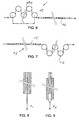
- the equalizing device 12 in a preferred embodiment, as shown in figures 6 and 7, comprises a plurality of drive pulleys arranged in sequence with contiguous pulleys at different heights, such that the cable on its undulated path passes over them partially hugging the external surface of the pulleys, alternatively first with its external surface and then with its internal surface.
- device 12 comprises at least a first plurality of pulleys arranged in one plane, followed by a second plurality of pulleys arranged in a plane angled with respect to the first.
- the device 12 comprises two series of pulleys 15, 16, arranged respectively on two mutually orthogonal planes, so as to obtain corresponding flexures of the cable in two orthogonal planes.
- the pulleys of the first series are preferably equal in number to those of the second series; also preferably, the diameters of the pulleys are all equal, within each series and between the two series.
- the number of pulleys of one series is between 3 and 9, and the value of the diameter 'd' of the pulleys 15,16 is between 20 and 40 times the diameter of the cable, causing a length 'L' of each series between 150 and 3000 mm.
- each of the two series comprises 7 pulleys, arranged in a section of length 'L' of around 550 mm, with diameter 'd' of each pulley around 90 mm.
- the distance between the two planes on which the centers of two contiguous pulleys are placed is between 1 and 2 times the diameter 'D' of each pulley.
- Two cables were prepared like those in figure 2, each comprising a single optical module with four optical fibers, surrounded by a layer of textile yarns 5 in aramid fiber and an external sheath of polyvinyl chloride having an internal diameter of 1.5 mm and an external diameter of 2.5 mm.
- optical fibers employed in the optical modules were single-mode fibers, marketed under the designation SMR by Fibre Ottiche Sud F.O.S. S.p.A., with a nominal attenuation of 0.2 dB/km.
- the optical module had a basically elliptical cross-section, with the larger dimension of around 0.95 mm and circumference of around 3 mm.
- a first cable was produced without the use of the equalizing device 12 and a second cable, of the same structure, was produced with the equalizing device 12.
- Specimens 500 mm long were cut from said cables and were subjected to testing to ascertain the force F required to strip module 1 from the rest of the cable specimen, consisting of the yarns 5 and the sheath 4.
- a first test was performed to measure the force F1 necessary to strip module 1 from the rest of the cable specimen (i.e. yarns and sheath).
- the testing conditions consisted of applying the load at a rate of 15 mm/minute and measuring the force necessary to strip the module and the sheath, respectively, first at startup and then under normal conditions, i.e. after overcoming the friction of first detachment.
- the stripping forces were measured in grams.
- said stripping load on the optical modules may vary between 50 and 150 g for each optical module and that the presence of the equalizing device results in changes of less than ⁇ 20% of said value.
- the value of the stripping force on the module measured in the test may be explained by the fact that the limited radial contraction of the sheath in the cooling process cause a certain compressive engagement of the sheath on the modules and said engagement results in a friction sufficient to generate the modest resistance to stripping indicated by the table data.
- results of the second test show the effect of the equalizing device in generating a uniform adherence between sheath and yarns to obtain the desired transmission characteristics of the cable fibers.
- the result may be explained by considering that the action of the equalizing device, thanks to the repeated flexures of the cable, eliminated or reduces the zones of greatest adhesion between sheath and yarns, distributed non-uniformly along the cable, which result in points of local increase in the force required to strip the sheath from the remaining cable structure.
- the cables were subjected to three successive thermal cycles for a duration of 4 hours per cycle.
- each cycle the temperature was caused to vary from +70°C to -30°C.
- each cycle comprised 2 hours of permanence at +70°C and 2 hours of permanence at -30°C.
- said thermal cycle will be indicated here below as a thermal cycle of 4 hours between +70°C and -30°C.
- the purpose of the test was to determine the effects of the structural shrinkage of the sheath under various conditions of adherence between sheath and yarns.
- the attenuation was measured in the cables employed in the cables described above.
- the cable subjected to equalization during its manufacture displayed an attenuation of ⁇ 0.5 dB/km at 1550 nm; after being subjected to three thermal cycles of 24 hours, each consisting of 12 hours of permanence at - 10°C and 12 hours of permanence at +60°C. it displayed an attenuation of ⁇ 0.5 dB/km at 1550 nm, i.e. essentially unchanged.
- this thermal cycle will be indicated below as "thermal cycle of 24 hours between -10 and +60°C”.
- the attenuation was measured, immediately after manufacture, at between 5 and 10 dB/km at 1550 nm; after the three thermal cycles of 24 hours between -10 and +60°C, as described above, the level of attenuation in the cable fibers reached such high values that it could not be measured with the available equipment (maximum dynamics of 15 dB at 1300 nm; the measurements were performed of cable specimens 500-1000 mm long).
- a cable was also produced with an optical module of four fibers, in which 62.5/125 multi-mode fibers produced by Corning were used; the fibers used has a nominal attenuation of ⁇ 1 dB/km at 1310 nm.
- the cable displayed an attenuation of ⁇ 1.5 dB/km at 1310 nm.
- the cables manufactured according to the invention displayed low values of attenuation of the optical signal; it is believed that these values are, in general, between the nominal value and about 3 times the nominal value of attenuation of the optical fiber employed.
- this includes cables with 1 to 7 optical modules, with 2 to 8 fibers per optical module, yarns of textile fiber (aramid fiber) or other materials with similar mechanical characteristics (flexibility, tensile resistance), such as glass fibers, carbon fibers, boron fibers or similar, sheath thickness between 0.4 and 1.5 mm, external sheath diameters between 2 and 7 mm; the sheath may be made, for example, of polyvinyl chloride, polyurethane, halogen-free elastomer compounds (known in the industry as LS0H compounds), fluorinated polymers, thermoplastic or cross-linked rubber and similar, according to the specific application requirements.
- textile fiber aramid fiber
- other materials with similar mechanical characteristics such as glass fibers, carbon fibers, boron fibers or similar
- sheath thickness between 0.4 and 1.5 mm
- external sheath diameters between 2 and 7 mm the sheath may be made, for example, of polyvinyl chloride, polyurethane, halogen-free elasto
Landscapes
- Physics & Mathematics (AREA)
- General Physics & Mathematics (AREA)
- Optics & Photonics (AREA)
- Engineering & Computer Science (AREA)
- Manufacturing & Machinery (AREA)
- Extrusion Moulding Of Plastics Or The Like (AREA)
- Optical Fibers, Optical Fiber Cores, And Optical Fiber Bundles (AREA)
- Communication Cables (AREA)
- Ropes Or Cables (AREA)
- Small-Scale Networks (AREA)
Description
- This invention refers to an optical cable for telecommunication, in particular for data transmission on local area networks, for example for use in offices, civil buildings, hospitals and similar.
- Telecommunication cables are known in which an optical core comprises at least one optical fiber surrounded by a number of protective coverings forming a single assembly, enveloped in turn by suitable means of reinforcement and covering.
- In particular, US patent 4,893,893 describes an optical cable for telecommunications comprising an optical fiber enveloped by a protective covering. At least one strand of fibrous material is deposited along the fiber and constitutes a strength member. An outer plastic layer surrounds the fibrous strand. Preferably three bundles of fibrous material are arranged equidistantly around the fiber, in a substantially longitudinal arrangement.
- Patent application FR 2321133 shows a fiber-optic rural transmission line consisting of fiber-optic cable housed in a flexible tube. In one example, a group of seven glass fibers 100 mm in diameter, each with a plastic covering 0.8 mm in outside diameter, is surrounded by a single layer consisting of a plastic film 300 µm thick, enveloped in turn by a polyethylene sheath 0.5 mm thick; said cable slides freely inside a flexible tube provided with reinforcing elements. Patent EP 0 468 878 refers to a fiber-optic communication cable, intended in particular for local area networks; the cable comprises a series of optical fibers placed inside a covering and divided into modules, each enveloped by a thin sheath. The sheaths are in contact with the optical fibers to engage them without decoupling, and the covering is in contact with the module sheaths to form a compact whole.
- EP-553,990 relates to an utility optical fiber cable which comprises a plurality of bundles of optical fibers and a yarn-like strength member system which is wrapped with an oscillated or unidirectional lay about the optical fibers. A jacket surrounds the yarn-like strength member system and it is tubed onto the cable core and then drawn down to form a loose fitting tubular member so that a tight fit of a pressure extruded jacket is avoided.
- GB-2,096,343 relates to an optical fiber cable which comprises a first and a second optical fiber coated and coupled together by a waterproof material cleanly peelable from the fibers, an inner sheath of plastic material surrounding the coated fibers, elongate strengthening strands running longitudinally of the cable around said inner sheath and an outer sheath of plastic material surrounding said elongate strengthening strands.
- GB-2,296,575 relates to a fiber-optic cable comprising at least one optical fiber, a primary coating which surrounds the optical fiber(s) and a rigid secondary coating forming a microreinforcement which surrounds the primary coating. The secondary coating is formed of resin coated rovings and the primary coating is a decoupling agent based on a thermoplastic material. The cable may have an external polymer jacket. Said document further discloses an apparatus for making the cable which includes a system for post-treating the decoupling agent, a constant speed haul off system and a constant tension take up.
- In laying the cable, e.g. in the case of installation of optical cables in pipe, a pulling device must be applied to the head of the cable, connected to the reinforcing elements. This operation is particularly delicate, since the tensile load must be suitably applied to the reinforcing elements to avoid creating serious stress on some optical fibers, with the risk of breaking them or boosting attenuation in service.
- The Applicant has sought to produce an optical cable in which the attenuation of the optical fibers in service would remain low, the stress on the optical fibers caused in service by thermal shrinkage of the sheath would be negligible and the stress due to traction on the end of the cable during cable laying operations in pipe or similar would not jeopardize the integrity of one or more fibers.
- In particular, the Applicant observed that operating according to the indications in patent EP 0 468 878, in which a thermoplastic sheath is extruded directly onto a plurality of optical modules, there were contractions of the sheath during cooling that could be transmitted to the optical fibers in each module, causing strong optical attenuation during cable service in some cases.
- The Applicant thus discovered that a plurality of traction-resistant yarns parallel to the cable interposed between the outer sheath of the cable and the optical modules, comprising a number of fibers bundled by a common plastic covering, constituted a means of decoupling between sheath and fiber modules, such that in the cable manufacturing step, after extrusion of the sheath and during cooling, the sheath could not transmit the contractions of the plastic to the fibers, causing the aforesaid problems of attenuation measurable with known technology, at the same time minimizing the external dimensions of the cable.
- Irregular inflections of the cable were observed, particularly as a result of the thermal shrinkage of the cable in service, such as to cause a state of mechanical stressing of the fibers and a consequent deterioration of the transmission characteristics of the cable. This phenomenon was attributed to the presence of non-uniform adhesion between yarns and extruded sheath in the longitudinal direction.
- It was then discovered that this deterioration could be eliminated by means of a particular mechanical treatment imparted to the cable during manufacturing, comprising repeated flexures of the cable such as to break the points of irregular adhesion, thus making yarns and sheath uniformly adherent and thus distributing stress uniformly inside the cable, thus without possible harmful snaking of the cable or irregular flexures occasioned by thermal shrinkage.
- It was also discovered that the placement of a single strength member between the outer sheath and the optical modules, in the form of yarns essentially parallel to the cable, could make it possible to effect, during installation in pipe, a single, simple connection between a specially-designed pulling chain and the aforesaid strength member, resulting in the uniform distribution of traction on the fibers.
- The invention is claimed in claim 1 and enables the fabrication of an optical cable comprising at least one optical module, comprising at least two optical fibers surrounded by a jacket of polymer material, an extruded outer sheath enveloping said modules and a strength member, wherein that said strength member comprises a plurality of tensile-resistant yarns, which occupy all the space between the optical modules and the outer sheath, in which said yarns adhere uniformly to the external sheath, said optical modules being mechanically decoupled from said outer sheath and the attenuation of the optical fibers of said optical modules in the cable being less than three times the nominal value of the optical fiber after at least a thermal cycle of 24 hours between -20 and +70°C.
- The optical cable preferably has an outside diameter between 2 and 7 mm. Said yarns preferably have a elastic tensile module of at least 4000 kg/mm2.
- In particular, said yarns are composed of aramid (aromatic polyamide) fibers.
- Said outer sheath is preferably of polyvinyl chloride.
- The polymer material of the jacket of said optical modules is preferably a cross-linked acrylic resin or, as an alternative, a flame-retardant polymer compound or a thermoplastic resin.
- The said uniform adherence of said yarns to the outer sheath is such that in a section of cable 500 mm long the regular unit force necessary to strip the outer sheath from the rest of the cable, comprising the yarns and optical modules, is between 20 and 60 g/mm, when the stripping force is applied at a rate of 15 mm/min. The said uniform adherence of said yarns to the outer sheath is such that in a section of cable 500 mm long the regular unit force necessary to strip an optical module from the remainder of the cable, comprising the yarns and outer sheath, is no greater than four times the unit operating strip force of an optical module with respect to the remainder of the cable, comprising the yarns and outer sheath.
- In a section of cable 500 mm long the force necessary in service to strip an optical module from the remainder of the cable, comprising the yarns and outer sheath, is between 50 and 150 g per optical module, when the strip force is applied at a rate of 15 mm/min.
- A coil of the cable in a configuration with at least two coils regularly in contact, with an outside diameter of around 160 mm, displays no significant polygonization when said coil is subject to at least a thermal cycle of 4 hours between +70 and -30°C.
- The procedure of manufacturing an optical cable for telecommunication, comprising at least one optical module with at least two optical fibers enveloped by a plastic jacket and a plastic sheath around the modules, which comprises the steps of:
- advancing said optical module continuously between a starting station and a collection station;
- extruding a thermoplastic sheath around the optical module;
- cooling said sheath,
- applying a layer of flexible, tensile-resistant yarns between module and sheath;
- extruding said thermoplastic sheath over said yarns;
- cooling said extruded sheath;
- making the yarns and sheath adhere uniformly to each other by removing points of adherence between sheath and yarns after the cooling of said extruded sheath.
- The procedure is characterized by the fact that said step of making yarns and sheath adhere uniformly to each other comprises flexing said cable by at least 90° the flexures being, performed in at least two mutually distinct planes.
- Preferably, said flexures are performed in two mutually orthogonal planes.
- In a preferred embodiment of the invention, at least two flexures of essentially 180° each are performed in opposite directions.
- Further details are provided by the following description, with reference to the figures enclosed, being exclusively intended as illustrative and not limitative, of which:
- figure 1 shows a cross-sectional view of a telecommunication cable obtained by the method according to the invention, in a first embodiment;
- figure 2 shows a cross-sectional view of a telecommunication cable obtained by the method according to the invention, in a second embodiment;
- figure 3 shows a cross-sectional view of a telecommunication cable obtained by the method according to the invention, in a third embodiment;
- figure 4 shoes a lateral view of a line for manufacturing the cable of figures 1-3;
- figure 5 shows a plan view of the line in figure 4;
- figure 6 shows a lateral view of an equalization device for the line in figure 4;
- figure 7 shows a plan view of an equalization device for the line in figure 4;
- figure 8 is a schematic representation of the testing method to determine the stripping load between the module and the rest of the cable;
- figure 9 is a schematic representation of the testing method to determine the stripping load between the sheath and the rest of the cable;
- figure 10 schematically shows a coil of cable manufactured with the device in figure 5, after exposure to the thermal cycles;
- figure 11 schematically shows a coil of cable manufactured without the device of figure 5, after exposure to the thermal cycles.
- Figures 1 to 3 illustrate three examples of optical cable for telecommunication according to the invention, intended in particular for connecting local area networks, as inside offices, civil buildings, hospitals, etc.
- As figure 1 shows, a cable obtained by the method according to the invention comprises a module 1, formed of two
optical fibers 2, enveloped by a plastic jacket 3; the module in turn in contained inside a plastic sheath 4. - Between the module 1 and the sheath 4 there is an interposed layer formed of a plurality of
longitudinal yarns 5, flexible and tensile-resistant, that fills the empty spaces between module and sheath. - The cable in figure 2 differs from the preceding one in that inside the sheath 4 there is a single module 1' inside of which there are four optical fibers, while the cable in figure 3 differs from the preceding one in that it comprises four modules 1', each with four fibers, inserted in a single sheath 4 and surrounded by the layer of tensile-
resistant yarns 5. - For simplicity of description, the identical elements in figures 1-3 have been indicated with the same numbering.
- It is also important to note that the cable could comprise any number of modules and that the fibers inside the modules could be three or more.
- Preferably, the cable comprises a number of modules, and a number of fibers in each module, such that its total potential is between 2 and 20 fibers.
- In one embodiment, each optical fiber is formed of a glass portion, with a core of 65 µm and cladding of 125 µm, surrounded by two layers of acrylates, designated collectively as the primary covering; as an altemative, each fiber is formed of a core of 65 µm and cladding of 100 µm, surrounded by three layers of acrylates of primary covering, resulting advantageously more flexible than the preceding one.
- In both the examples described, the overall diameter of the optical fibers inclusive of primary covering is around 245-250 µm.
- In particular embodiments there could be, in the same cable, modules with fibers of the first type and modules with fibers of the second type, or cables in which one module comprises at the same time fibers of the first and second types (or of other known types) according to the specific service requirements.
- The jacket of the modules 1 is of a thermoplastic material, preferably extruded onto the fibers, for example a polyvinyl chloride or a fluorinated polymer and generally a fire-resistant thermoplastic material with limited smoke development or, again, a cross-linked acrylate, for example, by means of ultraviolet radiation.
- The thickness of the jacket is on the order of tenths of a millimeter (0.1-0.3 mm), so as to facilitate its removal for accessing the fibers and making the connections with other parts of the system, e.g. with the terminals of a computer. The sheath 4 is preferably of a thermoplastic material and may be made, for example, with polyvinyl chloride, fluoridated polymers, polymer compounds in flame-retardant thermoplastic material with low smoke development (known in the industry as LSOHs), with suitable characteristics of flame resistance and strippability for connectorizing to other parts of the system.
- The tensile-resistant yarns in the
layer 5 have preferably a tensile modulus of at least 4000 kg/mm2, so at to endow the cable with characteristics of tensile resistance and limited deformability suited to its intended use. - The yarns may be of the textile type or of other materials with characteristics comparable to textile yarns for flexibility and tensile resistance, such as fibers of glass, carbon, boron and similar.
- Textile yarns are intended as a preassembled group of elementary filaments, of aramid (aromatic polyamide) fiber in the preferential embodiment.
- Each textile yarn is identified by a count expressed in dTex, corresponding to the weight in grams of a 10 km length of yarn, and a corresponding tensile rigidity, measured in Newtons.
- The number of yarns, their count and rigidity depends on the characteristics required of the cable.
- As an example, for the applications described earlier, in the embodiments of the present invention, the number of yarns is typically between 6 and 12, the dTex count between 1580 and 2400 and the overall rigidity between 72,750 and 181,000 Newtons.
- The thermoplastic sheath 4 is applied by extrusion onto the surface of the layer of tensile-
resistant yarns 5. - In the examples of figures 1 and 2, the final diameter "D" of the cable measured on the sheath 4 is less than 4 mm and in figure 3 less than 7 mm.
- In a particular embodiment, the cable in figure 2 has a module with a maximum sectional dimension on the jacket 3 of 0.95 mm and a diameter measured on the sheath 4 of 2.5 mm.
- In another embodiment, the cable in figure 3 has modules with the same sectional dimension as that cited for figure 2 and diameter on the sheath 4 of 5 mm.
- More generally, the embodiments obtained by the method according to the invention include cables with more modules, with a potential of 2 to 72 fibers, with sheath thickness of 0.4 to 1.5 mm and outside sheath diameter of 2 to 7 mm.
- The method for manufacturing an optical cable with a core as illustrated in figure 1-3 includes the steps of advancing the core formed of a plurality of modules 1 continuously from a starting station to a collection station, extruding the sheath of thermoplastic material 4 around modules 1, cooling the sheath and collecting the core in the form of a coil or on a reel.
- The procedure according to the invention comprises the following basic steps:
- a) decouple modules 1 and sheath 4 by interposing between them a plurality of flexible, tensile-
resistant yarns 5 subjected to pull from the starting station to the collection station; - b) make
yarns 5 and sheath 4 uniformly adherent at the output of the sheath cooling step. - Phase a) favorably prevents the transmission of the contractions of the extruded sheath during the cooling step to the optical fibers of the modules with the negative result of greatly attenuating their transmission characteristics in the finished cable and in service.
- The decoupling between sheath and modules is achieved thanks to the fact that the yarns are caused to advance with a predetermined pull between the two processing stations and the modules are caused to advance between the same two stations with a pull controlled by a special brake on the respective feed reels.
- The result is that the yarns and modules advance in the same direction independently at a constant rate imposed by a special motor at the end of the line.
- The sheath 4, extruded in the form of a plasticized mass, rests on a dense arrangement of yarns, inside of which the various modules 1 run.
- The cage formed by the yarns isolates the modules from the longitudinal contracting action of the sheath during the cooling step, allowing the sheath to transmit only a very limited radial contraction on the modules, if any, with a negligible effect on the transmission quality of the fibers.
- Phase b) creates the uniform adherence between
yarns 5 and sheath 4, by means of repeated flexures of the core following the sheath cooling step. - The mechanical action of repeated flexures is believed to destroy any links between the sheath and the yarns caused by points of adherence or increased adhesion, distributed non-uniformly between yarns and sheath in both the longitudinal and circumferential directions.
- Advantageously, eliminating the points of adherence or increased adhesion prevents contractions of the sheath, due either to the natural structural shrinkage of the material after extrusion (thermal shrinkage) or to ambient temperature variations, from causing curving of the filaments arranged between the points of adhesion when the cable is under operating conditions, with consequent pressure on the modules and negative alteration of the transmission characteristics of the fibers.
- For the purposes of the present invention, uniform adherence means the absence of zones in which the adhesion between sheath and yarns is greater than in adjacent zones, strong enough to prevent contractions of the sheath, e.g. thermal in nature, from being distributed over the entire structure of the cable, in both the circumferential and longitudinal directions.
- This result can be encouraged by either a virtual absence of adhesion between sheath and yarn or uniform adhesion of a controlled value.
- Figures 4, 5 show an embodiment of the line for manufacturing the cable with an optical core as illustrated in figures 1 to 3.
- The line comprises a first section, extending from the starting station to the sheath extrusion area, an intermediate section where the extruded thermoplastic sheath is cooled, an additional operating section for obtaining uniform adherence between the sheath and the yarns and a final section comprising the means for pulling and collecting the cable.
- In greater detail, the first section of the line includes a group 6 consisting of a number of decoilers 6a, 6b of optical modules 1 (two in the example shown) and a
group 7 of decoilers of theyarns 5, both followed bymeans 8 for driving and positioning the modules and yarns at the entrance to an extruder 9, equipped with ahead 10 into which the thermplastic material of the sheath is fed. - Each optical module 1 is subjected to controlled tension, created by a motor-driven decoiler, as is each
yarn 5. - The drive and positioning means 8 distribute the modules 1 in a central position, in proximity to the axis of the extrusion head and
yarns 5 according to a circular ring ordered within the extrusion head. - The thermoplastic material of the sheath is extruded onto the circumference created by the diameter of the yarn ring.
- Immediately downstream from the extrusion zone is the intermediate section of the line, consisting of a
water cooling tank 11, followed by an equalizingdevice 12, comprising means for creating the uniform adherence between yarns and sheath. - Preferably,
cooling tank 11 comprises two sections, with hot water and water at ambient temperature, respectively. - The final section of the line comprises a
drawing system 13, followed by atakeup reel 14 with controlled draw. - The thermoplastic material of the sheath is consolidated in the cooling tank, so that the cable reaches the takeup reel substantially at ambient temperature.
- In said cooling zone the textile yarns, subject to traction independent of the optical modules, perform the aforesaid decoupling action between sheath and optical modules, preventing the transmission of stress to them resulting from the longitudinal contraction of the sheath in the cooling step.
- In this same zone, a limited radial contraction of the sheath advantageously reduces the empty spaces between the yarns, creating conditions of uniform compaction, helpful for increase the strength of the cable.
- The equalizing
device 12, as said before, creates a state of uniform adherence between the sheath and the yarns, destroying possible local adherences or increases in adhesion along the cable, due, for example, to contract between the yarns and the melted polymer immediately downstream from the extrusion head. The equalizingdevice 12, in a preferred embodiment, as shown in figures 6 and 7, comprises a plurality of drive pulleys arranged in sequence with contiguous pulleys at different heights, such that the cable on its undulated path passes over them partially hugging the external surface of the pulleys, alternatively first with its external surface and then with its internal surface. - In particular,
device 12 comprises at least a first plurality of pulleys arranged in one plane, followed by a second plurality of pulleys arranged in a plane angled with respect to the first. - Preferably, as shown in figures 6 and 7, the
device 12 comprises two series ofpulleys - The pulleys of the first series are preferably equal in number to those of the second series; also preferably, the diameters of the pulleys are all equal, within each series and between the two series.
- As an example, the number of pulleys of one series is between 3 and 9, and the value of the diameter 'd' of the
pulleys - In one embodiment, relative to the cables in figures 1; 2 with diameter 'D' of around 2.5 mm, each of the two series comprises 7 pulleys, arranged in a section of length 'L' of around 550 mm, with diameter 'd' of each pulley around 90 mm.
- Preferably, the distance between the two planes on which the centers of two contiguous pulleys are placed is between 1 and 2 times the diameter 'D' of each pulley.
- Some tests were performed on cables of the type indicated, with the procedures indicated below.
- Two cables were prepared like those in figure 2, each comprising a single optical module with four optical fibers, surrounded by a layer of
textile yarns 5 in aramid fiber and an external sheath of polyvinyl chloride having an internal diameter of 1.5 mm and an external diameter of 2.5 mm. - The optical fibers employed in the optical modules were single-mode fibers, marketed under the designation SMR by Fibre Ottiche Sud F.O.S. S.p.A., with a nominal attenuation of 0.2 dB/km.
- The optical module had a basically elliptical cross-section, with the larger dimension of around 0.95 mm and circumference of around 3 mm.
- A first cable was produced without the use of the equalizing
device 12 and a second cable, of the same structure, was produced with the equalizingdevice 12. - Specimens 500 mm long were cut from said cables and were subjected to testing to ascertain the force F required to strip module 1 from the rest of the cable specimen, consisting of the
yarns 5 and the sheath 4. - A first test, diagrammed in figure 8, was performed to measure the force F1 necessary to strip module 1 from the rest of the cable specimen (i.e. yarns and sheath).
- A second test, diagrammed in figure 9, was performed on the same types of cable to measure the force F2 necessary to strip the sheath from the remaining portion of the cable, composed of module 1 and
yarns 5. - The testing conditions consisted of applying the load at a rate of 15 mm/minute and measuring the force necessary to strip the module and the sheath, respectively, first at startup and then under normal conditions, i.e. after overcoming the friction of first detachment. The stripping forces were measured in grams.
- The results of the test are indicated in the following Table 1, the
numbers 1 and 2 on the left indicating the tests with the cables produced with and without the equalizing device, respectively.
- The results of the first test, shown on the left side of the table, indicate that the stripping load on the module with respect to the rest of the cable structure is practically unchanged whether the cable was produced with the equalizing device or without it.
- In general, it is felt that said stripping load on the optical modules may vary between 50 and 150 g for each optical module and that the presence of the equalizing device results in changes of less than ±20% of said value.
- This result may be attributable to the fact that during the manufacture of the cable the optical modules remain in any case decoupled from the sheath.
- The value of the stripping force on the module measured in the test, small but still existent, may be explained by the fact that the limited radial contraction of the sheath in the cooling process cause a certain compressive engagement of the sheath on the modules and said engagement results in a friction sufficient to generate the modest resistance to stripping indicated by the table data.
- The results of the second test, shown on the right side of the table, show the effect of the equalizing device in generating a uniform adherence between sheath and yarns to obtain the desired transmission characteristics of the cable fibers.
- In fact, the stripping force of the sheath with respect to the underlying filaments was observed to assume values much higher when the cable was produced without the equalizing device than when the cable was produced with the use of the equalizing device.
- In particular, one may note from the table data that a stripping force without the use of the equalizing device was measured at around five times that measured for a cable produced with the equalizing device.
- In general, it is believed that for cables obtained by the method according to the present invention the force required to strip the sheath from the underlying filaments is reduced by 4 to 10 times when the equalizing device is used on the line and that the unit value of said force (referred to the circumferential development of the contact surface between sheath and yarns) varies between 20 and 60 g/mm.
- The result may be explained by considering that the action of the equalizing device, thanks to the repeated flexures of the cable, eliminated or reduces the zones of greatest adhesion between sheath and yarns, distributed non-uniformly along the cable, which result in points of local increase in the force required to strip the sheath from the remaining cable structure.
- The elimination of these zones of abnormal adhesion, due for example to particular conditions of contact of the sheath material with the yarns in the extrusion process, results in uniform adherence between sheath and yarns, due essentially to friction alone, such that, despite the presence of contraction of the sheath material during extrusion or thermal contractions during cable service, the stress is uniformly distributed toward the inside of the cable, thus avoiding the risk of abnormal local curving of the cable, with high pressure on the fibers of each module.
- Two sections 6 meters long of the test cables previously described, produced with and without the use of the equalizing device, respectively, were collected in coils with an average extemal diameter of 160 mm.
- Kept in the configuration indicated, the cables were subjected to three successive thermal cycles for a duration of 4 hours per cycle.
- In each cycle the temperature was caused to vary from +70°C to -30°C. In particular, each cycle comprised 2 hours of permanence at +70°C and 2 hours of permanence at -30°C. For the sake of brevity, said thermal cycle will be indicated here below as a thermal cycle of 4 hours between +70°C and -30°C.
- The purpose of the test was to determine the effects of the structural shrinkage of the sheath under various conditions of adherence between sheath and yarns.
- The final configurations assumed by the coils of the two cables are shown in figures 10 and 11, for the cable produced with and without the equalizing device, respectively.
- In the case of figure 10, after the thermal cycles there is a regular, concentric arrangement of the coils, with curvature essentially constant; the attenuation measured was less than 0.5 dB/km.
- In the case of figure 11, after the thermal cycles an accentuated polygonal configuration of the cable coils was observed.
- The attenuation was measured in the cables employed in the cables described above.
- In particular, the cable subjected to equalization during its manufacture displayed an attenuation of ≤ 0.5 dB/km at 1550 nm; after being subjected to three thermal cycles of 24 hours, each consisting of 12 hours of permanence at - 10°C and 12 hours of permanence at +60°C. it displayed an attenuation of ≤ 0.5 dB/km at 1550 nm, i.e. essentially unchanged. For the sake of brevity, this thermal cycle will be indicated below as "thermal cycle of 24 hours between -10 and +60°C".
- With the cable not subjected to equalization during manufacture the attenuation was measured, immediately after manufacture, at between 5 and 10 dB/km at 1550 nm; after the three thermal cycles of 24 hours between -10 and +60°C, as described above, the level of attenuation in the cable fibers reached such high values that it could not be measured with the available equipment (maximum dynamics of 15 dB at 1300 nm; the measurements were performed of cable specimens 500-1000 mm long).
- A cable was also produced with an optical module of four fibers, in which 62.5/125 multi-mode fibers produced by Corning were used; the fibers used has a nominal attenuation of ≤ 1 dB/km at 1310 nm.
- Both immediately after manufacture and after being subjected to three thermal cycles of 24 hours each between -10 and +60°C, as described above, the cable displayed an attenuation of ≤ 1.5 dB/km at 1310 nm.
- It is thus believed that the absence of the equalizing device leaves points of irregular adherence between sheath and yarns in the cable such that, following the thermal contractions of the sheath, the yarns are unable to slide between contiguous points of adherence with the sheath, causing a lack of uniformity in internal tensions and significant alterations of the geometrical arrangement such as to induce microbending stress in the fibers of the optical modules, responsible for the deterioration of transmission characteristics of the fibers observed during the testing.
- The cables manufactured according to the invention displayed low values of attenuation of the optical signal; it is believed that these values are, in general, between the nominal value and about 3 times the nominal value of attenuation of the optical fiber employed.
- Preferably, this includes cables with 1 to 7 optical modules, with 2 to 8 fibers per optical module, yarns of textile fiber (aramid fiber) or other materials with similar mechanical characteristics (flexibility, tensile resistance), such as glass fibers, carbon fibers, boron fibers or similar, sheath thickness between 0.4 and 1.5 mm, external sheath diameters between 2 and 7 mm; the sheath may be made, for example, of polyvinyl chloride, polyurethane, halogen-free elastomer compounds (known in the industry as LS0H compounds), fluorinated polymers, thermoplastic or cross-linked rubber and similar, according to the specific application requirements.
Claims (3)
- Method for the manufacture of an optical cable for telecommunication, said optical cable comprising:• at least one optical module (1) comprising at least two optical fibers (2) surrounded by a plastic jacket (3), and• an outer thermoplastic sheath (4) surrounding the optical module,said method comprising the steps of:- causing said optical module to continuously advance between a starting station and a collection station;- applying a layer (5) of flexible, tensile-resistant yarns in a position radially external to the optical module;- extruding the outer thermoplastic sheath over said layer of flexible, tensile-resistant yarns;- cooling said extruded outer sheath;- causing the yarns and the outer sheath to uniformly adhere to each other by flexing the cable by at least 90°,
characterized in that said step of flexing comprises the step of performing at least one flexure of the cable in at least two mutually distinct planes. - Method according to claim 1 characterized in that said mutually distinct planes are planes, which are perpendicular to each other.
- Method according to claim 1 characterized in that at least two flexures of roughly 180° each are executed in each plane, in opposite directions.
Applications Claiming Priority (2)
| Application Number | Priority Date | Filing Date | Title |
|---|---|---|---|
| ITMI961899 | 1996-09-16 | ||
| IT96MI001899A IT1284536B1 (en) | 1996-09-16 | 1996-09-16 | OPTICAL CABLE FOR DATA TRANSMISSION IN LOCAL NETWORKS |
Publications (3)
| Publication Number | Publication Date |
|---|---|
| EP0829742A1 EP0829742A1 (en) | 1998-03-18 |
| EP0829742B1 true EP0829742B1 (en) | 2006-01-25 |
| EP0829742B8 EP0829742B8 (en) | 2006-05-03 |
Family
ID=11374885
Family Applications (1)
| Application Number | Title | Priority Date | Filing Date |
|---|---|---|---|
| EP97113383A Expired - Lifetime EP0829742B8 (en) | 1996-09-16 | 1997-08-04 | Method of manufacturing an optical cable for data transmission in local area networks |
Country Status (10)
| Country | Link |
|---|---|
| US (1) | US5978536A (en) |
| EP (1) | EP0829742B8 (en) |
| AR (1) | AR009764A1 (en) |
| AU (1) | AU723727B2 (en) |
| BR (1) | BR9706844A (en) |
| CA (1) | CA2215639C (en) |
| DE (1) | DE69735151T2 (en) |
| ES (1) | ES2257758T3 (en) |
| IT (1) | IT1284536B1 (en) |
| NZ (1) | NZ328551A (en) |
Families Citing this family (38)
| Publication number | Priority date | Publication date | Assignee | Title |
|---|---|---|---|---|
| EP0939274A3 (en) * | 1998-02-25 | 2000-05-24 | Koninklijke Philips Electronics N.V. | Fibre optical cable with lateral diffusion of light |
| US6701047B1 (en) | 1999-03-31 | 2004-03-02 | Corning Cable Systems Llc | Fiber optic buffer unit and cables including the same |
| US6584251B1 (en) * | 2000-05-23 | 2003-06-24 | Alcatel | Solid stranding flextube unit |
| US6389204B1 (en) | 2001-05-30 | 2002-05-14 | Corning Cable Systems Llc | Fiber optic cables with strength members and methods of making the same |
| US6553167B2 (en) | 2001-06-04 | 2003-04-22 | Corning Cable Systems Llc | Fiber optic cables having ultra-low shrinking filaments and methods of making the same |
| US7210855B2 (en) | 2001-08-06 | 2007-05-01 | Pirelli & C. Spa | Device for connecting an optical fibre |
| US7123789B2 (en) | 2001-10-26 | 2006-10-17 | Pirelli & C. S.P.A. | Optical multi/demultiplexer device, optical wavelength selective filter and method of making filter |
| US6934452B2 (en) * | 2003-04-22 | 2005-08-23 | Furukawa Electric North America Inc. | Optical fiber cables |
| AU2003296755A1 (en) | 2003-12-24 | 2005-07-21 | Pirelli And C. S.P.A. | Connector for optical fibres |
| US7463812B2 (en) * | 2007-01-19 | 2008-12-09 | Adc Telecommunications, Inc. | Overhead cable termination arrangement |
| US8422843B2 (en) * | 2008-03-28 | 2013-04-16 | Adc Telecommunications, Inc. | Multi-fiber fiber optic cable |
| US8275225B2 (en) * | 2008-05-27 | 2012-09-25 | Adc Telecommunications, Inc. | Multi-jacketed fiber optic cable |
| WO2009155037A2 (en) | 2008-05-28 | 2009-12-23 | Adc Telecommunications, Inc. | Fiber optic cable |
| MX2011004384A (en) | 2008-10-28 | 2011-07-28 | Adc Telecommunications Inc | FLAT DOWN CABLE. |
| US8625944B1 (en) * | 2009-05-13 | 2014-01-07 | Draka Comteq, B.V. | Low-shrink reduced-diameter buffer tubes |
| US8625945B1 (en) * | 2009-05-13 | 2014-01-07 | Draka Comteq, B.V. | Low-shrink reduced-diameter dry buffer tubes |
| US8184935B2 (en) | 2009-10-21 | 2012-05-22 | Adc Telecommunications, Inc. | Flat drop cable with center strength member |
| WO2011063221A2 (en) | 2009-11-20 | 2011-05-26 | Adc Telecommunications, Inc. | Fiber optic cable |
| EP2517059B1 (en) * | 2009-12-23 | 2018-11-21 | Prysmian S.p.A. | Microbundle optical cable |
| GB2477946A (en) * | 2010-02-18 | 2011-08-24 | Paradigm B V | Transfer member assembly with settable material and shroud |
| EP2392957A1 (en) * | 2010-05-12 | 2011-12-07 | Nexans | Expanded four fiber unit cable design for increased fiber count cables having increased flexibility and fiber strength utilization |
| US8494327B2 (en) | 2010-10-19 | 2013-07-23 | Nexans | Expanded four fiber unit cable for increased fiber count cables having increased flexibility and fiber strength utilization |
| US8915659B2 (en) | 2010-05-14 | 2014-12-23 | Adc Telecommunications, Inc. | Splice enclosure arrangement for fiber optic cables |
| US8238706B2 (en) | 2010-05-19 | 2012-08-07 | Adc Telecommunications, Inc. | Flat drop cable with medial bump |
| US8885998B2 (en) | 2010-12-09 | 2014-11-11 | Adc Telecommunications, Inc. | Splice enclosure arrangement for fiber optic cables |
| US9739966B2 (en) | 2011-02-14 | 2017-08-22 | Commscope Technologies Llc | Fiber optic cable with electrical conductors |
| US8781281B2 (en) | 2011-07-21 | 2014-07-15 | Adc Telecommunications, Inc. | Drop cable with angled reinforcing member configurations |
| US9316802B2 (en) | 2012-08-24 | 2016-04-19 | Commscope Technologies Llc | Optical fiber cable having reinforcing layer of tape heat-bonded to jacket |
| US9594226B2 (en) | 2013-10-18 | 2017-03-14 | Corning Optical Communications LLC | Optical fiber cable with reinforcement |
| EP3068600B1 (en) * | 2013-11-15 | 2020-02-19 | SABIC Global Technologies B.V. | Process for producing a glass fibre-reinforced thermoplastic polymer composition |
| US10809475B2 (en) * | 2014-03-18 | 2020-10-20 | Corning Optical Communications LLC | Jacket for a fiber optic cable |
| US10222547B2 (en) | 2015-11-30 | 2019-03-05 | Corning Incorporated | Flame-retardant optical fiber coating |
| JP2018180361A (en) * | 2017-04-17 | 2018-11-15 | 住友電気工業株式会社 | Fiber optic cable |
| US10167396B2 (en) * | 2017-05-03 | 2019-01-01 | Corning Incorporated | Low smoke fire-resistant optical ribbon |
| US11364697B1 (en) | 2019-05-14 | 2022-06-21 | Apple Inc. | Methods of manufacturing fiber optic plates for electronic devices |
| EP3764144B1 (en) | 2019-07-09 | 2023-02-22 | Corning Research & Development Corporation | Flame retardant fiber optic cable with halogen free sheath for blowing applications |
| EP4102276A4 (en) * | 2020-02-06 | 2024-02-21 | Fujikura Ltd. | Optical fiber cable and manufacturing method for optical fiber cable |
| EP4027179B1 (en) * | 2021-01-12 | 2024-08-14 | Corning Research & Development Corporation | Flame retardant fiber optic cable with halogen free sheath for blowing applications |
Family Cites Families (13)
| Publication number | Priority date | Publication date | Assignee | Title |
|---|---|---|---|---|
| GB1483845A (en) * | 1975-08-14 | 1977-08-24 | Standard Telephones Cables Ltd | Land lines |
| US4269024A (en) * | 1978-08-01 | 1981-05-26 | Associated Electrical Industries Limited | Strength members for the reinforcement of optical fibre cables |
| GB2096343B (en) * | 1981-04-01 | 1984-08-15 | Pirelli General Plc | Optical fibre cable |
| EP0216548B1 (en) * | 1985-09-14 | 1995-03-08 | Nortel Networks Corporation | Optical fibre cable |
| US4893893A (en) * | 1986-01-31 | 1990-01-16 | American Telephone And Telegraph Co., At&T Bell Laboratories | Strengthened buffered optical fiber |
| IT1215529B (en) * | 1987-06-01 | 1990-02-14 | Pirelli Cavi Spa | OPTICAL FIBER CABLE. |
| US4787702A (en) * | 1987-10-26 | 1988-11-29 | Mark Products, Inc. | Fiber optic cable and method of making the same |
| GB2237655B (en) * | 1989-10-12 | 1993-04-28 | Stc Plc | Aerial optical fibre cable |
| FR2665266B1 (en) * | 1990-07-27 | 1993-07-30 | Silec Liaisons Elec | FIBER OPTIC TELECOMMUNICATION CABLE. |
| US5345525A (en) * | 1992-01-28 | 1994-09-06 | At&T Bell Laboratories | Utility optical fiber cable |
| FR2728694B1 (en) * | 1994-12-22 | 1997-03-14 | France Telecom | MODULE FOR FIBER OPTIC CABLES, MANUFACTURING METHOD AND INSTALLATION THEREFOR |
| US5627932A (en) * | 1995-08-23 | 1997-05-06 | Siecor Corporation | Reduced diameter indoor fiber optic cable |
| US5822485A (en) * | 1997-01-13 | 1998-10-13 | Siecor Corporation | Optical cable containing parallel flexible strength members and method |
-
1996
- 1996-09-16 IT IT96MI001899A patent/IT1284536B1/en active IP Right Grant
-
1997
- 1997-08-04 ES ES97113383T patent/ES2257758T3/en not_active Expired - Lifetime
- 1997-08-04 DE DE69735151T patent/DE69735151T2/en not_active Expired - Lifetime
- 1997-08-04 EP EP97113383A patent/EP0829742B8/en not_active Expired - Lifetime
- 1997-08-11 NZ NZ328551A patent/NZ328551A/en not_active IP Right Cessation
- 1997-08-29 AU AU36735/97A patent/AU723727B2/en not_active Ceased
- 1997-09-12 AR ARP970104182A patent/AR009764A1/en active IP Right Grant
- 1997-09-12 US US08/928,649 patent/US5978536A/en not_active Expired - Lifetime
- 1997-09-15 CA CA002215639A patent/CA2215639C/en not_active Expired - Fee Related
- 1997-09-16 BR BR9706844-6A patent/BR9706844A/en not_active IP Right Cessation
Also Published As
| Publication number | Publication date |
|---|---|
| BR9706844A (en) | 2000-11-28 |
| EP0829742B8 (en) | 2006-05-03 |
| CA2215639A1 (en) | 1998-03-16 |
| US5978536A (en) | 1999-11-02 |
| CA2215639C (en) | 2007-05-29 |
| DE69735151T2 (en) | 2006-10-26 |
| AU723727B2 (en) | 2000-09-07 |
| AU3673597A (en) | 1998-03-19 |
| AR009764A1 (en) | 2000-05-03 |
| NZ328551A (en) | 1997-12-19 |
| EP0829742A1 (en) | 1998-03-18 |
| ES2257758T3 (en) | 2006-08-01 |
| IT1284536B1 (en) | 1998-05-21 |
| ITMI961899A1 (en) | 1998-03-16 |
| DE69735151D1 (en) | 2006-04-13 |
Similar Documents
| Publication | Publication Date | Title |
|---|---|---|
| CA2215639C (en) | Optical cable for data transmission on local area networks | |
| US5201020A (en) | Reinforced protective tube for optical waveguide fibers | |
| US5822485A (en) | Optical cable containing parallel flexible strength members and method | |
| US5627932A (en) | Reduced diameter indoor fiber optic cable | |
| US8682123B2 (en) | Adhesively coupled optical fibers and enclosing tape | |
| US6785450B2 (en) | Self-supporting fiber optic cable | |
| EP1846790B1 (en) | Low shrink telecommunications cable and methods for manufacturing the same | |
| EP1895340B1 (en) | A loose tube optical waveguide fiber cable | |
| EP1895339B1 (en) | A loose tube optical waveguide cable | |
| JPH05142454A (en) | Composite buffer cable | |
| EP1646901A2 (en) | Fiber optic articles, assemblies, and cables having optical waveguides | |
| CN102016673A (en) | Multi-fiber fiber optic cable | |
| US20020181906A1 (en) | Fiber optic cables having ultra-low shrinking filaments and methods of making the same | |
| CA2541953C (en) | Fiber optic assemblies, cables, and manufacturing methods therefor | |
| GB2296575A (en) | Fibre optic cable ,manufacturing process and plant | |
| JP2002541509A (en) | Optical cable for telecommunications | |
| US6853780B1 (en) | Optical cable for telecommunications | |
| US6625365B2 (en) | Overcoated fiber for use in optical fiber cable | |
| EP0877269B1 (en) | Over-coated optical fiber and manufacturing method thereof | |
| EP3314322A1 (en) | An aerial micromodule optical cable and a method of manufacturing said cable | |
| HK1110123B (en) | Low shrink telecommunications cable and methods for manufacturing the same |
Legal Events
| Date | Code | Title | Description |
|---|---|---|---|
| PUAI | Public reference made under article 153(3) epc to a published international application that has entered the european phase |
Free format text: ORIGINAL CODE: 0009012 |
|
| AK | Designated contracting states |
Kind code of ref document: A1 Designated state(s): DE ES FR GB IT NL SE |
|
| 17P | Request for examination filed |
Effective date: 19980915 |
|
| AKX | Designation fees paid |
Free format text: DE ES FR GB IT NL SE |
|
| RBV | Designated contracting states (corrected) |
Designated state(s): DE ES FR GB IT NL SE |
|
| RBV | Designated contracting states (corrected) |
Designated state(s): DE ES FR GB IT NL SE |
|
| RAP1 | Party data changed (applicant data changed or rights of an application transferred) |
Owner name: PIRELLI S.P.A. |
|
| RAP1 | Party data changed (applicant data changed or rights of an application transferred) |
Owner name: PIRELLI & C. S.P.A. |
|
| 17Q | First examination report despatched |
Effective date: 20040524 |
|
| GRAP | Despatch of communication of intention to grant a patent |
Free format text: ORIGINAL CODE: EPIDOSNIGR1 |
|
| RTI1 | Title (correction) |
Free format text: METHOD OF MANUFACTURING AN OPTICAL CABLE FOR DATA TRANSMISSION IN LOCAL AREA NETWORKS |
|
| GRAS | Grant fee paid |
Free format text: ORIGINAL CODE: EPIDOSNIGR3 |
|
| GRAA | (expected) grant |
Free format text: ORIGINAL CODE: 0009210 |
|
| AK | Designated contracting states |
Kind code of ref document: B1 Designated state(s): DE ES FR GB IT NL SE |
|
| REG | Reference to a national code |
Ref country code: GB Ref legal event code: FG4D |
|
| RAP2 | Party data changed (patent owner data changed or rights of a patent transferred) |
Owner name: PRYSMIAN CAVI E SISTEMI ENERGIA S.R.L. |
|
| REF | Corresponds to: |
Ref document number: 69735151 Country of ref document: DE Date of ref document: 20060413 Kind code of ref document: P |
|
| REG | Reference to a national code |
Ref country code: SE Ref legal event code: TRGR |
|
| NLT2 | Nl: modifications (of names), taken from the european patent patent bulletin |
Owner name: PRYSMIAN CAVI E SISTEMI ENERGIA S.R.L. Effective date: 20060308 |
|
| REG | Reference to a national code |
Ref country code: ES Ref legal event code: FG2A Ref document number: 2257758 Country of ref document: ES Kind code of ref document: T3 |
|
| ET | Fr: translation filed | ||
| NLXE | Nl: other communications concerning ep-patents (part 3 heading xe) |
Free format text: PAT. BUL. 07/2006, PAGE 979: CORR.: PRYSMIAN CAVI E SISTEMI ENERGIA S.R.L. |
|
| PLBE | No opposition filed within time limit |
Free format text: ORIGINAL CODE: 0009261 |
|
| STAA | Information on the status of an ep patent application or granted ep patent |
Free format text: STATUS: NO OPPOSITION FILED WITHIN TIME LIMIT |
|
| 26N | No opposition filed |
Effective date: 20061026 |
|
| REG | Reference to a national code |
Ref country code: FR Ref legal event code: PLFP Year of fee payment: 19 |
|
| PGFP | Annual fee paid to national office [announced via postgrant information from national office to epo] |
Ref country code: NL Payment date: 20150826 Year of fee payment: 19 |
|
| PGFP | Annual fee paid to national office [announced via postgrant information from national office to epo] |
Ref country code: DE Payment date: 20150827 Year of fee payment: 19 Ref country code: GB Payment date: 20150827 Year of fee payment: 19 Ref country code: ES Payment date: 20150826 Year of fee payment: 19 |
|
| PGFP | Annual fee paid to national office [announced via postgrant information from national office to epo] |
Ref country code: FR Payment date: 20150817 Year of fee payment: 19 Ref country code: SE Payment date: 20150827 Year of fee payment: 19 |
|
| PGFP | Annual fee paid to national office [announced via postgrant information from national office to epo] |
Ref country code: IT Payment date: 20150825 Year of fee payment: 19 |
|
| REG | Reference to a national code |
Ref country code: DE Ref legal event code: R119 Ref document number: 69735151 Country of ref document: DE |
|
| REG | Reference to a national code |
Ref country code: SE Ref legal event code: EUG |
|
| REG | Reference to a national code |
Ref country code: NL Ref legal event code: MM Effective date: 20160901 |
|
| GBPC | Gb: european patent ceased through non-payment of renewal fee |
Effective date: 20160804 |
|
| PG25 | Lapsed in a contracting state [announced via postgrant information from national office to epo] |
Ref country code: SE Free format text: LAPSE BECAUSE OF NON-PAYMENT OF DUE FEES Effective date: 20160805 |
|
| REG | Reference to a national code |
Ref country code: FR Ref legal event code: ST Effective date: 20170428 |
|
| PG25 | Lapsed in a contracting state [announced via postgrant information from national office to epo] |
Ref country code: NL Free format text: LAPSE BECAUSE OF NON-PAYMENT OF DUE FEES Effective date: 20160901 |
|
| PG25 | Lapsed in a contracting state [announced via postgrant information from national office to epo] |
Ref country code: DE Free format text: LAPSE BECAUSE OF NON-PAYMENT OF DUE FEES Effective date: 20170301 Ref country code: FR Free format text: LAPSE BECAUSE OF NON-PAYMENT OF DUE FEES Effective date: 20160831 Ref country code: GB Free format text: LAPSE BECAUSE OF NON-PAYMENT OF DUE FEES Effective date: 20160804 |
|
| PG25 | Lapsed in a contracting state [announced via postgrant information from national office to epo] |
Ref country code: IT Free format text: LAPSE BECAUSE OF NON-PAYMENT OF DUE FEES Effective date: 20160804 |
|
| REG | Reference to a national code |
Ref country code: ES Ref legal event code: FD2A Effective date: 20180507 |
|
| PG25 | Lapsed in a contracting state [announced via postgrant information from national office to epo] |
Ref country code: ES Free format text: LAPSE BECAUSE OF NON-PAYMENT OF DUE FEES Effective date: 20160805 |