EP0829196B1 - Electric lawn mower - Google Patents
Electric lawn mower Download PDFInfo
- Publication number
- EP0829196B1 EP0829196B1 EP97116022A EP97116022A EP0829196B1 EP 0829196 B1 EP0829196 B1 EP 0829196B1 EP 97116022 A EP97116022 A EP 97116022A EP 97116022 A EP97116022 A EP 97116022A EP 0829196 B1 EP0829196 B1 EP 0829196B1
- Authority
- EP
- European Patent Office
- Prior art keywords
- housing
- cutter
- discharge port
- electric motor
- lawn mower
- Prior art date
- Legal status (The legal status is an assumption and is not a legal conclusion. Google has not performed a legal analysis and makes no representation as to the accuracy of the status listed.)
- Expired - Lifetime
Links
- 244000025254 Cannabis sativa Species 0.000 claims description 20
- 241001494496 Leersia Species 0.000 claims description 6
- 238000007599 discharging Methods 0.000 claims description 6
- 230000000630 rising effect Effects 0.000 claims description 2
- 230000005540 biological transmission Effects 0.000 description 12
- 239000000428 dust Substances 0.000 description 4
- 241001247986 Calotropis procera Species 0.000 description 3
- 238000010276 construction Methods 0.000 description 3
- 230000003796 beauty Effects 0.000 description 1
- 230000005484 gravity Effects 0.000 description 1
- 238000012423 maintenance Methods 0.000 description 1
- 239000002184 metal Substances 0.000 description 1
- XLYOFNOQVPJJNP-UHFFFAOYSA-N water Substances O XLYOFNOQVPJJNP-UHFFFAOYSA-N 0.000 description 1
Images




Classifications
-
- A—HUMAN NECESSITIES
- A01—AGRICULTURE; FORESTRY; ANIMAL HUSBANDRY; HUNTING; TRAPPING; FISHING
- A01D—HARVESTING; MOWING
- A01D69/00—Driving mechanisms or parts thereof for harvesters or mowers
- A01D69/02—Driving mechanisms or parts thereof for harvesters or mowers electric
-
- A—HUMAN NECESSITIES
- A01—AGRICULTURE; FORESTRY; ANIMAL HUSBANDRY; HUNTING; TRAPPING; FISHING
- A01D—HARVESTING; MOWING
- A01D34/00—Mowers; Mowing apparatus of harvesters
- A01D34/01—Mowers; Mowing apparatus of harvesters characterised by features relating to the type of cutting apparatus
- A01D34/412—Mowers; Mowing apparatus of harvesters characterised by features relating to the type of cutting apparatus having rotating cutters
- A01D34/63—Mowers; Mowing apparatus of harvesters characterised by features relating to the type of cutting apparatus having rotating cutters having cutters rotating about a vertical axis
- A01D34/76—Driving mechanisms for the cutters
- A01D34/78—Driving mechanisms for the cutters electric
-
- A—HUMAN NECESSITIES
- A01—AGRICULTURE; FORESTRY; ANIMAL HUSBANDRY; HUNTING; TRAPPING; FISHING
- A01D—HARVESTING; MOWING
- A01D34/00—Mowers; Mowing apparatus of harvesters
- A01D34/01—Mowers; Mowing apparatus of harvesters characterised by features relating to the type of cutting apparatus
- A01D34/412—Mowers; Mowing apparatus of harvesters characterised by features relating to the type of cutting apparatus having rotating cutters
- A01D34/63—Mowers; Mowing apparatus of harvesters characterised by features relating to the type of cutting apparatus having rotating cutters having cutters rotating about a vertical axis
- A01D34/81—Casings; Housings
Definitions
- the present invention relates to an electric lawn mower of a walking type in which a lawn is cut by rotating a cutter or blade arranged on the lower face of a cutter housing, by an electric motor.
- the grass bag When the grass bag is arranged on a side portion of the mower body, the grass bag tends to come in contact with obstacles during the lawn mowing. Accordingly, it is desirable to arrange the grass bag at a rear portion of the mower body.
- the running direction of an electric lawn mower of a walking type is changed in a state in which a handle is pushed down and front wheels are lifted from the ground. Accordingly, it is desirable to set the position of the center of gravity of the mower body to be close to a rear wheels. Therefore, it is necessary to arrange the battery which is a heavy object, near the rear wheels.
- the battery when the battery is mounted on the rear portion of the mower body and the discharge port for the grass is arranged in the rear portion of the mower body, the overall height of the mower body is increased. In contrast to this, when the overall height of the mower body is reduced, no opening area for the discharge port can be sufficiently maintained.
- the electric lawn mower has an electric motor for driving the cutter, the battery for supplying power to the electric motor, a controller for controlling an operation of the electric motor, etc. Accordingly, it is necessary to arrange a cover for protecting these devices from rainwater and dust.
- a clearance is formed between the cover and the electric motor, or is formed at a lower edge of the cover. Therefore, a problem exists in that the rainwater and the dust cannot be completely stopped.
- the electric motor, etc. are completely covered with the cover, but no structure for opening and closing this cover is considered. Therefore, a problem exists in that it is complicated to open and close the cover to maintain the mower.
- an object of the present invention is to provide an electric lawn mower in which a battery is mounted to a rear portion of the mower body and a discharge port for grass is arranged in the rear portion of the mower body, wherein the opening area of the discharge port is sufficient in size while the overall height of the mower body is maintained at a low height.
- an electric lawn mower is an electric lawn mower of a walking type, in which front and rear portions of a cutter housing are respectively supported by front and rear wheels, and a cutter arranged within a scroll formed on a lower face of the cutter housing, is rotated by an electric motor connected to a battery.
- An upper face or surface of the cutter housing is inclined such that this upper face of the cutter housing rises rearwardly, and a discharge port for discharging the cut grass from the scroll is formed at a rear end of the cutter housing.
- a battery is mounted on the upper face of a rear portion of the cutter housing.
- the entire height of the mower body can be maintained to a low height while the opening area of the discharge port is sufficiently large.
- the battery as a heavy object is arranged in the vicinity of the rear wheels so that the running direction of the electric lawn mower can be easily changed.
- a second feature of the present invention is an electric motor arranged approximately at the center of the upper face of the cutter housing, and a controller for controlling the operation of the electric motor arranged on a front side of the electric motor.
- the battery is arranged on a rear side of the electric motor.
- the upward space of the cutter housing is effectively utilized and the electric lawn mower can be made compact.
- a third feature of the present invention is an electric lawn mower of a walking type for cutting a lawn using an electric motor for rotating a cutter arranged on the lower face of a cutter housing.
- the electric motor, a battery for supplying power to the electric motor, and a controller for controlling an operation of the electric motor are attached to an upper face of the cutter housing.
- a waterproof/dustproof space is formed between the cutter housing and a housing cover pivotally supported and freely opened and closed so as to cover the upper face of the cutter housing.
- the electric motor, the battery and the controller are located in this waterproof/dustproof space.
- the electric motor, the battery and the controller can be protected from water and dust. Further, the battery, etc. can be easily exchanged and maintained by opening the housing cover. Furthermore, the electric motor, the battery and the controller are perfectly covered with the housing cover so that the external appearance of the electric lawn mower is smart.
- a fourth feature of the present invention is the cutter housing having a discharge port for discharging the grass cut by the cutter to a grass bag.
- a discharge port cover covers the discharge port so as to freely open and close the discharge port.
- the housing cover and the discharge port cover are pivotally supported by a common hinge shaft.
- the number of parts is reduced so that cost of the electric lawn mower can be reduced and the mower can be made lightweight and compact.
- Fig. 1 is a perspective view of an entire electric lawn mower of an embodiment of the present invention.
- Fig. 2 is a view seen from the direction of arrow 2 in Fig. 1.
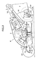
- Fig. 3 is a cross-sectional view taken along line 3-3 in Fig. 2.
- Fig. 4 is an enlarged sectional view taken along line 4-4 in Fig. 2.
- Fig. 5 is an enlarged sectional view taken along line 5-5 in Fig. 2.
- Fig. 6 is an enlarged sectional view taken along line 6-6 in Fig. 2.
- Fig. 7 is a cross-sectional view taken along line 7-7 in Fig. 6.
- an electric lawn mower M has a cutter housing 1 which is also used as a mower frame.
- a pair of left and right front wheels Wf, Wf are arranged at a front portion of this cutter housing 1.
- a pair of left and right rear wheels Wr, Wr are arranged at a rear portion of the cutter housing 1.
- a bowl-shaped housing cover 2 is arranged on an upper face or surface of the cutter housing 1 such that this housing cover 2 can be freely opened and closed.
- a grass bag 3 for storing cut grass is detachably arranged at the rear end of the cutter housing 1.
- a handle 5 for operating the electric lawn mower M is supported by handle stays 4, 4 fixed to left and right rear ends of the cutter housing 1, such that the length of the handle 5 can be freely adjusted.
- a substantially flat motor supporting portion 1 1 is formed in a central portion of the cutter housing 1.
- An electric motor 7 is supported by this motor supporting portion 1 1 through a motor supporting bracket 6.
- the motor supporting bracket 6 is formed with a plate body of approximately a triangular shape and is attached to the motor supporting portion 1 1 of the cutter housing 1 at three attaching portions corresponding to three vertexes of the plate body.
- a bolt 8 inserted into the motor supporting bracket 6 extends through a rubber bush 9 formed in the motor supporting portion 1 1 and is fastened to the motor supporting portion 1 1 by a nut 11 through a washer 10.
- a collar 12 having a predetermined length is arranged between the rubber bush 9 and the bolt 8 to provide a predetermined compressing amount to the rubber bush 9.
- a flange 13 is on the lower face of a motor 7 and is fixed to a center of the motor supporting bracket 6 by four sets of bolts 14, and nuts 15.
- an output shaft 16 of the motor 7 is arranged in a vertical direction and extends downward through the motor supporting bracket 6 and the motor supporting portion 1 1 of the cutter housing 1.
- a cutter 17 having two blades is attached to a lower end of the output shaft 16. The cutter 17 may be replaced with a cutter having two blades in each of the upper and lower portions thereof.
- Front wheel supporting members 18, 18 each formed in a plate shape, are pivotally supported on the left and right sides of a front portion of the cutter housing 1 through swinging shafts 19, 19, such that the front wheel supporting members 18, 18 are freely swung.
- This pair of front wheel supporting members 18, 18 are integrally connected to each other by a connecting member 20.
- the front wheels Wf, Wf are rotatably supported by the front wheel supporting members 18, 18 through axles 21, 21.
- the pair of front wheel supporting members 18, 18 are respectively swung around the swinging shafts 19, 19 and are locked by a locking means (not shown) so that a mower height of the mower body front portion can be arbitrarily adjusted and the clearance between the cutter 17 and the ground can be changed.
- a transmission 22 is mounted on the left side of a rear portion of the cutter housing 1.
- a transmission input shaft 23 extends upward from the transmission 22.
- a driven pulley 24 on transmission input shaft 23 is connected to a drive pulley 25 on the output shaft 16 of the motor 7, through an endless belt 26.
- Rear wheel supporting members 28, 28 each formed in a plate shape, are swingably supported at both ends of transmission output shaft 27, extending from the transmission 22 in left and right directions of the mower body and are integrally connected to each other by a connecting member 29.
- One portion of the connecting member 29 is curved rearwardly to avoid interference with the transmission 22.
- the rear wheels Wr, Wr are rotatably supported by the rear wheel supporting members 28, 28 through axles 30, 30.
- Pinions 32, 32 are fixed to both ends of the transmission output shaft 27 and are respectively engaged with ring gears 31, 31 arranged on inside diameter portions of the rear wheels Wr, Wr.
- a controller 37 for controlling an operation of the motor 7 is attached to a front portion of the motor supporting portion 1 1 of the cutter housing 1, through a controller supporting bracket 34.
- the controller supporting bracket 34 is formed by folding one metal plate.
- the left side of a bottom face of the controller supporting bracket 34 is fastened to the cutter housing 1 by one of the three bolts 8 for fixing the motor supporting bracket 6 to the cutter housing 1.
- the right side of the bottom face of the controller supporting bracket 34 is fixed to the motor supporting bracket 6 by a bolt 35 and a nut 36.
- a pair of flanges 34 1 , 34 1 are formed on both the left and right sides of the controller supporting bracket 34 and are inclined such that these flanges are lowered on their front sides.
- a pair of flanges 37 1 , 37 1 of the controller 37 are overlapped with these flanges 34 1 , 34 1 and are fixed to these flanges 34 1 , 34 1 by four bolts 38.
- the controller 37 is inclined such that the controller 37 is lower on the front side.
- the controller 37 is then mounted to the front portion of the cutter housing 1. Accordingly, it is possible to avoid interference between an upper face of the controller 37 and an inner face of the housing cover 2 while the housing cover 2 is maintained in a smooth shape.
- a central inclining wall 1 2 rises rearward and upward from a rear side of the motor supporting portion 1 1 of the cutter housing 1.
- a rear edge of the central inclining wall 1 2 forms the upper edge of a discharge port 39 formed at a rear end of the cutter housing 1.
- a pair of side portion inclining walls 1 3 , 1 3 are formed on both the left and right sides of the cutter housing 1 and are inclined such that the side portion inclining walls rise rearward.
- a scroll 40 for guiding grass cut by the cutter 17, to the discharge port 39 is formed on the lower faces or surfaces of the motor supporting portion 1 1 , the central inclining wall 1 2 and the pair of side portion inclining walls 1 3 , 1 3 .
- the height of the upper wall of the scroll 40 from the ground is lowest at a front portion of the mower body and is highest at a rear portion of the mower body near the discharge port 39.
- the batteries 41 for providing power to the motor 7, are arranged in a space to the rear of the motor 7.
- the batteries 41 are fixed to the cutter housing 1 through a supporting plate 43 for supporting the lower face of a battery box 42 having an open upper face.
- the batteries 41 are stored in the battery box 42.
- the battery box 42 has a pair of side portion flanges 42 1 , 42 1 projecting from the left and right sides. These side portion flanges 42 1 , 42 1 and the supporting plate 43 are fastened together to the side portion inclining walls 1 3 , 1 3 through two rivets 44 on each of the left and right sides.
- a rear portion of the supporting plate 43 and the rear portion inclining wall 1 2 are fixed to each other by two rivets 45, 45.
- a bottom wall of the battery box 42 and the supporting plate 43 are fixed to each other by two rivets 46, 46 on each of the left and right sides. Furthermore, one pair of side portion flanges 42 1 , 42 1 of the battery box 42 are fixed to the side portion inclining walls 1 3 , 1 3 by two bolts 47, 47, respectively.
- the four batteries 41, stored into the battery box 42, are fixed by a pair of belts 48, 48 on the left and right sides.
- the battery box 42 is supported such that a front portion of a bottom face of the battery box 42 is projected in an upward space of the motor supporting portion 1 1 of the cutter housing 1 (see Fig. 3). Further, the batteries 41 are mounted to the battery box such that the batteries are lowered forward along the central inclining wall 1 2 and the side portion inclining walls 1 3 , 1 3 slantingly lowered forward. Accordingly, while an open area of the discharge port 39 at a terminal end of the scroll 40 is sufficiently large, interference between the batteries 41 and the housing cover 2 is avoided and a front height of the mower body can be held to a low height.
- the batteries 41, the motor 7 and the controller 37 are arranged forward and rearward along a central line of the mower body. Accordingly, it is possible to uniformly load the left side front wheel Wf and rear wheel Wr, and the right side front wheel Wf and rear wheel Wr.
- running directions of the electric lawn mower M are changed, an operator pushes the handle 5 down and raises the front wheels Wf, Wf from the ground.
- the batteries 41 which are heavy objects, are arranged in the vicinity of the rear wheels Wr, Wr, the required pushing-down load on the handle 5 is reduced so that the running directions of the electric lawn mower are easily changed.
- the controller 37 is arranged on the front side with respect to the motor 7 and the batteries 41 are arranged on the rear side. Accordingly, the upward space of the cutter housing 1 is effectively utilized and the mower body can be made compact.
- a hinge bracket 50 is fixed to a rear end of the central inclining wall 1 2 of the cutter housing 1 by rivets 49.
- a hinge shaft 51 extending in left and right directions of the mower body, is supported by arm portions 50 1 , 50 1 extending to an upper portion of the hinge bracket 50. Both left and right ends of the hinge shaft 51 are respectively fitted to shaft holes 2 1 , 2 1 of the rear portion of the housing cover 2 at both left and right ends thereof, so that the housing cover 2 can be freely opened and closed around the hinge shaft 51.
- a pair of springs 52, 52 are wound around the outer circumference of the hinge shaft 51 and biases the housing cover 2 in its opening direction.
- Devices such as the motor 7, the batteries 41, the controller 37, etc., and the harness for connecting these devices, are positioned in the waterproof/dustproof space 55 so that these devices can be reliably protected from rainwater and dust. Further, maintenance work, such as exchange of the batteries 41, can be easily made by only detaching the two bolts 53, 53 and rotating the housing cover 2 around the hinge shaft 51 to open this housing cover 2. Furthermore, the motor 7, the batteries 41, the controller 37, etc. are perfectly covered with the housing cover 2 so that the external appearance of the electric lawn mower becomes smart and is improved in beauty.
- Two engaging portions 50 2 , 50 2 are integrally formed in the above hinge bracket 50. These engaging portions 50 2 , 50 2 are respectively engaged with hook portions 3 1 , 3 1 formed in the grass bag 3 so that the grass bag 3 is mounted on the discharge port 39 of the cutter housing 1.
- a pair of left and right sleeve-shaped portions 54 1 , 54 1 integrally formed at a front end of a discharge port cover 54, are fitted to an outer circumference of the hinge shaft 51.
- the discharge port cover 54 can be vertically swung between an opening position (see Fig. 1) and a closing position. In the opening position, the discharge port cover 54 is swung upward around the hinge shaft 51 and is held above the grass bag 2. In the closing position, when the grass bag 3 is detached, the discharge port 39 is covered with the discharge port cover 54 and a lower end of the discharge port cover 54 is set to a discharge hole.
- the discharge port cover 54 is pivotally supported by utilizing the hinge shaft 51 of the housing cover 2. Accordingly, both the housing cover 2 and the discharge port cover 54 can be pivotally supported by one hinge shaft 51. Therefore, the electric lawn mower M can be made compact and light in weight, and the cost of the electric lawn mower can be reduced, by reducing the number of parts thereof.
- the motor 7 is commonly used to run the electric lawn mower and operate the cutter 17 in the above embodiment. However, separate motors may be respectively arranged to run the electric lawn motor and operate the cutter 17.
- a cutter housing of an electric lawn mower of a walking type is inclined such that the cutter housing rises in a rearward direction.
- a battery is mounted to the upper face of a rear portion of the cutter housing.
- a discharge port for discharging cut grass into a grass bag is formed on a lower face of the rear portion of the cutter housing.
- An opening area of the discharge port is sufficiently maintained by the rearward rising inclination of the cutter housing.
- the battery is set to take a forward inclining orientation and the height of the mower body can be held to a low height. Since the battery is arranged above a rear wheel, the weight of the battery is supported by the rear wheels and the load on the front wheels is reduced so that the running direction of the electric lawn mower can be easily changed.
Landscapes
- Life Sciences & Earth Sciences (AREA)
- Environmental Sciences (AREA)
- Harvester Elements (AREA)
Description
- The present invention relates to an electric lawn mower of a walking type in which a lawn is cut by rotating a cutter or blade arranged on the lower face of a cutter housing, by an electric motor.
- Such an electric lawn mower is well known by specifications of U. S. Patent No. 3,212,244, which corresponds to the preamble of
claim 1, and French Patent No. 2,039,175. - In the electric lawn mower described in the above specification of U. S. Patent No. 3,212,244, the grass cut by the cutter is left on the ground as it is. Therefore, it is necessary to collect the cut grass after the lawn is mowed. The electric lawn mower described in the specification of French Patent No. 2,039,175 has a discharge port for discharging the grass cut by the cutter in a right side portion of the mower body. Therefore, the cut grass can be collected if a grass bag is mounted at this discharge port.
- When the grass bag is arranged on a side portion of the mower body, the grass bag tends to come in contact with obstacles during the lawn mowing. Accordingly, it is desirable to arrange the grass bag at a rear portion of the mower body. The running direction of an electric lawn mower of a walking type, is changed in a state in which a handle is pushed down and front wheels are lifted from the ground. Accordingly, it is desirable to set the position of the center of gravity of the mower body to be close to a rear wheels. Therefore, it is necessary to arrange the battery which is a heavy object, near the rear wheels. However, when the battery is mounted on the rear portion of the mower body and the discharge port for the grass is arranged in the rear portion of the mower body, the overall height of the mower body is increased. In contrast to this, when the overall height of the mower body is reduced, no opening area for the discharge port can be sufficiently maintained.
- Further, the electric lawn mower has an electric motor for driving the cutter, the battery for supplying power to the electric motor, a controller for controlling an operation of the electric motor, etc. Accordingly, it is necessary to arrange a cover for protecting these devices from rainwater and dust. In the electric lawn mower described in the above specification of U. S. Patent No. 3,212,244, a clearance is formed between the cover and the electric motor, or is formed at a lower edge of the cover. Therefore, a problem exists in that the rainwater and the dust cannot be completely stopped. In the electric lawn mower described in the above specification of French Patent No. 2,039,175, the electric motor, etc. are completely covered with the cover, but no structure for opening and closing this cover is considered. Therefore, a problem exists in that it is complicated to open and close the cover to maintain the mower.
- In consideration of the above situations, an object of the present invention is to provide an electric lawn mower in which a battery is mounted to a rear portion of the mower body and a discharge port for grass is arranged in the rear portion of the mower body, wherein the opening area of the discharge port is sufficient in size while the overall height of the mower body is maintained at a low height.
- To achieve the above object, an electric lawn mower according to a first feature of the present invention is an electric lawn mower of a walking type, in which front and rear portions of a cutter housing are respectively supported by front and rear wheels, and a cutter arranged within a scroll formed on a lower face of the cutter housing, is rotated by an electric motor connected to a battery. An upper face or surface of the cutter housing is inclined such that this upper face of the cutter housing rises rearwardly, and a discharge port for discharging the cut grass from the scroll is formed at a rear end of the cutter housing. A battery is mounted on the upper face of a rear portion of the cutter housing.
- In accordance with the above construction, the entire height of the mower body can be maintained to a low height while the opening area of the discharge port is sufficiently large. Further, the battery as a heavy object, is arranged in the vicinity of the rear wheels so that the running direction of the electric lawn mower can be easily changed.
- To achieve the above object, in addition to the first feature, a second feature of the present invention is an electric motor arranged approximately at the center of the upper face of the cutter housing, and a controller for controlling the operation of the electric motor arranged on a front side of the electric motor. The battery is arranged on a rear side of the electric motor.
- In accordance with the above second feature, the upward space of the cutter housing is effectively utilized and the electric lawn mower can be made compact.
- To achieve the above object, in addition to the first feature, a third feature of the present invention is an electric lawn mower of a walking type for cutting a lawn using an electric motor for rotating a cutter arranged on the lower face of a cutter housing. The electric motor, a battery for supplying power to the electric motor, and a controller for controlling an operation of the electric motor are attached to an upper face of the cutter housing. A waterproof/dustproof space is formed between the cutter housing and a housing cover pivotally supported and freely opened and closed so as to cover the upper face of the cutter housing. The electric motor, the battery and the controller are located in this waterproof/dustproof space.
- In accordance with this construction, the electric motor, the battery and the controller can be protected from water and dust. Further, the battery, etc. can be easily exchanged and maintained by opening the housing cover. Furthermore, the electric motor, the battery and the controller are perfectly covered with the housing cover so that the external appearance of the electric lawn mower is smart.
- To achieve the above object, in addition to the third feature, a fourth feature of the present invention is the cutter housing having a discharge port for discharging the grass cut by the cutter to a grass bag. A discharge port cover covers the discharge port so as to freely open and close the discharge port. The housing cover and the discharge port cover are pivotally supported by a common hinge shaft.
- In accordance with this construction, the number of parts is reduced so that cost of the electric lawn mower can be reduced and the mower can be made lightweight and compact.
- The other objects, features and advantages of the present invention will become apparent from explanations of the following preferred embodiment described in detail with reference to the accompanying drawings.
- Fig. 1 is a perspective view of an entire electric lawn mower of an embodiment of the present invention.
- Fig. 2 is a view seen from the direction of
arrow 2 in Fig. 1. - Fig. 3 is a cross-sectional view taken along line 3-3 in Fig. 2.
- Fig. 4 is an enlarged sectional view taken along line 4-4 in Fig. 2.
- Fig. 5 is an enlarged sectional view taken along line 5-5 in Fig. 2.
- Fig. 6 is an enlarged sectional view taken along line 6-6 in Fig. 2.
- Fig. 7 is a cross-sectional view taken along line 7-7 in Fig. 6.
- As shown in Fig. 1, an electric lawn mower M has a
cutter housing 1 which is also used as a mower frame. A pair of left and right front wheels Wf, Wf are arranged at a front portion of thiscutter housing 1. A pair of left and right rear wheels Wr, Wr are arranged at a rear portion of thecutter housing 1. A bowl-shaped housing cover 2 is arranged on an upper face or surface of thecutter housing 1 such that thishousing cover 2 can be freely opened and closed. Agrass bag 3 for storing cut grass is detachably arranged at the rear end of thecutter housing 1. Ahandle 5 for operating the electric lawn mower M, is supported by handle stays 4, 4 fixed to left and right rear ends of thecutter housing 1, such that the length of thehandle 5 can be freely adjusted. - As can be clearly seen from Figs. 2 and 3, a substantially flat
motor supporting portion 11 is formed in a central portion of thecutter housing 1. Anelectric motor 7 is supported by thismotor supporting portion 11 through amotor supporting bracket 6. Themotor supporting bracket 6 is formed with a plate body of approximately a triangular shape and is attached to themotor supporting portion 11 of thecutter housing 1 at three attaching portions corresponding to three vertexes of the plate body. One of these three attaching portions is shown in detail in Fig. 4. Abolt 8 inserted into themotor supporting bracket 6 extends through arubber bush 9 formed in themotor supporting portion 11 and is fastened to themotor supporting portion 11 by anut 11 through awasher 10. Acollar 12 having a predetermined length, is arranged between therubber bush 9 and thebolt 8 to provide a predetermined compressing amount to therubber bush 9. Aflange 13 is on the lower face of amotor 7 and is fixed to a center of themotor supporting bracket 6 by four sets ofbolts 14, and nuts 15. As shown in Fig. 3, anoutput shaft 16 of themotor 7 is arranged in a vertical direction and extends downward through themotor supporting bracket 6 and themotor supporting portion 11 of thecutter housing 1. Acutter 17 having two blades is attached to a lower end of theoutput shaft 16. Thecutter 17 may be replaced with a cutter having two blades in each of the upper and lower portions thereof. - Front
wheel supporting members cutter housing 1 through swingingshafts wheel supporting members wheel supporting members member 20. The front wheels Wf, Wf are rotatably supported by the frontwheel supporting members axles wheel supporting members shafts cutter 17 and the ground can be changed. - A transmission 22 is mounted on the left side of a rear portion of the
cutter housing 1. Atransmission input shaft 23 extends upward from the transmission 22. A drivenpulley 24 ontransmission input shaft 23 is connected to a drivepulley 25 on theoutput shaft 16 of themotor 7, through anendless belt 26. Rearwheel supporting members transmission output shaft 27, extending from the transmission 22 in left and right directions of the mower body and are integrally connected to each other by a connectingmember 29. One portion of the connectingmember 29 is curved rearwardly to avoid interference with the transmission 22. The rear wheels Wr, Wr are rotatably supported by the rearwheel supporting members axles Pinions transmission output shaft 27 and are respectively engaged with ring gears 31, 31 arranged on inside diameter portions of the rear wheels Wr, Wr. - Accordingly, rotation of the
output shaft 16 of themotor 7 is transmitted to the ring gears 31, 31 through thedrive pulley 25, theendless belt 26, the drivenpulley 24, thetransmission input shaft 23, the transmission 22, thetransmission output shaft 27 and thepinions wheel supporting members member 29, are swung around thetransmission output shaft 27 and are locked by a locking means (not shown) so that the mower height of the mower body rear portion is arbitrarily adjusted and the clearance between thecutter 17 and the ground can be changed. At this time, no relation in engagement between thepinions motor 7 can be transmitted to the rear wheels Wr, Wr without any problem. - As can be clearly seen from Figs. 2, 3 and 5, a
controller 37 for controlling an operation of themotor 7, is attached to a front portion of themotor supporting portion 11 of thecutter housing 1, through acontroller supporting bracket 34. Thecontroller supporting bracket 34 is formed by folding one metal plate. The left side of a bottom face of thecontroller supporting bracket 34 is fastened to thecutter housing 1 by one of the threebolts 8 for fixing themotor supporting bracket 6 to thecutter housing 1. The right side of the bottom face of thecontroller supporting bracket 34 is fixed to themotor supporting bracket 6 by abolt 35 and anut 36. - A pair of
flanges controller supporting bracket 34 and are inclined such that these flanges are lowered on their front sides. A pair offlanges controller 37 are overlapped with theseflanges flanges bolts 38. Thus, thecontroller 37 is inclined such that thecontroller 37 is lower on the front side. Thecontroller 37 is then mounted to the front portion of thecutter housing 1. Accordingly, it is possible to avoid interference between an upper face of thecontroller 37 and an inner face of thehousing cover 2 while thehousing cover 2 is maintained in a smooth shape. - As can be clearly seen from Figs. 2 and 3, a
central inclining wall 12 rises rearward and upward from a rear side of themotor supporting portion 11 of thecutter housing 1. A rear edge of thecentral inclining wall 12 forms the upper edge of adischarge port 39 formed at a rear end of thecutter housing 1. A pair of sideportion inclining walls cutter housing 1 and are inclined such that the side portion inclining walls rise rearward. Ascroll 40 for guiding grass cut by thecutter 17, to thedischarge port 39 is formed on the lower faces or surfaces of themotor supporting portion 11, thecentral inclining wall 12 and the pair of sideportion inclining walls scroll 40 from the ground is lowest at a front portion of the mower body and is highest at a rear portion of the mower body near thedischarge port 39. - Four
batteries 41 for providing power to themotor 7, are arranged in a space to the rear of themotor 7. Thebatteries 41 are fixed to thecutter housing 1 through a supportingplate 43 for supporting the lower face of abattery box 42 having an open upper face. Thebatteries 41 are stored in thebattery box 42. Thebattery box 42 has a pair ofside portion flanges side portion flanges plate 43 are fastened together to the sideportion inclining walls rivets 44 on each of the left and right sides. A rear portion of the supportingplate 43 and the rearportion inclining wall 12 are fixed to each other by two rivets 45, 45. Further, a bottom wall of thebattery box 42 and the supportingplate 43 are fixed to each other by tworivets side portion flanges battery box 42 are fixed to the sideportion inclining walls bolts batteries 41, stored into thebattery box 42, are fixed by a pair ofbelts - The
battery box 42 is supported such that a front portion of a bottom face of thebattery box 42 is projected in an upward space of themotor supporting portion 11 of the cutter housing 1 (see Fig. 3). Further, thebatteries 41 are mounted to the battery box such that the batteries are lowered forward along thecentral inclining wall 12 and the sideportion inclining walls discharge port 39 at a terminal end of thescroll 40 is sufficiently large, interference between thebatteries 41 and thehousing cover 2 is avoided and a front height of the mower body can be held to a low height. - The
batteries 41, themotor 7 and thecontroller 37 are arranged forward and rearward along a central line of the mower body. Accordingly, it is possible to uniformly load the left side front wheel Wf and rear wheel Wr, and the right side front wheel Wf and rear wheel Wr. When running directions of the electric lawn mower M are changed, an operator pushes thehandle 5 down and raises the front wheels Wf, Wf from the ground. However, since thebatteries 41, which are heavy objects, are arranged in the vicinity of the rear wheels Wr, Wr, the required pushing-down load on thehandle 5 is reduced so that the running directions of the electric lawn mower are easily changed. Further, thecontroller 37 is arranged on the front side with respect to themotor 7 and thebatteries 41 are arranged on the rear side. Accordingly, the upward space of thecutter housing 1 is effectively utilized and the mower body can be made compact. - As can be clearly seen from Figs. 6 and 7, a
hinge bracket 50 is fixed to a rear end of thecentral inclining wall 12 of thecutter housing 1 byrivets 49. Ahinge shaft 51 extending in left and right directions of the mower body, is supported byarm portions hinge bracket 50. Both left and right ends of thehinge shaft 51 are respectively fitted toshaft holes housing cover 2 at both left and right ends thereof, so that thehousing cover 2 can be freely opened and closed around thehinge shaft 51. A pair ofsprings hinge shaft 51 and biases thehousing cover 2 in its opening direction. Accordingly, when thehousing cover 2 is manually raised and opened, the applied load is reduced. Twobolts housing cover 2 are respectively screwed intobolt holes cutter housing 1 so that thehousing cover 2 is fixed in a closed position (see Figs. 2 and 3). - A lower edge of the
housing cover 2 fixed in the closed position, is closely attached and sealed to an upper face of thecutter housing 1. Therefore, a substantially sealed waterproof/dustproof space 55 is formed between thehousing cover 2 and thecutter housing 1. Devices such as themotor 7, thebatteries 41, thecontroller 37, etc., and the harness for connecting these devices, are positioned in the waterproof/dustproof space 55 so that these devices can be reliably protected from rainwater and dust. Further, maintenance work, such as exchange of thebatteries 41, can be easily made by only detaching the twobolts housing cover 2 around thehinge shaft 51 to open thishousing cover 2. Furthermore, themotor 7, thebatteries 41, thecontroller 37, etc. are perfectly covered with thehousing cover 2 so that the external appearance of the electric lawn mower becomes smart and is improved in beauty. - Two
engaging portions above hinge bracket 50. These engagingportions hook portions grass bag 3 so that thegrass bag 3 is mounted on thedischarge port 39 of thecutter housing 1. A pair of left and right sleeve-shapedportions discharge port cover 54, are fitted to an outer circumference of thehinge shaft 51. The discharge port cover 54 can be vertically swung between an opening position (see Fig. 1) and a closing position. In the opening position, thedischarge port cover 54 is swung upward around thehinge shaft 51 and is held above thegrass bag 2. In the closing position, when thegrass bag 3 is detached, thedischarge port 39 is covered with thedischarge port cover 54 and a lower end of thedischarge port cover 54 is set to a discharge hole. - Thus, the
discharge port cover 54 is pivotally supported by utilizing thehinge shaft 51 of thehousing cover 2. Accordingly, both thehousing cover 2 and the discharge port cover 54 can be pivotally supported by onehinge shaft 51. Therefore, the electric lawn mower M can be made compact and light in weight, and the cost of the electric lawn mower can be reduced, by reducing the number of parts thereof. - The
motor 7 is commonly used to run the electric lawn mower and operate thecutter 17 in the above embodiment. However, separate motors may be respectively arranged to run the electric lawn motor and operate thecutter 17. - The embodiment of the present invention has been described in detail as mentioned above, but the present invention can be modified in various kinds of designs within a range not departing from features of the present invention as defined by the scope of the claims.
- A cutter housing of an electric lawn mower of a walking type is inclined such that the cutter housing rises in a rearward direction. A battery is mounted to the upper face of a rear portion of the cutter housing. A discharge port for discharging cut grass into a grass bag is formed on a lower face of the rear portion of the cutter housing. An opening area of the discharge port is sufficiently maintained by the rearward rising inclination of the cutter housing. The battery is set to take a forward inclining orientation and the height of the mower body can be held to a low height. Since the battery is arranged above a rear wheel, the weight of the battery is supported by the rear wheels and the load on the front wheels is reduced so that the running direction of the electric lawn mower can be easily changed.
Claims (5)
- A walking-type electric lawn mower (M), comprising:characterized in that said cutter housing (1) has an inclined upper face (12, 13) rising in a rearward direction when viewed in a travel direction of said mower (M), said discharge port (39) being formed at a rear end of said housing (1), said battery means (41) being mounted on a rear portion of said inclined upper face (12, 13) of said housing (1).a cutter housing (1),front wheels (Wf) and rear wheels (Wr) supported on said housing (1),a grass cutter (17) disposed in said housing (1),an electric motor (7) mounted on said housing (1) for rotating said cutter (17),battery means (41) mounted on said housing (1) for providing power to said electric motor (7), anda discharge port (39) for discharging cut grass from said cutter housing (1),
- An electric lawn mower as claimed in Claim 1, wherein said housing includes a scroll formed on the lower face thereof, and wherein said cutter is positioned in said scroll.
- An electric lawn mower as claimed in Claim 1, wherein said electric motor is positioned at the approximate center of the upper face of said cutter housing, and said battery is positioned on the rear side of said electric motor, and wherein said lawn mower includes a controller for controlling the operation of said electric motor, said controller being positioned on the front side of said electric motor.
- An electric lawn mower as claimed in Claim 1 wherein said electric motor, the battery for supplying power to the electric motor, and a controller for controlling an operation of the electric motor are attached to the upper face of the cutter housing, and a waterproof/dustproof space is formed between said cutter housing and a housing cover pivotally supported and freely opened and closed so as to cover the upper face of the cutter housing; and said electric motor, the battery and the controller are stored into this waterproof/dustproof pace.
- An electric lawn mower as claimed in Claim 4, wherein said cutter housing includes a discharge port for discharging the grass cut by said cutter into a grass bag, a discharge port cover for covering said discharge port, and a pivot shaft for pivotally mounting said housing cover and said discharge port cover, such that said housing and said discharge port may be opened and closed by the respective rotation of said housing cover and said discharge port cover around said pivot shaft.
Applications Claiming Priority (3)
| Application Number | Priority Date | Filing Date | Title |
|---|---|---|---|
| JP24475496A JP3160759B2 (en) | 1996-09-17 | 1996-09-17 | Electric lawn mower |
| JP244754/96 | 1996-09-17 | ||
| JP24475496 | 1996-09-17 |
Publications (3)
| Publication Number | Publication Date |
|---|---|
| EP0829196A2 EP0829196A2 (en) | 1998-03-18 |
| EP0829196A3 EP0829196A3 (en) | 1998-05-20 |
| EP0829196B1 true EP0829196B1 (en) | 2002-01-30 |
Family
ID=17123408
Family Applications (1)
| Application Number | Title | Priority Date | Filing Date |
|---|---|---|---|
| EP97116022A Expired - Lifetime EP0829196B1 (en) | 1996-09-17 | 1997-09-15 | Electric lawn mower |
Country Status (4)
| Country | Link |
|---|---|
| US (1) | US5910091A (en) |
| EP (1) | EP0829196B1 (en) |
| JP (1) | JP3160759B2 (en) |
| DE (1) | DE69710142T2 (en) |
Families Citing this family (94)
| Publication number | Priority date | Publication date | Assignee | Title |
|---|---|---|---|---|
| JP2000108699A (en) * | 1998-10-08 | 2000-04-18 | Kanzaki Kokyukoki Mfg Co Ltd | Axle driving device |
| USD458277S1 (en) * | 1999-03-18 | 2002-06-04 | Black & Decker Inc. | Lawn mower |
| US6195969B1 (en) * | 1999-04-03 | 2001-03-06 | YILMAZ GüRSEL GEORGE | Apparatus for multifunctional lawn mower and multidirectional shell |
| USD456030S1 (en) | 2000-08-29 | 2002-04-23 | Honda Giken Kogyo Kabushiki Kaisha | Lawn mower |
| US6427429B1 (en) | 2001-04-23 | 2002-08-06 | William Brabenec | Multiple string lawnmower |
| JP3776773B2 (en) * | 2001-08-22 | 2006-05-17 | 本田技研工業株式会社 | Electric lawn mower |
| USD497918S1 (en) | 2003-02-14 | 2004-11-02 | Honda Giken Kogyo Kabushiki Kaisha | Lawn mower |
| USD489734S1 (en) | 2003-06-10 | 2004-05-11 | Macauto Industrial Co., Ltd. | Lawn mower |
| USD544501S1 (en) * | 2006-04-26 | 2007-06-12 | Hsin-Chih Chung Lee | Petrol lawn mower |
| GB0615241D0 (en) | 2006-08-01 | 2006-09-06 | Bosch Gmbh Robert | Lawn-care apparatus |
| US8732896B2 (en) | 2006-10-17 | 2014-05-27 | Mtd Products Inc | Hybrid electric cleaning device |
| US7479754B2 (en) | 2006-10-17 | 2009-01-20 | Desa Ip Llc | Hybrid electric lawnmower |
| US7728534B2 (en) | 2006-10-17 | 2010-06-01 | Mtd Products Inc | Hybrid electric lawnmower |
| WO2008048618A2 (en) | 2006-10-17 | 2008-04-24 | Desa Ip. Llc | Hybrid electric device |
| US8076873B1 (en) | 2007-06-01 | 2011-12-13 | Mtd Products Inc | Hybrid outdoor power equipment |
| USD581951S1 (en) * | 2007-10-01 | 2008-12-02 | Desa Ip, Llc | Hybrid electric lawnmower |
| JP5239312B2 (en) * | 2007-11-22 | 2013-07-17 | 日立工機株式会社 | Lawn mower |
| USD600254S1 (en) * | 2008-09-29 | 2009-09-15 | Neuton, Inc. | Lawn mower |
| USD605667S1 (en) * | 2008-09-29 | 2009-12-08 | Neuton, Inc. | Lawn mower |
| USD626971S1 (en) * | 2008-09-29 | 2010-11-09 | Neuton, Inc. | Lawn mower |
| US8037669B2 (en) * | 2009-04-28 | 2011-10-18 | Husqvarna Consumer Outdoor Products N.A., Inc. | Baffle based battery housing |
| USD620030S1 (en) * | 2009-09-11 | 2010-07-20 | Black & Decker Inc. | Mower |
| USD620029S1 (en) * | 2009-09-11 | 2010-07-20 | Black & Decker Inc. | Mower |
| US8769917B1 (en) * | 2009-10-29 | 2014-07-08 | Jeffrey E. Howell | Battery-operated compact riding rotary mower |
| JP5371861B2 (en) * | 2010-03-30 | 2013-12-18 | 本田技研工業株式会社 | Walking type work machine |
| USD627372S1 (en) * | 2010-05-28 | 2010-11-16 | Black & Decker Inc. | Mower |
| US8336282B2 (en) * | 2010-07-28 | 2012-12-25 | Deere & Company | Robotic mower housing |
| USD646698S1 (en) * | 2010-09-04 | 2011-10-11 | Chervon Limited | Lawn mower |
| EP2499894B1 (en) * | 2011-03-14 | 2014-07-02 | Robert Bosch GmbH | Lawnmowers |
| JP2013000028A (en) | 2011-06-14 | 2013-01-07 | Makita Corp | Electric mower |
| JP5689753B2 (en) | 2011-06-14 | 2015-03-25 | 株式会社マキタ | Electric lawn mower |
| JP5912305B2 (en) | 2011-06-14 | 2016-04-27 | 株式会社マキタ | Electric lawn mower |
| JP5694065B2 (en) | 2011-06-14 | 2015-04-01 | 株式会社マキタ | Electric lawn mower |
| JP5805437B2 (en) | 2011-06-14 | 2015-11-04 | 株式会社マキタ | Electric lawn mower |
| JP5752532B2 (en) * | 2011-09-02 | 2015-07-22 | ヤンマー株式会社 | Electric work vehicle |
| WO2012176350A1 (en) * | 2011-06-22 | 2012-12-27 | ヤンマー株式会社 | Electric work machine |
| US8727233B2 (en) | 2011-10-17 | 2014-05-20 | Champion Power Equipment, Inc. | Pressure spray washer and control |
| US8733072B2 (en) | 2011-11-04 | 2014-05-27 | Briggs & Stratton Corporation | Starter system for an engine |
| US9127658B2 (en) | 2011-11-04 | 2015-09-08 | Briggs & Stratton Corporation | Internal combustion engine including starting system powered by lithium-ion battery |
| US8857138B2 (en) | 2011-11-04 | 2014-10-14 | Briggs & Stratton Corporation | Starter system for an engine |
| JP5808259B2 (en) * | 2012-01-17 | 2015-11-10 | 株式会社クボタ | Walking mower |
| JP5808258B2 (en) * | 2012-01-17 | 2015-11-10 | 株式会社クボタ | Walking mower |
| EP2636295B1 (en) * | 2012-03-07 | 2014-09-10 | Robert Bosch GmbH | Lawn-care apparatus |
| USD648754S1 (en) * | 2012-11-05 | 2011-11-15 | Honda Motor Co., Ltd. | Lawn mower |
| JP6092006B2 (en) * | 2013-06-03 | 2017-03-08 | 株式会社クボタ | Mower |
| JP6092005B2 (en) * | 2013-06-03 | 2017-03-08 | 株式会社クボタ | Mower |
| JP6034752B2 (en) * | 2013-06-11 | 2016-11-30 | 株式会社クボタ | Walking mower |
| JP6088914B2 (en) * | 2013-06-11 | 2017-03-01 | 株式会社クボタ | Walking mower |
| US10130962B2 (en) | 2013-10-10 | 2018-11-20 | Briggs & Stratton Corporation | Wirelessly controlled trigger start and chemical tank change-over for pressure washers |
| US10181590B2 (en) | 2014-03-06 | 2019-01-15 | Briggs & Stratton Corporation | Rechargeable battery system for replacement of lead-acid battery |
| US9699966B2 (en) * | 2014-10-24 | 2017-07-11 | Deere & Company | Mower deck spindle cover |
| AU2014411082B2 (en) * | 2014-11-14 | 2018-12-13 | Techtronic Industries Company Limited | Electric lawn mower |
| CN105794388A (en) * | 2014-12-30 | 2016-07-27 | 南京德朔实业有限公司 | Power tool |
| CN104584767B (en) * | 2015-01-06 | 2016-08-24 | 中国矿业大学 | Spiral automatic mower |
| CN106258180B (en) * | 2015-05-20 | 2019-03-08 | 南京德朔实业有限公司 | walk mower |
| FR3039355B1 (en) * | 2015-07-27 | 2017-07-14 | Pellenc Sa | ELECTRIC MOWER WITH MULTIPLE BLADES |
| JP6546289B2 (en) * | 2015-12-24 | 2019-07-17 | 本田技研工業株式会社 | Lawn mower |
| CN105835011A (en) * | 2016-05-31 | 2016-08-10 | 常州格力博有限公司 | Safety structure for gardening tool and gardening tool |
| USD795181S1 (en) | 2016-06-15 | 2017-08-22 | Briggs & Stratton Corporation | Battery |
| US11172607B2 (en) | 2016-06-30 | 2021-11-16 | Tti (Macao Commercial Offshore) Limited | Autonomous lawn mower and a system for navigating thereof |
| CN109416543B (en) | 2016-06-30 | 2022-11-08 | 创科(澳门离岸商业服务)有限公司 | Autonomous mower and navigation system thereof |
| EP3549432B1 (en) * | 2016-11-30 | 2021-01-27 | Honda Motor Co., Ltd. | Electric work machine |
| JP6559113B2 (en) * | 2016-11-30 | 2019-08-14 | 本田技研工業株式会社 | Electric lawn mower |
| USD834071S1 (en) * | 2017-03-14 | 2018-11-20 | Husqvarna Ab | Lawnmower |
| USD834072S1 (en) * | 2017-03-14 | 2018-11-20 | Husqvarna Ab | Lawnmower |
| USD833486S1 (en) * | 2017-09-07 | 2018-11-13 | The Toro Company | Lawn mower powerhead |
| USD831076S1 (en) * | 2017-09-27 | 2018-10-16 | Sunrise Global Marketing LLC | Lawnmower powerhead |
| USD853453S1 (en) * | 2017-09-27 | 2019-07-09 | Sunrise Global Marketing LLC | Dual blade lawnmower |
| DE202018006581U1 (en) | 2017-09-27 | 2021-08-18 | Positec Power Tools (Suzhou) Co., Ltd. | Automotive device and associated automatic working system |
| US11394216B2 (en) | 2017-10-27 | 2022-07-19 | Positec Power Tools (Suzhou) Co., Ltd. | Automatic working system |
| DE112017008227B4 (en) * | 2017-11-22 | 2024-02-29 | Honda Motor Co., Ltd. | working machine |
| US11490566B2 (en) * | 2019-04-08 | 2022-11-08 | Honda Motor Co., Ltd. | Apparatus and method for cooling lawnmower components |
| US12382865B2 (en) * | 2019-08-07 | 2025-08-12 | Honda Motor Co., Ltd. | Work machine with housing and case |
| JP1690868S (en) * | 2021-02-11 | 2021-07-26 | ||
| USD1048109S1 (en) * | 2021-06-09 | 2024-10-22 | Jiangsu Dongcheng Tools Technology Co., Ltd. | Lawn mower |
| USD964429S1 (en) * | 2021-07-07 | 2022-09-20 | Photonix Corp | Solar lawnmower |
| CN113557842A (en) * | 2021-07-09 | 2021-10-29 | 张宝斌 | Replaceable blade structure for lawn machine |
| CN222515607U (en) | 2021-08-10 | 2025-02-25 | 米沃奇电动工具公司 | Mower and mower accessory |
| USD980875S1 (en) * | 2021-08-10 | 2023-03-14 | Milwaukee Electric Tool Corporation | Lawn mower |
| WO2023018837A1 (en) | 2021-08-10 | 2023-02-16 | Milwaukee Electric Tool Corporation | Lawnmower including electrostatic discharge |
| USD1008315S1 (en) * | 2022-05-11 | 2023-12-19 | The Toro Company | Lawn mower bumper |
| JP1737779S (en) * | 2022-07-20 | 2023-02-28 | lawn mower | |
| USD1044878S1 (en) * | 2022-08-08 | 2024-10-01 | Shanghai Suntek Technology Co., Ltd. | Lawn mower |
| USD1037319S1 (en) * | 2022-08-25 | 2024-07-30 | Nanjing Chervon Industry Co., Ltd. | Lawn mower |
| USD1059425S1 (en) | 2022-08-26 | 2025-01-28 | The Toro Company | Lawn mower powerhead |
| USD978921S1 (en) * | 2022-09-06 | 2023-02-21 | The Toro Company | Lawn mower housing |
| USD1044879S1 (en) * | 2022-09-09 | 2024-10-01 | Shanghai Suntek Technology Co., Ltd. | Lawn mower |
| USD1042554S1 (en) * | 2023-02-20 | 2024-09-17 | Zhejiang Guyuehu Industry and Trade Co., Ltd. | Lawn mower |
| USD1044880S1 (en) | 2023-02-20 | 2024-10-01 | The Toro Company | Lawn mower housing |
| USD1072000S1 (en) * | 2023-02-23 | 2025-04-22 | Positec Power Tools (Suzhou) Co., Ltd. | Lawn mower battery pack cover |
| USD1073744S1 (en) * | 2023-09-07 | 2025-05-06 | Greenworks (Jiangsu) Co. Ltd. | Walk behind mower |
| USD1092567S1 (en) * | 2023-10-17 | 2025-09-09 | Black & Decker Inc. | Lawn mower |
| USD1099981S1 (en) * | 2024-07-01 | 2025-10-28 | Ningbo Winner Electric Appliances Co., Ltd | Lawn comber |
| USD1100995S1 (en) * | 2024-07-09 | 2025-11-04 | Black & Decker Inc. | Mower |
Family Cites Families (9)
| Publication number | Priority date | Publication date | Assignee | Title |
|---|---|---|---|---|
| US3212244A (en) * | 1963-03-07 | 1965-10-19 | Barton M Wilgus | Power mower |
| BE742969A (en) * | 1969-04-15 | 1970-05-14 | ||
| US4326370A (en) * | 1979-05-31 | 1982-04-27 | The Toro Company | Rotary lawn mower |
| FR2573954B1 (en) * | 1984-11-30 | 1990-09-07 | Honda Motor Co Ltd | HOUSING FOR THE CUTTING DEVICE OF A MOTORIZED LAWN MOWER |
| US4930300A (en) * | 1989-06-02 | 1990-06-05 | Deere & Company | Lawn mower battery mounting |
| US5203147A (en) * | 1992-01-22 | 1993-04-20 | Ryobi Motor Products Corp. | Lawn mower activation switch |
| US5606851A (en) * | 1993-09-22 | 1997-03-04 | Briggs & Stratton Corporation | Battery-powered lawn cutting system |
| JPH09201126A (en) * | 1995-11-24 | 1997-08-05 | Honda Motor Co Ltd | Electric lawn mower |
| US5727372A (en) * | 1996-05-30 | 1998-03-17 | The Toro Company | On-board charging system for electric lawn mower |
-
1996
- 1996-09-17 JP JP24475496A patent/JP3160759B2/en not_active Expired - Fee Related
-
1997
- 1997-09-15 EP EP97116022A patent/EP0829196B1/en not_active Expired - Lifetime
- 1997-09-15 DE DE69710142T patent/DE69710142T2/en not_active Expired - Lifetime
- 1997-09-16 US US08/931,412 patent/US5910091A/en not_active Expired - Lifetime
Also Published As
| Publication number | Publication date |
|---|---|
| DE69710142D1 (en) | 2002-03-14 |
| EP0829196A3 (en) | 1998-05-20 |
| JP3160759B2 (en) | 2001-04-25 |
| US5910091A (en) | 1999-06-08 |
| JPH1084739A (en) | 1998-04-07 |
| EP0829196A2 (en) | 1998-03-18 |
| DE69710142T2 (en) | 2002-06-06 |
Similar Documents
| Publication | Publication Date | Title |
|---|---|---|
| US5910091A (en) | Electric lawn mower | |
| US5463853A (en) | Lawnmower with adjustable side cutters | |
| EP3295784B1 (en) | Mid-mount riding grass mower | |
| EP3741197B1 (en) | Mower unit | |
| US5953890A (en) | Electric lawn mower | |
| KR20110110036A (en) | Lawn mower | |
| JP3160758B2 (en) | Electric lawn mower | |
| CN218680092U (en) | Mowing tractor | |
| JP3382488B2 (en) | Riding mower | |
| CN116114474A (en) | Riding type mowing equipment | |
| CN221468369U (en) | Mower and mowing system | |
| EP0803179B1 (en) | Walking-type lawn mower with battery support structure | |
| CN218892647U (en) | Saddle-riding type vehicle | |
| CN116114460A (en) | Riding type mowing equipment | |
| JP2022034318A (en) | Riding type mower | |
| JP3406170B2 (en) | Riding mower | |
| JP3089158B2 (en) | Moore | |
| JPH0555086B2 (en) | ||
| EP4335278A1 (en) | Ride-on lawn mowing apparatus | |
| CN219719119U (en) | Mower shell with automatic cover opening function | |
| EP3957152B1 (en) | Riding grass mower | |
| JPH0345546Y2 (en) | ||
| JP2807330B2 (en) | Rear discharge type riding lawn mower | |
| JPH0424901Y2 (en) | ||
| JPH0142991Y2 (en) |
Legal Events
| Date | Code | Title | Description |
|---|---|---|---|
| PUAI | Public reference made under article 153(3) epc to a published international application that has entered the european phase |
Free format text: ORIGINAL CODE: 0009012 |
|
| AK | Designated contracting states |
Kind code of ref document: A2 Designated state(s): DE FR IT |
|
| PUAL | Search report despatched |
Free format text: ORIGINAL CODE: 0009013 |
|
| AK | Designated contracting states |
Kind code of ref document: A3 Designated state(s): AT BE CH DE DK ES FI FR GB GR IE IT LI LU MC NL PT SE |
|
| 17P | Request for examination filed |
Effective date: 19980520 |
|
| AKX | Designation fees paid |
Free format text: DE FR IT |
|
| RBV | Designated contracting states (corrected) |
Designated state(s): DE FR IT |
|
| 17Q | First examination report despatched |
Effective date: 20000309 |
|
| GRAG | Despatch of communication of intention to grant |
Free format text: ORIGINAL CODE: EPIDOS AGRA |
|
| GRAG | Despatch of communication of intention to grant |
Free format text: ORIGINAL CODE: EPIDOS AGRA |
|
| GRAH | Despatch of communication of intention to grant a patent |
Free format text: ORIGINAL CODE: EPIDOS IGRA |
|
| GRAH | Despatch of communication of intention to grant a patent |
Free format text: ORIGINAL CODE: EPIDOS IGRA |
|
| GRAA | (expected) grant |
Free format text: ORIGINAL CODE: 0009210 |
|
| AK | Designated contracting states |
Kind code of ref document: B1 Designated state(s): DE FR IT |
|
| REF | Corresponds to: |
Ref document number: 69710142 Country of ref document: DE Date of ref document: 20020314 |
|
| ET | Fr: translation filed | ||
| PLBE | No opposition filed within time limit |
Free format text: ORIGINAL CODE: 0009261 |
|
| STAA | Information on the status of an ep patent application or granted ep patent |
Free format text: STATUS: NO OPPOSITION FILED WITHIN TIME LIMIT |
|
| 26N | No opposition filed | ||
| PGFP | Annual fee paid to national office [announced via postgrant information from national office to epo] |
Ref country code: DE Payment date: 20130911 Year of fee payment: 17 |
|
| PGFP | Annual fee paid to national office [announced via postgrant information from national office to epo] |
Ref country code: FR Payment date: 20130910 Year of fee payment: 17 |
|
| PGFP | Annual fee paid to national office [announced via postgrant information from national office to epo] |
Ref country code: IT Payment date: 20130912 Year of fee payment: 17 |
|
| REG | Reference to a national code |
Ref country code: DE Ref legal event code: R119 Ref document number: 69710142 Country of ref document: DE |
|
| REG | Reference to a national code |
Ref country code: DE Ref legal event code: R119 Ref document number: 69710142 Country of ref document: DE Effective date: 20150401 |
|
| REG | Reference to a national code |
Ref country code: FR Ref legal event code: ST Effective date: 20150529 |
|
| PG25 | Lapsed in a contracting state [announced via postgrant information from national office to epo] |
Ref country code: DE Free format text: LAPSE BECAUSE OF NON-PAYMENT OF DUE FEES Effective date: 20150401 |
|
| PG25 | Lapsed in a contracting state [announced via postgrant information from national office to epo] |
Ref country code: FR Free format text: LAPSE BECAUSE OF NON-PAYMENT OF DUE FEES Effective date: 20140930 Ref country code: IT Free format text: LAPSE BECAUSE OF NON-PAYMENT OF DUE FEES Effective date: 20140915 |