EP0828081B1 - Pump and medium circulation apparatus - Google Patents
Pump and medium circulation apparatus Download PDFInfo
- Publication number
- EP0828081B1 EP0828081B1 EP97115373A EP97115373A EP0828081B1 EP 0828081 B1 EP0828081 B1 EP 0828081B1 EP 97115373 A EP97115373 A EP 97115373A EP 97115373 A EP97115373 A EP 97115373A EP 0828081 B1 EP0828081 B1 EP 0828081B1
- Authority
- EP
- European Patent Office
- Prior art keywords
- rotor
- medium
- pump
- solution
- circulation apparatus
- Prior art date
- Legal status (The legal status is an assumption and is not a legal conclusion. Google has not performed a legal analysis and makes no representation as to the accuracy of the status listed.)
- Expired - Lifetime
Links
- 230000008859 change Effects 0.000 claims description 35
- 230000008961 swelling Effects 0.000 claims description 34
- 229910052751 metal Inorganic materials 0.000 claims description 28
- 239000002184 metal Substances 0.000 claims description 28
- 238000001816 cooling Methods 0.000 claims description 24
- 239000005011 phenolic resin Substances 0.000 claims description 24
- 229920003002 synthetic resin Polymers 0.000 claims description 20
- 239000000057 synthetic resin Substances 0.000 claims description 20
- XLYOFNOQVPJJNP-UHFFFAOYSA-N water Substances O XLYOFNOQVPJJNP-UHFFFAOYSA-N 0.000 claims description 18
- LFQSCWFLJHTTHZ-UHFFFAOYSA-N Ethanol Chemical compound CCO LFQSCWFLJHTTHZ-UHFFFAOYSA-N 0.000 claims description 15
- YCKRFDGAMUMZLT-UHFFFAOYSA-N Fluorine atom Chemical compound [F] YCKRFDGAMUMZLT-UHFFFAOYSA-N 0.000 claims description 13
- 229910052731 fluorine Inorganic materials 0.000 claims description 13
- 239000011737 fluorine Substances 0.000 claims description 13
- -1 heterocyclic organic compound Chemical class 0.000 claims description 11
- 239000000243 solution Substances 0.000 description 49
- 239000003507 refrigerant Substances 0.000 description 40
- 239000006096 absorbing agent Substances 0.000 description 22
- 239000012267 brine Substances 0.000 description 13
- HPALAKNZSZLMCH-UHFFFAOYSA-M sodium;chloride;hydrate Chemical compound O.[Na+].[Cl-] HPALAKNZSZLMCH-UHFFFAOYSA-M 0.000 description 13
- 239000002250 absorbent Substances 0.000 description 11
- 230000002745 absorbent Effects 0.000 description 11
- 230000007797 corrosion Effects 0.000 description 10
- 238000005260 corrosion Methods 0.000 description 10
- 230000007423 decrease Effects 0.000 description 8
- 238000003754 machining Methods 0.000 description 7
- 239000000463 material Substances 0.000 description 7
- 238000005192 partition Methods 0.000 description 7
- 238000001704 evaporation Methods 0.000 description 4
- 230000008020 evaporation Effects 0.000 description 4
- 238000002474 experimental method Methods 0.000 description 4
- 229920001342 Bakelite® Polymers 0.000 description 3
- 238000010521 absorption reaction Methods 0.000 description 3
- 230000009471 action Effects 0.000 description 3
- 238000009835 boiling Methods 0.000 description 3
- 230000000052 comparative effect Effects 0.000 description 3
- 230000003247 decreasing effect Effects 0.000 description 3
- 239000000945 filler Substances 0.000 description 3
- 150000002739 metals Chemical class 0.000 description 3
- 239000004033 plastic Substances 0.000 description 3
- 238000005086 pumping Methods 0.000 description 3
- 229920005989 resin Polymers 0.000 description 3
- 239000011347 resin Substances 0.000 description 3
- 239000000126 substance Substances 0.000 description 3
- NFJSYLMJBNUDNG-UHFFFAOYSA-N 1,3-dipropylimidazolidin-2-one Chemical compound CCCN1CCN(CCC)C1=O NFJSYLMJBNUDNG-UHFFFAOYSA-N 0.000 description 2
- 229910000838 Al alloy Inorganic materials 0.000 description 2
- 125000000217 alkyl group Chemical group 0.000 description 2
- 125000004432 carbon atom Chemical group C* 0.000 description 2
- 238000002485 combustion reaction Methods 0.000 description 2
- 239000002826 coolant Substances 0.000 description 2
- 239000000446 fuel Substances 0.000 description 2
- ZZUFCTLCJUWOSV-UHFFFAOYSA-N furosemide Chemical compound C1=C(Cl)C(S(=O)(=O)N)=CC(C(O)=O)=C1NCC1=CC=CO1 ZZUFCTLCJUWOSV-UHFFFAOYSA-N 0.000 description 2
- 239000003365 glass fiber Substances 0.000 description 2
- 238000010438 heat treatment Methods 0.000 description 2
- 150000002461 imidazolidines Chemical group 0.000 description 2
- 238000004519 manufacturing process Methods 0.000 description 2
- 238000005507 spraying Methods 0.000 description 2
- 229920001187 thermosetting polymer Polymers 0.000 description 2
- CYSGHNMQYZDMIA-UHFFFAOYSA-N 1,3-Dimethyl-2-imidazolidinon Chemical compound CN1CCN(C)C1=O CYSGHNMQYZDMIA-UHFFFAOYSA-N 0.000 description 1
- NYCCIHSMVNRABA-UHFFFAOYSA-N 1,3-diethylimidazolidin-2-one Chemical compound CCN1CCN(CC)C1=O NYCCIHSMVNRABA-UHFFFAOYSA-N 0.000 description 1
- PSQZJKGXDGNDFP-UHFFFAOYSA-N 2,2,3,3,3-pentafluoropropan-1-ol Chemical compound OCC(F)(F)C(F)(F)F PSQZJKGXDGNDFP-UHFFFAOYSA-N 0.000 description 1
- WQKAIVPVFOZJHK-UHFFFAOYSA-N 4-methyl-1,3-dipropylimidazolidin-2-one Chemical compound CCCN1CC(C)N(CCC)C1=O WQKAIVPVFOZJHK-UHFFFAOYSA-N 0.000 description 1
- 229910018134 Al-Mg Inorganic materials 0.000 description 1
- 229910018467 Al—Mg Inorganic materials 0.000 description 1
- 229910018566 Al—Si—Mg Inorganic materials 0.000 description 1
- 229910017818 Cu—Mg Inorganic materials 0.000 description 1
- 229920002943 EPDM rubber Polymers 0.000 description 1
- FYYHWMGAXLPEAU-UHFFFAOYSA-N Magnesium Chemical compound [Mg] FYYHWMGAXLPEAU-UHFFFAOYSA-N 0.000 description 1
- 229910000861 Mg alloy Inorganic materials 0.000 description 1
- 239000004959 Rilsan Substances 0.000 description 1
- 229910006641 Si—Mg—Ni Inorganic materials 0.000 description 1
- FZWLAAWBMGSTSO-UHFFFAOYSA-N Thiazole Chemical compound C1=CSC=N1 FZWLAAWBMGSTSO-UHFFFAOYSA-N 0.000 description 1
- 229910001069 Ti alloy Inorganic materials 0.000 description 1
- RHQDFWAXVIIEBN-UHFFFAOYSA-N Trifluoroethanol Chemical compound OCC(F)(F)F RHQDFWAXVIIEBN-UHFFFAOYSA-N 0.000 description 1
- 229910001297 Zn alloy Inorganic materials 0.000 description 1
- 229910045601 alloy Inorganic materials 0.000 description 1
- 239000000956 alloy Substances 0.000 description 1
- 229910052782 aluminium Inorganic materials 0.000 description 1
- XAGFODPZIPBFFR-UHFFFAOYSA-N aluminium Chemical compound [Al] XAGFODPZIPBFFR-UHFFFAOYSA-N 0.000 description 1
- 239000004637 bakelite Substances 0.000 description 1
- 238000010276 construction Methods 0.000 description 1
- 238000010586 diagram Methods 0.000 description 1
- 229920001971 elastomer Polymers 0.000 description 1
- SLGWESQGEUXWJQ-UHFFFAOYSA-N formaldehyde;phenol Chemical compound O=C.OC1=CC=CC=C1 SLGWESQGEUXWJQ-UHFFFAOYSA-N 0.000 description 1
- 238000007710 freezing Methods 0.000 description 1
- 230000008014 freezing Effects 0.000 description 1
- 125000004435 hydrogen atom Chemical group [H]* 0.000 description 1
- 239000007788 liquid Substances 0.000 description 1
- 229910052749 magnesium Inorganic materials 0.000 description 1
- 239000011777 magnesium Substances 0.000 description 1
- 238000002156 mixing Methods 0.000 description 1
- 239000000203 mixture Substances 0.000 description 1
- 125000005010 perfluoroalkyl group Chemical group 0.000 description 1
- 229920001568 phenolic resin Polymers 0.000 description 1
- BDERNNFJNOPAEC-UHFFFAOYSA-N propan-1-ol Chemical compound CCCO BDERNNFJNOPAEC-UHFFFAOYSA-N 0.000 description 1
- 230000009467 reduction Effects 0.000 description 1
- 239000005871 repellent Substances 0.000 description 1
- 229920002379 silicone rubber Polymers 0.000 description 1
- 239000004945 silicone rubber Substances 0.000 description 1
- 229920002994 synthetic fiber Polymers 0.000 description 1
- 125000002023 trifluoromethyl group Chemical group FC(F)(F)* 0.000 description 1
Images



Classifications
-
- F—MECHANICAL ENGINEERING; LIGHTING; HEATING; WEAPONS; BLASTING
- F04—POSITIVE - DISPLACEMENT MACHINES FOR LIQUIDS; PUMPS FOR LIQUIDS OR ELASTIC FLUIDS
- F04D—NON-POSITIVE-DISPLACEMENT PUMPS
- F04D29/00—Details, component parts, or accessories
- F04D29/18—Rotors
- F04D29/188—Rotors specially for regenerative pumps
-
- F—MECHANICAL ENGINEERING; LIGHTING; HEATING; WEAPONS; BLASTING
- F04—POSITIVE - DISPLACEMENT MACHINES FOR LIQUIDS; PUMPS FOR LIQUIDS OR ELASTIC FLUIDS
- F04D—NON-POSITIVE-DISPLACEMENT PUMPS
- F04D1/00—Radial-flow pumps, e.g. centrifugal pumps; Helico-centrifugal pumps
- F04D1/02—Radial-flow pumps, e.g. centrifugal pumps; Helico-centrifugal pumps having non-centrifugal stages, e.g. centripetal
-
- F—MECHANICAL ENGINEERING; LIGHTING; HEATING; WEAPONS; BLASTING
- F04—POSITIVE - DISPLACEMENT MACHINES FOR LIQUIDS; PUMPS FOR LIQUIDS OR ELASTIC FLUIDS
- F04D—NON-POSITIVE-DISPLACEMENT PUMPS
- F04D29/00—Details, component parts, or accessories
- F04D29/18—Rotors
- F04D29/22—Rotors specially for centrifugal pumps
- F04D29/2205—Conventional flow pattern
- F04D29/2222—Construction and assembly
- F04D29/2227—Construction and assembly for special materials
-
- F—MECHANICAL ENGINEERING; LIGHTING; HEATING; WEAPONS; BLASTING
- F05—INDEXING SCHEMES RELATING TO ENGINES OR PUMPS IN VARIOUS SUBCLASSES OF CLASSES F01-F04
- F05C—INDEXING SCHEME RELATING TO MATERIALS, MATERIAL PROPERTIES OR MATERIAL CHARACTERISTICS FOR MACHINES, ENGINES OR PUMPS OTHER THAN NON-POSITIVE-DISPLACEMENT MACHINES OR ENGINES
- F05C2225/00—Synthetic polymers, e.g. plastics; Rubber
-
- F—MECHANICAL ENGINEERING; LIGHTING; HEATING; WEAPONS; BLASTING
- F05—INDEXING SCHEMES RELATING TO ENGINES OR PUMPS IN VARIOUS SUBCLASSES OF CLASSES F01-F04
- F05D—INDEXING SCHEME FOR ASPECTS RELATING TO NON-POSITIVE-DISPLACEMENT MACHINES OR ENGINES, GAS-TURBINES OR JET-PROPULSION PLANTS
- F05D2300/00—Materials; Properties thereof
- F05D2300/10—Metals, alloys or intermetallic compounds
- F05D2300/12—Light metals
-
- F—MECHANICAL ENGINEERING; LIGHTING; HEATING; WEAPONS; BLASTING
- F05—INDEXING SCHEMES RELATING TO ENGINES OR PUMPS IN VARIOUS SUBCLASSES OF CLASSES F01-F04
- F05D—INDEXING SCHEME FOR ASPECTS RELATING TO NON-POSITIVE-DISPLACEMENT MACHINES OR ENGINES, GAS-TURBINES OR JET-PROPULSION PLANTS
- F05D2300/00—Materials; Properties thereof
- F05D2300/40—Organic materials
- F05D2300/44—Resins
Definitions
- the present invention relates to a medium circulation apparatus according to the preamble of claim 1.
- the rotor is made of synthetic resin to decrease its weight, for example.
- the rotor made of synthetic resin is swelled by the moisture contained in the medium, the gap dimension between the housing and the rotor changes whereby the desired pump performance may not be obtained. Therefore, it is necessary to control the swelling of the rotor.
- Japanese Patent application Laid-Open No. 3-115794 discloses a material for suppressing the swelling of a rotor made of synthetic resin.
- the rotor is made of a material obtained by blending phenol aralkyl resin and a filler with phenol resin.
- Japanese Patent Publication No. 63-12504 discloses that corrosion resistance can be provided for the light metal by adding water to the solution until the moisture content rate of the medium is up to about 15 wt%.
- Japanese Patent application Laid-Open No. 3-115794 when applying the pump disclosed in Japanese Patent application Laid-Open No. 3-115794 to the medium having a large moisture content rate as mentioned above, there is insufficient swelling resistance and the desired pump performance cannot be obtained.
- the degree of freedom of the moisture content rate of the medium that is, the increased range of water quantity to be added, at a relatively large value and it is necessary to select synthetic resin for forming a rotor so that the degree of freedom of the moisture content rate in the medium can be relatively large with respect to the upper-limit dimensional change rate of the rotor due to the above-described swelling.
- US-A-2 782 722 discloses a coolant pump for an internal combustion engine.
- the coolant pump comprises a plastic impeller body made of a conventional phenol formaldehyde type of thermosetting plastic.
- US-A-3 846 045 discloses a centrifugal pump incorporated into the cooling system of an internal combustion engine comprising an impeller consisting of a mixture of thermosetting resin having a low coefficient of water absorption when heated and of a water-repellent filler not liable to undergo appreciable changes in its dimensions in the presence of water.
- FR-A-1 248 048 discloses a blade wheel for turbines, pumps or the like, in which the wheel is made of a molded synthetic material such as Rilsan, Bakelite or any other similar material.
- GB 929 790 discloses a centrifugal pump of a type adapted to be entirely submerged in the water or other liquid to be pumped. This document discloses the use of a synthetic resin material having the property of swelling to reduce bearing clearances.
- It is an object of the invention to provide a light-weight medium circulation apparatus comprising apump capable of obtaining a sufficient pump performance for circulating a solution having a characteristic of corroding light metal.
- the rotor in a pump comprising a fixed housing and a rotor made of synthetic resin and rotating in the housing which are adjacently arranged while forming a gap between the housing and the rotor to raise the pressure of a medium obtained by adding water to a solution, the rotor is formed with the synthetic resin so that the dimensional change rate of the rotor decreases to 0.15% or less relative to a medium having a moisture content rate of 10 wt% or less.
- the upper limit of the dimensional change rate of a rotor due to swelling by moisture can be set by considering a previously-expectable dimensional tolerance and thermal expansion in accordance with a minimum dimension necessary for the gap between a rotor and a housing in order to obtain a sufficient pump performance.
- the upper limit value of the moisture content rate in a medium can be set at 10 wt%. Therefore, it is possible to sufficiently raise the moisture content rate in the medium while keeping a sufficient pump performance.
- the weight of a pump can be decreased while improving the corrosion resistance of a light metal by sufficiently increasing the moisture content rate in a medium because at least a portion of the pump except the rotor which contacts the medium is made of the light metal subject to being corroded by the solution.
- a rotor is made of resol-type phenol resin.
- resol-type phenol resin is resol-type high-heat phenol resin equivalent to PM-HH-R in JIS-K-6915 or resol-type heat-resistant and impact phenol resin equivalent to PM-HM-R in JIS-K-6915.
- Resol-type phenol resin is ammonia-free phenol resin based on glass fiber, which has a small dimensional change and a small strength change in a solution and which is superior in solution-resistant stability. Therefore, it is possible to decrease the weight of a rotor, that is, a pump and moreover obtain a superior durability. Furthermore, resol-type phenol resin makes it possible to maintain the degree of swelling due to moisture at a very low level. Therefore, for a medium having a high moisture content rate in order to improve the corrosion resistance of a light metal, it is possible to greatly decrease the dimensional change rate of a rotor which greatly changes the gap dimension between a housing and the rotor due to swelling and thus, it is possible to obtain a desired pump performance.
- a medium circulation apparatus comprises a low-pressure closed circuit.
- a medium circulation apparatus comprises an absorption-type cooling unit or a pair of fluid-absorption-type circulation apparatuses.
- the corrosion resistance of the light metal is improved by using a pump capable of force-feeding a medium having a high moisture content rate with a sufficient pump performance.
- a solution serving as a part of a medium used for an absorption-type cooling unit is made of fluorine-containing alcohol and heterocyclic organic compound.
- fluorine-containing alcohol serving as a refrigerant and heterocyclic organic compound serving as an absorbent By using fluorine-containing alcohol serving as a refrigerant and heterocyclic organic compound serving as an absorbent, it is possible to obtain the performances required for a circulation medium of an absorption-type cooling unit such as low combustibility, high heat efficiency, noncrystallinity, superior heat stability, and high cooling capacity.
- fluorine-contained alcohol and heterocyclic organic compound have a strong corrosiveness to light metals, it is possible to weaken the corrosiveness by adding water to a solution.
- the pump is a Wesco-type pump.
- This Wesco-type pump hardly causes cavitation and therefore, it is possible to minimize the occurrence of the cavitation in an absorption-type cooling unit serving as a low-pressure circuit. Even if the cavitation occurs, it is possible to provide impact resistance for a rotor by absorbing impact when bubbles collapse due to the cavitation by means of the elasticity of synthetic resin because the rotor is made of the synthetic resin.
- Figs. 1 to 6 show an embodiment of the present invention in which:
- the absorption-type cooling unit provided for the stationary-type household air conditioner comprising an evaporator 5, an absorber 6, two-stage first and second generators 7 and 8, a first rectifier or partial condenser 9, a second rectifier or partial condenser 10, a condenser 11, and first and second heat exchangers 12 and 13 is constituted into a low-pressure closed circuit system.
- the evaporator 5 stores a refrigerant and the absorber 6 stores an absorbing solution containing an absorbent.
- the evaporator 5 and the absorber 6 are connected to each other and kept under a low-pressure condition at an absolute pressure of approximately 3999,66 Pa (30 mmHG), in which the refrigerant is evaporated by the evaporator 5 and the refrigerant is absorbed by the absorbing solution in the absorber 6.
- a conduit 5a for circulating brine is set in the evaporator 5 and the refrigerant changes to a low-pressure refrigerant vapor by obtaining the heat of evaporation from the brine.
- the refrigerant in the evaporator 5 is discharged from the evaporator 5 by a pump P1, with only a small part of the discharged refrigerant being supplied to the second rectifier 10, and the remaining major part of the refrigerant being sprayed onto the conduit 5a by a not-illustrated spraying means in the evaporator 5.
- the absorber 6 heat of absorption is produced because refrigerant vapor is absorbed by the absorbing solution.
- the absorbing solution is cooled due to heat exchange with the brine circulating through the conduit 6a provided in the absorber 6, thereby accelerating absorption of the refrigerant vapor in the absorber 6 and refrigerant evaporation in the evaporator 5.
- the absorbing solution in the absorber 6 is discharged from the absorber 6 by the pump P2 and sprayed on the conduit 6a by a not-illustrated spraying means in the absorber 6.
- the absorbent concentration of the absorbing solution in the absorber 6 is lowered by absorbing the refrigerant vapor and the absorbing capacity is deteriorated. Therefore, in order to restore the absorbing capacity of the absorbing solution by separating the refrigerant vapor from the absorbing solution, a diluted solution discharged from the absorber 6 by a pump P3 is sent to the first generator 7.
- the first generator 7 constitutes a double-effect generator together with the second generator 8 and the first and second rectifiers 9 and 10.
- the first generator 7 is provided with a burner 14.
- the diluted solution sent from the absorber 6 is heated by the burner 14 and boiled in the first generator 7 and refrigerant vapor produced from the boiled diluted solution is led to the first rectifier 9.
- the refrigerant vapor is cooled by heat exchange with the brine flowing through a conduit 9a provided in the first rectifier 9, and the absorbent component remaining in the refrigerant vapor is separated from the refrigerant vapor and returned to the first generator 7.
- an intermediate solution whose concentration is raised stays at the bottom of the first generator 7 and the intermediate solution is led to the second generator 8.
- the refrigerant vapor passed through the first rectifier 9 still has a relatively high temperature and it is led to the second generator 8.
- the intermediate solution is heated by the refrigerant vapor supplied from the first rectifier 9 and the refrigerant vapor produced in the second generator 8 is introduced into the second rectifier 10.
- the second rectifier 10 the refrigerant vapor is cooled through heat exchange with the brine flowing through a conduit 10a provided in the second rectifier 10, the absorbent component remaining in the refrigerant vapor is separated from the refrigerant vapor and returned to the second generator 8, a concentrated solution with a high concentration stays at the bottom of the second generator 8, and the concentrated solution is returned to the absorber 6 and used as an absorbing solution again.
- the first heat exchanger 12 performs heat exchange between the concentrated solution returned to the absorber 6 from the second generator 8 and the diluted solution led from the absorber 6 by the pump P3.
- the concentrated solution with a relatively high temperature sent from the second generator 8 is cooled by the first heat exchanger 12 and returned to the absorber 6 and the diluted solution with a relatively low temperature sent from the absorber 6 is preliminarily heated by the first heat exchanger 12.
- the second heat exchanger 13 performs heat exchange between the diluted solution led from the first heat exchanger 12 to the first generator 7 and the intermediate solution sent from the first generator 7 to the second generator 8.
- the diluted solution is further heated by the second heat exchanger 13 and sent to the first generator 7 and the intermediate solution is cooled by the second heat exchanger 13 and sent to the second generator 8.
- the refrigerant vapor passing through the second rectifier 10 is introduced into the condenser 11 and the refrigerant vapor whose pressure is reduced by a pressure reducing valve 15 is introduced into the condenser 11 from the second generator 8.
- the purity of the refrigerant vapor led to the condenser 11 is increased up to, for example, approximately 99.8% and cooled by the cooling air of a fan 16 associated with the condenser 11, whereby, the refrigerant vapor is condensed in the condenser 11 as a refrigerant solution and recovered by the evaporator 5 via a pressure reducing valve 17.
- the refrigerant recovered by the evaporator 5 has a very high purity as described above, an absorbent which is very slightly mixed with the refrigerant accumulates in the evaporator 5 over a long period of operation and therefore the purity of the refrigerant in the evaporator 5 slowly lowers. Therefore, a very small part of the refrigerant discharged from the evaporator 5 by the pump P1 is sent to the second rectifier 10 and treated together with the refrigerant vapor produced from the intermediate solution in the second rectifier 10 so as to raise the purity of the refrigerant.
- a suction port of the pump P4 is connected to the conduit 5a of the evaporator 5.
- a conduit 6a of the absorber 6 is connected to one end of the conduit 10a of the second rectifier 10 and the other end of the conduit 10a is connected to one end of the conduit 9a of the first rectifier 9 through a three-way selector valve 18 and also connected to a bypass conduit 9b bypassing the conduit 9a through the three-way selector valve 18.
- the three-way selector valve 18 can switch between the state of connecting the conduit 10a to the conduit 9a and the state of connecting the conduit 10a to the bypass conduit 9b and thus can control whether to circulate brine through the conduit 9a of the first rectifier 9.
- the conduit 9a and bypass conduit 9b are connected to the suction port of the pump P5.
- the brine circulating through the conduit 5a of the evaporator 5 is cooled because the latent heat of evaporation due to evaporation of the refrigerant in the evaporator 5 is removed and the brine circulating through the conduit 6a of the absorber 6, conduit 10a of the second rectifier 10, and the conduit 9a of the first rectifier 9 is heated due to heat exchange with the absorbing solution and refrigerant vapor.
- the brine cooled and the brine heated as described above are alternatively switched by four-way selector valves 21 and 22 and supplied to a conduit 19a provided in an indoor unit 19 and a conduit 20a provided in a radiator or sensible heat exchanger 20.
- At least some of the component units such as the evaporator 5, absorber 6, first generator 7, second generator 8, first rectifier 9, second rectifier 10, condenser 11, first and second heat exchangers 12 and 13, pumps P1, P2, and P3, and pipes connecting these units 5 to 13 and P1 to P3 each other are made of a light metal in order to decrease the weight of the air conditioner.
- aluminum, magnesium, aluminum alloy, magnesium alloy, or titanium alloy is effectively used so as to decrease the air conditioner in weight and size.
- various alloys are used such as an Al-Cu-Mg, Al-Mg, Al-Si-Mg-Ni, Al-Mg-Cr, Al-Si-Mg, or Al-Cu-Mg-Zn alloy.
- the medium circulating through the above absorption-type cooling unit is obtained by adding water to a solution made of fluorine-containing alcohol serving as a refrigerant and a heterocyclic organic compound serving as an absorbent.
- fluorine-containing alcohol it is preferable to use fluorine-containing alcohol having a boiling point between 40 to 120°C.
- alcohol having a perfluoroalkyl group such as a trifluoromethyl group
- fluorine-containing ethanol or fluorine-containing propanol such as 2,2,2-trifluoro-1-ethanol (boiling point of 73.6°C) or 2,2,3,3,3-pentafluoro-1-propanol (boiling point of 80.7°C)
- the heterocyclic organic compound serving as an absorbent is a derivative of imidazolidine, thiazole, or pylimidine.
- imidazolidine derivative it is preferable to use a substance having the following chemical formula.
- R 1 , R 2 , and R 3 denote independently a hydrogen atom or an alkyl group having 1-4 carbon atoms and R 4 denotes an alkyl group having 1 to 4 carbon atoms.
- 1,3-dimethyl-2-imidazolidine 1,3-diethyl-2-imidazolidone, 1,3-dipropyl-2-imidazolidone, or 1,3-dipropyl-4-methyl-2-imidazolidone. It is particularly preferable to use 1,3-dimethyl-2-imidazolidone or 1,3-dipropyl-2-imidazolidone because they are superior in heat exchange performance as an absorbent.
- fluorine-containing alcohol and heterocyclic organic compound By using the above solution made of fluorine-containing alcohol and heterocyclic organic compound, it is possible to obtain the performances required for the circulation medium of the absorption-type cooling unit such as low combustibility, high heat efficiency, noncrystallinity, superior heat stability, and high cooling capacity.
- fluorine-containing alcohol and heterocyclic organic compound have a strong corrosiveness to light metals but it is possible to weaken the corrosiveness to the light metals by adding water to the solution.
- the pumps P1, P2, and P3 used for the absorption-type cooling unit which is a low-pressure closed circuit system it is the most suitable to use a Wesco-type pump capable of minimizing cavitation easily produced due to the low pressure in a low-pressure circuit. Also, it is possible to use a gear pump or trochoid pump. Furthermore, a centrifugal pump, roller vane pump, and the like are used as the pumps P4 and P5 for feeding brine.
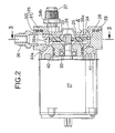
- the structure of the above Wesco-type pump is described below by referring to Figs. 2 to 4.
- the Wesco-type pump is provided with a light-metal housing 25 and a synthetic-resin rotor 26 rotatably housed in the housing 25, in which the rotor 26 is connected to a rotary shaft 28 of an electric motor 27 by a key 29.
- the housing 25 comprises a housing body 30 and a cover 31 interconnected by a plurality of bolts 32, 32, ...
- the electric motor 27 is connected to the housing body 30 at the opposite side as the cover 31 and a bearing 33 is set between the rotary shaft 28 and the housing body 30.
- the discoid rotor 26 is connected to the rotary shaft 28 through the key 29 by making both the sides approach and face the housing body 30 and cover 31 and both the sides of the outer periphery of the rotor 26 are provided with a large number of vane grooves 26a... and 26a... respectively at equal intervals in the circumferential direction. Moreover, a channel 34 with which the vane grooves 26a... and 26a... on the outer periphery of the rotor 26 are faced is formed between the housing body 30 and the cover 31.
- the channel 34 is formed like a circular arc with which approximately 80% of the outer periphery of the rotor 26 is faced from a suction port 34a at one end in the circumferential direction up to a discharge port 34b at the other end in the circumferential direction and a partition 35 for making the remaining approximately 20% of the outer periphery of the rotor 26 approach and face is provided for the housing 25 so as to demarcate the suction port 34a from the discharge port 34b.
- the channel 34 is formed as a pumping channel with the same channel area.
- the suction port 34a at one end of the channel 34 in the circumferential direction is formed so as to be an enlarged channel in which the channel area is made larger than that of the pumping channel in the range of a central angle ⁇ (e.g. 45°) about the axis line of the rotary shaft 28 and moreover, the channel 34 in the range of a central angle ⁇ (e.g. 30°) from the suction port 34a is formed so as not to suddenly change the channel area from the suction port 34a serving as an enlarged channel up to the pumping channel.
- a central angle ⁇ e.g. 45°
- the housing body 30 is connected to a suction-side connection pipe 36 connected to the suction port 34a so that the pipe 36 extends outward in a plane perpendicular to the axis line of the rotary shaft 28 and the cover 31 is connected to a discharge-side connection pipe 37 connected to the discharge port 34b so that the pipe 37 extends outward in parallel with the axis line of the rotary shaft 28.
- inside and outside double O rings 38 and 39 are provided between the housing body 30 and the cover 31 and also a pair of O rings 40 and 41 arranged in the axial direction are provided between the electric motor 27 and the housing body 30.
- the O rings 38 to 41 the O rings 38 and 40 at the side contacting the solution in the pump are made of a material having solution resistance such as EPDM rubber or silicone rubber and the O rings 39 and 41 at the outside air side are made of a material having a high air tightness such as NBR rubber.
- a gap 42 is formed between the outer periphery of the rotor 26 and the partition 35 and moreover, gaps 43 and 43 are formed between both the sides of the rotor 26, the housing body 30, and the cover 31.
- the rotor 26 is made of synthetic resin for reduction in weight and rotates in the solution containing water. Therefore, swelling of the rotor 26 due to water poses a problem.
- the rotor 26 is thin and discoid and the diameter D of the rotor 26 is much larger than the thickness of the rotor 26.
- the gap 42 between the outer periphery of the rotor 26 and the partition 35 has a larger dimensional change than the gaps 43 and 43 between both the sides of the rotor 26 and the housing 25.
- the swelling value of the rotor 26 in the radial direction poses a significant problem.
- machining allowance, thermal expansion, and swelling of the rotor 26, and fitting between the rotor 26 and the rotary shaft 28 are considered as the factors related to setting of the dimension ⁇ of the gap 42.
- it is possible to set the dimension ⁇ by considering the machining allowance, thermal expansion, and swelling of the rotor 26 and the machining allowance, thermal expansion value, and swelling value are basically proportional to the outer periphery diameter D of the rotor 26. Therefore, as the result of performing an experiment on the change of the pump efficiency to the change rate (2 ⁇ /D) ⁇ 100(%) of the dimension ⁇ of the gap 42 to the outer periphery diameter D of the rotor 26, a curve shown in Fig. 5 is obtained.
- the outer periphery diameter D of the rotor 26 is set in a range of 30 to 120 mm as a standard value for manufacture and strength. That is, when the outer periphery diameter D exceeds 120 mm, the rotor 26 must be thick in order to improve the strength and moreover, the number of steps, such as pre-cutting, increases for manufacturing the rotor 26 and a problem occurs with the dimensional accuracy. When the outer periphery diameter D is less than 30 mm, the difficulty in machining and accuracy increases.
- the upper limit of the dimensional change rate becomes 0.72% as shown in Fig. 5.
- the minimum dimensional change rate for securing the dimension ⁇ required to prevent the rotor 26 from locking by contacting with the partition 35 of the housing 25 is 0.18% as shown in Fig.
- the synthetic resin for forming the rotor 26 must have a small swelling rate to moisture. As such a synthetic resin for forming the rotor 26, resol-type phenol resin is preferable.
- resol-type phenol resin A is the resol-type high-heat phenol resin with the above trade name PM9625 and resol-type phenol resin B is the resol-type heat-resistant and impact phenol resin with the above trade name PM9630.
- the moisture content rate most suitable to control the corrosive action to the light metal while holding desired actions and sufficient cooling performance of a refrigerant and absorbent of the absorption-type cooling unit of the stationary-type household air conditioner is approximately 5 wt%.
- the above fluorine-containing alcohol and heterocyclic organic compound have a strong corrosiveness to a light metal.
- the components of the absorption-type cooling unit such as the evaporator 5, the absorber 6, the first generator 7, the second generator 8, the first rectifier 9, the second rectifier 10, the condenser 11, the first and second heat exchangers 12 and 13, the pumps P1, P2, and P3, and the pipes interconnecting these units 5 to 13 and P1 to P3 are made of a light metal in order to decrease the weight of the cooling unit.
- the rotor 26 is made of resol-type phenol resin in the Wesco-type pumps P1 to P3.
- the resol-type phenol resin is an ammonia-free phenol resin on a base of glass fibers, which has a small dimensional change and a small strength change caused by the solution and is superior in solution resistant stability. Therefore, it is possible to obtain a superior durability while decreasing the weights of the rotor 26 and housing 25, that is, the pumps P1 to P3 in weight.
- the above resol-type phenol resin is able to keep the degree of swelling due to moisture contained in the medium in a relatively large quantity at a very low level in order to improve the corrosion resistance of a light metal as shown in Fig. 6. Therefore, it is possible to obtain a desired pump performance by minimizing the dimensional change rate of the rotor 26 which greatly changes the gap between the housing 25 and the rotor 26 due to swelling.
- the dimension ⁇ of the gap 42 formed between the outer periphery of the rotor 26 and the partition 35 is set by considering the machining allowance, thermal expansion, and swelling of the rotor 26.
- an allowable value of the dimensional change rate due to swelling is 0.15% as described in relation with Fig. 5 and the maximum value of the moisture content rate of the medium to meet the allowable value 0.15% is set to 10 wt% as described in relation with Fig. 6.
Landscapes
- Engineering & Computer Science (AREA)
- Mechanical Engineering (AREA)
- General Engineering & Computer Science (AREA)
- Structures Of Non-Positive Displacement Pumps (AREA)
- Compositions Of Macromolecular Compounds (AREA)
Description
- The present invention relates to a medium circulation apparatus according to the preamble of claim 1.
- In the case of the above pump, the rotor is made of synthetic resin to decrease its weight, for example. However, if moisture is contained in a medium, the rotor made of synthetic resin is swelled by the moisture contained in the medium, the gap dimension between the housing and the rotor changes whereby the desired pump performance may not be obtained. Therefore, it is necessary to control the swelling of the rotor. Thus, Japanese Patent application Laid-Open No. 3-115794 discloses a material for suppressing the swelling of a rotor made of synthetic resin. In order to suppress the swelling due to the moisture contained in fuel, the rotor is made of a material obtained by blending phenol aralkyl resin and a filler with phenol resin.
- However, the above conventional rotor is used for a pump for force-feeding a fuel having a moisture content rate of up to approx. 0.5 wt%. In the case of a medium containing a solution that causes corroding of a light metal, Japanese Patent Publication No. 63-12504 discloses that corrosion resistance can be provided for the light metal by adding water to the solution until the moisture content rate of the medium is up to about 15 wt%. However, when applying the pump disclosed in Japanese Patent application Laid-Open No. 3-115794 to the medium having a large moisture content rate as mentioned above, there is insufficient swelling resistance and the desired pump performance cannot be obtained.
- Therefore, it is desired that a sufficient pump performance be obtained even when force-feeding a medium having a relatively large moisture content rate by a pump using a rotor made of synthetic resin. In the case of this pump, however, the gap dimension between the rotor and the housing greatly influences the pump performance. Therefore, in order to obtain a sufficient pump performance, it is necessary to secure a minimum gap dimension. Then, based on the minimum gap dimension, it is possible to set the upper limit value of the dimensional change rate of a rotor due to the swelling. On the other hand, in order to improve the corrosion resistance of a light metal, it is indispensable to set the degree of freedom of the moisture content rate of the medium, that is, the increased range of water quantity to be added, at a relatively large value and it is necessary to select synthetic resin for forming a rotor so that the degree of freedom of the moisture content rate in the medium can be relatively large with respect to the upper-limit dimensional change rate of the rotor due to the above-described swelling.
- US-A-2 782 722 discloses a coolant pump for an internal combustion engine. The coolant pump comprises a plastic impeller body made of a conventional phenol formaldehyde type of thermosetting plastic.
- US-A-3 846 045 discloses a centrifugal pump incorporated into the cooling system of an internal combustion engine comprising an impeller consisting of a mixture of thermosetting resin having a low coefficient of water absorption when heated and of a water-repellent filler not liable to undergo appreciable changes in its dimensions in the presence of water.
- FR-A-1 248 048 discloses a blade wheel for turbines, pumps or the like, in which the wheel is made of a molded synthetic material such as Rilsan, Bakelite or any other similar material.
- GB 929 790 discloses a centrifugal pump of a type adapted to be entirely submerged in the water or other liquid to be pumped. This document discloses the use of a synthetic resin material having the property of swelling to reduce bearing clearances.
- "Plastic in Pumps", Pumps - Pompes - Pumpen, Volume 130, 1977, XP002050745 discloses the use of plastic materials in pump construction.
- It is an object of the invention to provide a light-weight medium circulation apparatus comprising apump capable of obtaining a sufficient pump performance for circulating a solution having a characteristic of corroding light metal.
- This object is accomplished by a medium circulation apparatus according to claim 1.
- According to a first aspect of the present invention, in a pump comprising a fixed housing and a rotor made of synthetic resin and rotating in the housing which are adjacently arranged while forming a gap between the housing and the rotor to raise the pressure of a medium obtained by adding water to a solution, the rotor is formed with the synthetic resin so that the dimensional change rate of the rotor decreases to 0.15% or less relative to a medium having a moisture content rate of 10 wt% or less.
- The upper limit of the dimensional change rate of a rotor due to swelling by moisture can be set by considering a previously-expectable dimensional tolerance and thermal expansion in accordance with a minimum dimension necessary for the gap between a rotor and a housing in order to obtain a sufficient pump performance. When using synthetic resin for decreasing the dimensional change rate of the rotor to 0.15% or less, the upper limit value of the moisture content rate in a medium can be set at 10 wt%. Therefore, it is possible to sufficiently raise the moisture content rate in the medium while keeping a sufficient pump performance.
- Moreover, according to a second aspect of the present invention, the weight of a pump can be decreased while improving the corrosion resistance of a light metal by sufficiently increasing the moisture content rate in a medium because at least a portion of the pump except the rotor which contacts the medium is made of the light metal subject to being corroded by the solution.
- According to a third aspect of the present invention, a rotor is made of resol-type phenol resin. Moreover, according to a fourth aspect of the present invention, resol-type phenol resin is resol-type high-heat phenol resin equivalent to PM-HH-R in JIS-K-6915 or resol-type heat-resistant and impact phenol resin equivalent to PM-HM-R in JIS-K-6915.
- Resol-type phenol resin is ammonia-free phenol resin based on glass fiber, which has a small dimensional change and a small strength change in a solution and which is superior in solution-resistant stability. Therefore, it is possible to decrease the weight of a rotor, that is, a pump and moreover obtain a superior durability. Furthermore, resol-type phenol resin makes it possible to maintain the degree of swelling due to moisture at a very low level. Therefore, for a medium having a high moisture content rate in order to improve the corrosion resistance of a light metal, it is possible to greatly decrease the dimensional change rate of a rotor which greatly changes the gap dimension between a housing and the rotor due to swelling and thus, it is possible to obtain a desired pump performance.
- According to a fifth aspect of the present invention, the above pump is provided in a closed circuit for circulating a medium obtained by adding water to a solution having a function of corroding a light metal and at least a part of the portion constituting a part of the closed circuit and contacting the medium is made of a light metal. According to a sixth aspect of the present invention, a medium circulation apparatus comprises a low-pressure closed circuit. According to a seventh aspect of the present invention, a medium circulation apparatus comprises an absorption-type cooling unit or a pair of fluid-absorption-type circulation apparatuses.
- Even if at least a part of the closed circuit is made of a light metal, the corrosion resistance of the light metal is improved by using a pump capable of force-feeding a medium having a high moisture content rate with a sufficient pump performance.
- According to an eighth aspect of the present invention, a solution serving as a part of a medium used for an absorption-type cooling unit is made of fluorine-containing alcohol and heterocyclic organic compound.
- By using fluorine-containing alcohol serving as a refrigerant and heterocyclic organic compound serving as an absorbent, it is possible to obtain the performances required for a circulation medium of an absorption-type cooling unit such as low combustibility, high heat efficiency, noncrystallinity, superior heat stability, and high cooling capacity. Although fluorine-contained alcohol and heterocyclic organic compound have a strong corrosiveness to light metals, it is possible to weaken the corrosiveness by adding water to a solution.
- According to a ninth aspect of the present invention, the pump is a Wesco-type pump. This Wesco-type pump hardly causes cavitation and therefore, it is possible to minimize the occurrence of the cavitation in an absorption-type cooling unit serving as a low-pressure circuit. Even if the cavitation occurs, it is possible to provide impact resistance for a rotor by absorbing impact when bubbles collapse due to the cavitation by means of the elasticity of synthetic resin because the rotor is made of the synthetic resin.
- The above and other objects, features, and advantages of the present invention will become more apparent from the preferred embodiment described below in detail when taken in conjunction with the accompanying drawings.
- Figs. 1 to 6 show an embodiment of the present invention in which:
- Fig. 1 is a system diagram showing a structure of a stationary-type household air conditioner;
- Fig. 2 is a sectional view of the Wesco-type pump, taken along a line 2-2 in Fig. 3;
- Fig. 3 is a sectional view of the pump, taken along a line 3-3 in Fig. 2;
- Fig. 4 is an enlarged view of a portion within the ellipse 4 in Fig. 2;
- Fig. 5 is a graph showing a relation of pump efficiency and moisture content rate to dimensional change rate; and
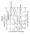
- Fig. 6 is a graph showing a relation of dimensional change rate due to swelling to moisture content rate.
-
- First, in Fig. 1, the absorption-type cooling unit provided for the stationary-type household air conditioner comprising an
evaporator 5, an absorber 6, two-stage first and second generators 7 and 8, a first rectifier orpartial condenser 9, a second rectifier orpartial condenser 10, acondenser 11, and first andsecond heat exchangers - The
evaporator 5 stores a refrigerant and the absorber 6 stores an absorbing solution containing an absorbent. Theevaporator 5 and the absorber 6 are connected to each other and kept under a low-pressure condition at an absolute pressure of approximately 3999,66 Pa (30 mmHG), in which the refrigerant is evaporated by theevaporator 5 and the refrigerant is absorbed by the absorbing solution in the absorber 6. - A
conduit 5a for circulating brine is set in theevaporator 5 and the refrigerant changes to a low-pressure refrigerant vapor by obtaining the heat of evaporation from the brine. Moreover, the refrigerant in theevaporator 5 is discharged from theevaporator 5 by a pump P1, with only a small part of the discharged refrigerant being supplied to thesecond rectifier 10, and the remaining major part of the refrigerant being sprayed onto theconduit 5a by a not-illustrated spraying means in theevaporator 5. - In the absorber 6, heat of absorption is produced because refrigerant vapor is absorbed by the absorbing solution. However, the absorbing solution is cooled due to heat exchange with the brine circulating through the
conduit 6a provided in the absorber 6, thereby accelerating absorption of the refrigerant vapor in the absorber 6 and refrigerant evaporation in theevaporator 5. Moreover, the absorbing solution in the absorber 6 is discharged from the absorber 6 by the pump P2 and sprayed on theconduit 6a by a not-illustrated spraying means in the absorber 6. - The absorbent concentration of the absorbing solution in the absorber 6 is lowered by absorbing the refrigerant vapor and the absorbing capacity is deteriorated. Therefore, in order to restore the absorbing capacity of the absorbing solution by separating the refrigerant vapor from the absorbing solution, a diluted solution discharged from the absorber 6 by a pump P3 is sent to the first generator 7.
- The first generator 7 constitutes a double-effect generator together with the second generator 8 and the first and
second rectifiers burner 14. The diluted solution sent from the absorber 6 is heated by theburner 14 and boiled in the first generator 7 and refrigerant vapor produced from the boiled diluted solution is led to thefirst rectifier 9. The refrigerant vapor is cooled by heat exchange with the brine flowing through aconduit 9a provided in thefirst rectifier 9, and the absorbent component remaining in the refrigerant vapor is separated from the refrigerant vapor and returned to the first generator 7. Thus, an intermediate solution whose concentration is raised stays at the bottom of the first generator 7 and the intermediate solution is led to the second generator 8. - The refrigerant vapor passed through the
first rectifier 9 still has a relatively high temperature and it is led to the second generator 8. In the second generator 8, the intermediate solution is heated by the refrigerant vapor supplied from thefirst rectifier 9 and the refrigerant vapor produced in the second generator 8 is introduced into thesecond rectifier 10. Thus, in thesecond rectifier 10, the refrigerant vapor is cooled through heat exchange with the brine flowing through aconduit 10a provided in thesecond rectifier 10, the absorbent component remaining in the refrigerant vapor is separated from the refrigerant vapor and returned to the second generator 8, a concentrated solution with a high concentration stays at the bottom of the second generator 8, and the concentrated solution is returned to the absorber 6 and used as an absorbing solution again. - The
first heat exchanger 12 performs heat exchange between the concentrated solution returned to the absorber 6 from the second generator 8 and the diluted solution led from the absorber 6 by the pump P3. The concentrated solution with a relatively high temperature sent from the second generator 8 is cooled by thefirst heat exchanger 12 and returned to the absorber 6 and the diluted solution with a relatively low temperature sent from the absorber 6 is preliminarily heated by thefirst heat exchanger 12. Moreover, thesecond heat exchanger 13 performs heat exchange between the diluted solution led from thefirst heat exchanger 12 to the first generator 7 and the intermediate solution sent from the first generator 7 to the second generator 8. The diluted solution is further heated by thesecond heat exchanger 13 and sent to the first generator 7 and the intermediate solution is cooled by thesecond heat exchanger 13 and sent to the second generator 8. - The refrigerant vapor passing through the
second rectifier 10 is introduced into thecondenser 11 and the refrigerant vapor whose pressure is reduced by apressure reducing valve 15 is introduced into thecondenser 11 from the second generator 8. Thus, the purity of the refrigerant vapor led to thecondenser 11 is increased up to, for example, approximately 99.8% and cooled by the cooling air of afan 16 associated with thecondenser 11, whereby, the refrigerant vapor is condensed in thecondenser 11 as a refrigerant solution and recovered by theevaporator 5 via apressure reducing valve 17. - Though the refrigerant recovered by the
evaporator 5 has a very high purity as described above, an absorbent which is very slightly mixed with the refrigerant accumulates in theevaporator 5 over a long period of operation and therefore the purity of the refrigerant in theevaporator 5 slowly lowers. Therefore, a very small part of the refrigerant discharged from theevaporator 5 by the pump P1 is sent to thesecond rectifier 10 and treated together with the refrigerant vapor produced from the intermediate solution in thesecond rectifier 10 so as to raise the purity of the refrigerant. - A suction port of the pump P4 is connected to the
conduit 5a of theevaporator 5. Moreover, aconduit 6a of the absorber 6 is connected to one end of theconduit 10a of thesecond rectifier 10 and the other end of theconduit 10a is connected to one end of theconduit 9a of thefirst rectifier 9 through a three-way selector valve 18 and also connected to abypass conduit 9b bypassing theconduit 9a through the three-way selector valve 18. The three-way selector valve 18 can switch between the state of connecting theconduit 10a to theconduit 9a and the state of connecting theconduit 10a to thebypass conduit 9b and thus can control whether to circulate brine through theconduit 9a of thefirst rectifier 9. Theconduit 9a andbypass conduit 9b are connected to the suction port of the pump P5. - The brine circulating through the
conduit 5a of theevaporator 5 is cooled because the latent heat of evaporation due to evaporation of the refrigerant in theevaporator 5 is removed and the brine circulating through theconduit 6a of the absorber 6,conduit 10a of thesecond rectifier 10, and theconduit 9a of thefirst rectifier 9 is heated due to heat exchange with the absorbing solution and refrigerant vapor. Thus, the brine cooled and the brine heated as described above are alternatively switched by four-way selector valves conduit 19a provided in anindoor unit 19 and aconduit 20a provided in a radiator orsensible heat exchanger 20. That is, it is possible to set the environment so that the cooled brine is supplied to theconduit 19a of theindoor unit 19 during cooling and the air cooled by theconduit 19a can be supplied into a room by a not-illustrated fan and the heated brine is supplied to theconduit 19a of theindoor unit 19 during heating. - In the case of the absorption-type cooling or heating unit of the above stationary-type household air conditioner, at least some of the component units such as the
evaporator 5, absorber 6, first generator 7, second generator 8,first rectifier 9,second rectifier 10,condenser 11, first andsecond heat exchangers units 5 to 13 and P1 to P3 each other are made of a light metal in order to decrease the weight of the air conditioner. - As the above-described light metal, aluminum, magnesium, aluminum alloy, magnesium alloy, or titanium alloy is effectively used so as to decrease the air conditioner in weight and size. Moreover, as the above aluminum alloy, various alloys are used such as an Al-Cu-Mg, Al-Mg, Al-Si-Mg-Ni, Al-Mg-Cr, Al-Si-Mg, or Al-Cu-Mg-Zn alloy.
- Furthermore, the medium circulating through the above absorption-type cooling unit is obtained by adding water to a solution made of fluorine-containing alcohol serving as a refrigerant and a heterocyclic organic compound serving as an absorbent.
- As the fluorine-containing alcohol, it is preferable to use fluorine-containing alcohol having a boiling point between 40 to 120°C. Moreover, from the viewpoint of the cooling capacity of the absorption-type cooling unit, it is preferable to use alcohol having a perfluoroalkyl group such as a trifluoromethyl group and it is particularly preferable to use fluorine-containing ethanol or fluorine-containing propanol such as 2,2,2-trifluoro-1-ethanol (boiling point of 73.6°C) or 2,2,3,3,3-pentafluoro-1-propanol (boiling point of 80.7°C)
- It is preferable that the heterocyclic organic compound serving as an absorbent is a derivative of imidazolidine, thiazole, or pylimidine. As a imidazolidine derivative, it is preferable to use a substance having the following chemical formula.

- In the above chemical formula, R1, R2, and R3 denote independently a hydrogen atom or an alkyl group having 1-4 carbon atoms and R4 denotes an alkyl group having 1 to 4 carbon atoms.
- Above all, it is preferable to use 1,3-dimethyl-2-imidazolidine, 1,3-diethyl-2-imidazolidone, 1,3-dipropyl-2-imidazolidone, or 1,3-dipropyl-4-methyl-2-imidazolidone. It is particularly preferable to use 1,3-dimethyl-2-imidazolidone or 1,3-dipropyl-2-imidazolidone because they are superior in heat exchange performance as an absorbent.
- By using the above solution made of fluorine-containing alcohol and heterocyclic organic compound, it is possible to obtain the performances required for the circulation medium of the absorption-type cooling unit such as low combustibility, high heat efficiency, noncrystallinity, superior heat stability, and high cooling capacity. However, fluorine-containing alcohol and heterocyclic organic compound have a strong corrosiveness to light metals but it is possible to weaken the corrosiveness to the light metals by adding water to the solution.
- As the pumps P1, P2, and P3 used for the absorption-type cooling unit which is a low-pressure closed circuit system, it is the most suitable to use a Wesco-type pump capable of minimizing cavitation easily produced due to the low pressure in a low-pressure circuit. Also, it is possible to use a gear pump or trochoid pump. Furthermore, a centrifugal pump, roller vane pump, and the like are used as the pumps P4 and P5 for feeding brine.
- The structure of the above Wesco-type pump is described below by referring to Figs. 2 to 4. The Wesco-type pump is provided with a light-
metal housing 25 and a synthetic-resin rotor 26 rotatably housed in thehousing 25, in which therotor 26 is connected to arotary shaft 28 of anelectric motor 27 by a key 29. - The
housing 25 comprises ahousing body 30 and acover 31 interconnected by a plurality ofbolts electric motor 27 is connected to thehousing body 30 at the opposite side as thecover 31 and abearing 33 is set between therotary shaft 28 and thehousing body 30. - The
discoid rotor 26 is connected to therotary shaft 28 through the key 29 by making both the sides approach and face thehousing body 30 andcover 31 and both the sides of the outer periphery of therotor 26 are provided with a large number ofvane grooves 26a... and 26a... respectively at equal intervals in the circumferential direction. Moreover, achannel 34 with which thevane grooves 26a... and 26a... on the outer periphery of therotor 26 are faced is formed between thehousing body 30 and thecover 31. Thechannel 34 is formed like a circular arc with which approximately 80% of the outer periphery of therotor 26 is faced from asuction port 34a at one end in the circumferential direction up to adischarge port 34b at the other end in the circumferential direction and a partition 35 for making the remaining approximately 20% of the outer periphery of therotor 26 approach and face is provided for thehousing 25 so as to demarcate thesuction port 34a from thedischarge port 34b. - Moreover, most of the
channel 34 is formed as a pumping channel with the same channel area. Thesuction port 34a at one end of thechannel 34 in the circumferential direction is formed so as to be an enlarged channel in which the channel area is made larger than that of the pumping channel in the range of a central angle α (e.g. 45°) about the axis line of therotary shaft 28 and moreover, thechannel 34 in the range of a central angle β (e.g. 30°) from thesuction port 34a is formed so as not to suddenly change the channel area from thesuction port 34a serving as an enlarged channel up to the pumping channel. Thus, thehousing body 30 is connected to a suction-side connection pipe 36 connected to thesuction port 34a so that thepipe 36 extends outward in a plane perpendicular to the axis line of therotary shaft 28 and thecover 31 is connected to a discharge-side connection pipe 37 connected to thedischarge port 34b so that thepipe 37 extends outward in parallel with the axis line of therotary shaft 28. - Moreover, in order to keep the air tightness between the inside and outside of the pump, inside and outside double O rings 38 and 39 are provided between the
housing body 30 and thecover 31 and also a pair of O rings 40 and 41 arranged in the axial direction are provided between theelectric motor 27 and thehousing body 30. Furthermore, among the O rings 38 to 41, the O rings 38 and 40 at the side contacting the solution in the pump are made of a material having solution resistance such as EPDM rubber or silicone rubber and the O rings 39 and 41 at the outside air side are made of a material having a high air tightness such as NBR rubber. - In the case of the above Wesco-type pump, a
gap 42 is formed between the outer periphery of therotor 26 and the partition 35 and moreover,gaps rotor 26, thehousing body 30, and thecover 31. Thus, the dimensions of thesegaps rotor 26 is made of synthetic resin for reduction in weight and rotates in the solution containing water. Therefore, swelling of therotor 26 due to water poses a problem. However, therotor 26 is thin and discoid and the diameter D of therotor 26 is much larger than the thickness of therotor 26. Therefore, for a dimensional change value of therotor 26 due to swelling, thegap 42 between the outer periphery of therotor 26 and the partition 35 has a larger dimensional change than thegaps rotor 26 and thehousing 25. Thus, the swelling value of therotor 26 in the radial direction poses a significant problem. - When the initial setting of the dimension δ (see Fig. 3) of the
gap 42 is a very small amount, no problem occurs with the pump performance. However, the swelling of therotor 26 in the radial direction makes therotor 26 closely approach or contact the partition 35 of thehousing 25 and thereby, rubbing or locking may occur. Moreover, when the initial setting of the dimension δ is increased, a desired pump performance cannot be obtained at the initial operating stage. - In this case, machining allowance, thermal expansion, and swelling of the
rotor 26, and fitting between therotor 26 and therotary shaft 28 are considered as the factors related to setting of the dimension δ of thegap 42. Practically, however, it is possible to set the dimension δ by considering the machining allowance, thermal expansion, and swelling of therotor 26 and the machining allowance, thermal expansion value, and swelling value are basically proportional to the outer periphery diameter D of therotor 26. Therefore, as the result of performing an experiment on the change of the pump efficiency to the change rate (2×δ/D)×100(%) of the dimension δ of thegap 42 to the outer periphery diameter D of therotor 26, a curve shown in Fig. 5 is obtained. - In this case, the outer periphery diameter D of the
rotor 26 is set in a range of 30 to 120 mm as a standard value for manufacture and strength. That is, when the outer periphery diameter D exceeds 120 mm, therotor 26 must be thick in order to improve the strength and moreover, the number of steps, such as pre-cutting, increases for manufacturing therotor 26 and a problem occurs with the dimensional accuracy. When the outer periphery diameter D is less than 30 mm, the difficulty in machining and accuracy increases. - When setting the lower limit of the pump efficiency at 20% in accordance with the above setting range of the outer periphery diameter D of the
rotor 26 and the operation of therotor 26 under a low pressure (absolute pressure of 2666,44 Pa to 5332,88 Pa (20 to 40 mmHG)), the upper limit of the dimensional
change rate becomes 0.72% as shown in Fig. 5. Moreover, the minimum dimensional change rate for securing the dimension δ required to prevent therotor 26 from locking by contacting with the partition 35 of thehousing 25 is 0.18% as shown in Fig. 5 and a value obtained by subtracting the minimum dimensional change rate 0.18% from the upper limit value 0.72% of the above dimensional change rate becomes an allowable dimensional change rate 0.54% due to machining allowance, thermal expansion, and swelling. In this case, the upper limit value of the dimensional change rate due to machining allowance and thermal expansion is 0.39% and therefore, the allowable change rate due to swelling becomes 0.15% at maximum. - As described above, in order to prevent the
rotor 26 made of synthetic resin from locking by contacting with the partition 35 of thehousing 25, it is necessary to control the maximum value of the dimensional change rate due to swelling of therotor 26 to 0.15%. However, the rate of moisture contained in the medium is required to-be a relatively large value in order to suppress the corrosive action on a light metal. Therefore, the synthetic resin for forming therotor 26 must have a small swelling rate to moisture. As such a synthetic resin for forming therotor 26, resol-type phenol resin is preferable. - Performing an experiment on the dimensional change rate due to swelling to moisture content rate by using resol-type high-heat phenol resin with the trade name PM9625 (made by Sumitomo Bakelite Co., Ltd.; equivalent to PM-HH-R in JIS-K-6915) and resol-type heat-resistant and impact phenol resin with the trade name PM9630 (made by Sumitomo Bakelite Co., Ltd.; equivalent to PM-HM-R in JIS-K-6915), the results shown in Fig. 6 are obtained. In Fig. 6, resol-type phenol resin A is the resol-type high-heat phenol resin with the above trade name PM9625 and resol-type phenol resin B is the resol-type heat-resistant and impact phenol resin with the above trade name PM9630.
- As apparent from Fig. 6, in order to control the dimensional change rate to 0.15% or less, it is possible to set a moisture content rate by increasing it up to 17 wt% for the resol-type phenol resin A and up to 12 wt% for the resol-type phenol resin B. The results show that the dimensional change rate due to swelling of the
rotor 26 made of resol-type phenol resin can be controlled to 0.15% or less when setting a moisture content rate at 10 wt% or less by also considering an allowance. - It is apparent from the experiment results by the present inventors that the moisture content rate most suitable to control the corrosive action to the light metal while holding desired actions and sufficient cooling performance of a refrigerant and absorbent of the absorption-type cooling unit of the stationary-type household air conditioner is approximately 5 wt%. Moreover, as described above, it is possible to provide a degree of freedom of setting the range of the moisture content rate for further improving the corrosion resistance because the moisture content rate of the synthetic-
resin rotor 26 having a dimensional change rate due to swelling of 0.15% or less can be increased up to 10 wt%. - On the other hand, by performing an experiment on the dimensional change rate due to swelling based on the moisture content rate of phenol resin mixed with phenol aralkyl resin and filler (disclosed in the Japanese Patent application Laid-Open No. 3-115794) for comparison, the curves shown as comparative examples A and B in Fig. 6 are obtained. From Fig. 6, it is clear that for the comparative example A water can be added only up to a moisture content rate of approximately 2 wt% in order to meet the allowable dimensional change rate due to swelling and a moisture content rate required to suppress the corrosion of a light metal cannot be relatively large. The comparative example B cannot meet the maximum dimensional change rate due to swelling of 0.15% with any added water, as shown in Fig. 6.
- Next, functions of the embodiment will be described. By using a solution serving as a part of a medium and made of fluorine-containing alcohol serving as a refrigerant and heterocyclic organic compound serving as an absorbent for an absorption-type cooling unit which is a low-pressure closed circuit, it is possible to provide the performances such as low combustibility, high heat efficiency, noncrystallinity, superior heat stability, and high freezing capacity which are requested for the absorption-type cooling unit.
- The above fluorine-containing alcohol and heterocyclic organic compound have a strong corrosiveness to a light metal. However, at least some of the components of the absorption-type cooling unit such as the
evaporator 5, the absorber 6, the first generator 7, the second generator 8, thefirst rectifier 9, thesecond rectifier 10, thecondenser 11, the first andsecond heat exchangers units 5 to 13 and P1 to P3 are made of a light metal in order to decrease the weight of the cooling unit. It is possible to weaken the corrosiveness by adding water to the solution made of fluorine-containing alcohol and heterocyclic organic compound and to suppress the corrosion even if at least a part of the pump contacting the medium is made of a light metal in order to decrease the weight as described above. - Moreover, by using a Wesco-type pump for the pumps P1, P2, and P3 used for the absorption-type cooling unit constituting a low-pressure closed circuit, it is possible to minimize cavitation which is easily caused in the pumps P1 to P3 because of the low pressure and moreover, the
rotor 26 is made of resol-type phenol resin in the Wesco-type pumps P1 to P3. The resol-type phenol resin is an ammonia-free phenol resin on a base of glass fibers, which has a small dimensional change and a small strength change caused by the solution and is superior in solution resistant stability. Therefore, it is possible to obtain a superior durability while decreasing the weights of therotor 26 andhousing 25, that is, the pumps P1 to P3 in weight. Moreover, even if cavitation occurs, it is possible to provide impact resistance for therotor 26 by absorbing the impact when bubbles collapse due to cavitation by the flexibility of the synthetic resin because therotor 26 is made of the synthetic resin. - The above resol-type phenol resin is able to keep the degree of swelling due to moisture contained in the medium in a relatively large quantity at a very low level in order to improve the corrosion resistance of a light metal as shown in Fig. 6. Therefore, it is possible to obtain a desired pump performance by minimizing the dimensional change rate of the
rotor 26 which greatly changes the gap between thehousing 25 and therotor 26 due to swelling. - In the case of a Wesco-type pump, the dimension δ of the
gap 42 formed between the outer periphery of therotor 26 and the partition 35 is set by considering the machining allowance, thermal expansion, and swelling of therotor 26. In this case, an allowable value of the dimensional change rate due to swelling is 0.15% as described in relation with Fig. 5 and the maximum value of the moisture content rate of the medium to meet the allowable value 0.15% is set to 10 wt% as described in relation with Fig. 6. Therefore, it is possible to add enough water to suppress the corrosion of a light metal due to the medium to the solution and moreover, keep the dimension of the gap between therotor 26 and thehousing 25 that changes due to swelling of therotor 26 within an allowable value, and obtain a desired pump performance.
Claims (8)
- A medium circulation apparatus comprising a pump (P1, P2, P3) in a closed circuit which circulates a medium consisting of water and a solution having a characteristic of corroding light metal wherein at least a portion of components constituting the closed circuit and contacting the medium is made of a light metal, said pump (P1, P2, P3) having a fixed housing (25) and having a rotor (26) made of synthetic resin and rotating in the housing (25), said housing (25) and said rotor (26) being positioned to form a gap (42) between an inner surface of the housing (30) and an outer periphery of the rotor (26) to raise the pressure of the medium, characterized in that said medium contains a water moisture content rate of more than 2 wt% and less than 17 wt% and the rotor (26) is made of a resol-type phenol resin such that its dimensional change rate due to swelling is of 0.15% or less when being exposed to said medium.
- The medium circulation apparatus according to claim 1, wherein at least a portion (30, 31) of said pump (25) contacting the medium other than the rotor (26) is made of a light metal subject to being corroded by the solution.
- The medium circulation apparatus according to any one of claims 1 or 2, wherein the moisture content rate of the medium is less than 12 wt%.
- The medium circulation apparatus according to any one of claims 1 to 3, wherein the moisture content rate of the medium is between about 5 wt% and 10 wt%.
- The medium circulation apparatus according to any one of claims 1 to 4, wherein the apparatus comprises a low-pressure closed circuit.
- The medium circulation apparatus according to any one of claims 1 to 5, wherein the apparatus is an absorption-type cooling unit.
- The medium circulation apparatus according to any one of claims 1 to 6, wherein a solution which is a part of the medium is made of fluorine-containing alcohol and heterocyclic organic compound.
- The medium circulation apparatus according to any one of claims 1 to 7, wherein the pump (P1, P2, P3) is a Wesco-type pump.
Applications Claiming Priority (3)
| Application Number | Priority Date | Filing Date | Title |
|---|---|---|---|
| JP23649896 | 1996-09-06 | ||
| JP8236498A JPH1082395A (en) | 1996-09-06 | 1996-09-06 | Pump and medium circulation device |
| JP236498/96 | 1996-09-06 |
Publications (2)
| Publication Number | Publication Date |
|---|---|
| EP0828081A1 EP0828081A1 (en) | 1998-03-11 |
| EP0828081B1 true EP0828081B1 (en) | 2003-04-16 |
Family
ID=17001629
Family Applications (1)
| Application Number | Title | Priority Date | Filing Date |
|---|---|---|---|
| EP97115373A Expired - Lifetime EP0828081B1 (en) | 1996-09-06 | 1997-09-04 | Pump and medium circulation apparatus |
Country Status (6)
| Country | Link |
|---|---|
| US (1) | US6126386A (en) |
| EP (1) | EP0828081B1 (en) |
| JP (1) | JPH1082395A (en) |
| KR (1) | KR100270219B1 (en) |
| CN (1) | CN1137333C (en) |
| DE (1) | DE69720891T2 (en) |
Families Citing this family (6)
| Publication number | Priority date | Publication date | Assignee | Title |
|---|---|---|---|---|
| JP2002168188A (en) * | 2000-09-20 | 2002-06-14 | Mitsuba Corp | Regenerative pump |
| US6854960B2 (en) | 2002-06-24 | 2005-02-15 | Electric Boat Corporation | Segmented composite impeller/propeller arrangement and manufacturing method |
| JP2005113686A (en) * | 2003-10-02 | 2005-04-28 | Aisan Ind Co Ltd | Fuel pump |
| JP5454423B2 (en) * | 2010-03-29 | 2014-03-26 | 株式会社豊田自動織機 | Electric compressor |
| US20200032790A1 (en) * | 2018-07-25 | 2020-01-30 | Ampco Pumps Company | Positive Displacement Pump With Shaft-Mounted Sleeve |
| JP7067505B2 (en) * | 2019-02-15 | 2022-05-16 | トヨタ自動車株式会社 | Fuel pump diagnostic device |
Family Cites Families (16)
| Publication number | Priority date | Publication date | Assignee | Title |
|---|---|---|---|---|
| DE266481C (en) * | ||||
| US2782722A (en) * | 1955-08-01 | 1957-02-26 | Ford Motor Co | Plastic impeller |
| FR1248048A (en) * | 1959-10-28 | 1960-12-09 | Paulde Ets | Impeller or blades for pumps or similar machines and machines fitted therewith |
| GB929790A (en) * | 1960-07-05 | 1963-06-26 | Tait Mfg Co | Improvements in or relating to centrifugal pumps |
| US3354529A (en) * | 1963-07-29 | 1967-11-28 | Ford Motor Co | Impeller making |
| FR2181111A5 (en) * | 1972-04-17 | 1973-11-30 | Mecanique Ind Int | |
| JPS592477B2 (en) * | 1980-02-12 | 1984-01-18 | 三洋電機株式会社 | Absorption liquid for absorption refrigerators |
| JP2643477B2 (en) * | 1989-09-27 | 1997-08-20 | 新神戸電機株式会社 | Pump rotor |
| DE4029435A1 (en) * | 1990-09-17 | 1992-03-19 | Freudenberg Carl Fa | BEARING PIN FOR THE BLADE WHEEL OF A COOLANT PUMP |
| JP3307019B2 (en) * | 1992-12-08 | 2002-07-24 | 株式会社デンソー | Regenerative pump |
| JPH06312504A (en) * | 1993-04-28 | 1994-11-08 | Canon Inc | INKJET HEAD AND INKJET DEVICE HAVING THE HEAD |
| JPH07157631A (en) * | 1993-12-03 | 1995-06-20 | Maruzen Petrochem Co Ltd | Thermosetting resin composition |
| JP3463356B2 (en) * | 1994-06-30 | 2003-11-05 | 株式会社デンソー | Wesco pump |
| US5549446A (en) * | 1995-08-30 | 1996-08-27 | Ford Motor Company | In-tank fuel pump for highly viscous fuels |
| US5765992A (en) * | 1996-01-11 | 1998-06-16 | Denso Corporation | Regenerative pump |
| JP3514907B2 (en) * | 1996-04-05 | 2004-04-05 | 本田技研工業株式会社 | Absorption refrigerator |
-
1996
- 1996-09-06 JP JP8236498A patent/JPH1082395A/en active Pending
-
1997
- 1997-09-03 KR KR1019970045648A patent/KR100270219B1/en not_active Expired - Fee Related
- 1997-09-04 EP EP97115373A patent/EP0828081B1/en not_active Expired - Lifetime
- 1997-09-04 US US08/923,235 patent/US6126386A/en not_active Expired - Fee Related
- 1997-09-04 DE DE69720891T patent/DE69720891T2/en not_active Expired - Fee Related
- 1997-09-05 CN CNB971184038A patent/CN1137333C/en not_active Expired - Fee Related
Also Published As
| Publication number | Publication date |
|---|---|
| JPH1082395A (en) | 1998-03-31 |
| KR100270219B1 (en) | 2000-11-01 |
| KR19980024310A (en) | 1998-07-06 |
| DE69720891T2 (en) | 2004-02-26 |
| CN1137333C (en) | 2004-02-04 |
| US6126386A (en) | 2000-10-03 |
| CN1186178A (en) | 1998-07-01 |
| DE69720891D1 (en) | 2003-05-22 |
| EP0828081A1 (en) | 1998-03-11 |
Similar Documents
| Publication | Publication Date | Title |
|---|---|---|
| CN1232747C (en) | Self-contained regulating valve, and compression type refrigerating machine having the same | |
| US6126386A (en) | Pump and medium circulation apparatus | |
| JPS5887182A (en) | Composition for compression type heat pumping fluid and house heating or air conditioning method thereby | |
| KR20240017369A (en) | Low pressure chamber rotary compressors and air conditioners | |
| US20060055173A1 (en) | Cooled electrical generator | |
| US6250102B1 (en) | Oil and refrigerant pump for centrifugal chiller | |
| US20080085206A1 (en) | Fluid Machine | |
| JP2014148910A (en) | Power generator | |
| CN212343579U (en) | Stator assembly and rotary compressor | |
| CN219299526U (en) | Pump body assembly, compressor and refrigeration equipment | |
| US4805419A (en) | Absorption type heat exchanging apparatus | |
| EP3899272B1 (en) | Aluminum compressor with sacrificial cladding | |
| CN215213941U (en) | Compressor internal heat radiation structure | |
| CN1237313C (en) | Enclosed rotary compressor | |
| CN219163665U (en) | Degassing and fluid supplementing structure for energy storage thermal management and energy storage thermal management system | |
| JP2018068021A (en) | Turbomachine and refrigeration cycle apparatus using the same | |
| JPH11257817A (en) | Cooling system | |
| Haselden | Potential of the single-screw compressor | |
| US3608328A (en) | Absorption refrigeration system | |
| CN1417479A (en) | Special rotary-vane vacuum pump | |
| CN223553170U (en) | Motor, compressor and air conditioner | |
| CN216447176U (en) | High-efficient automobile engine cooling water pump | |
| JP2974877B2 (en) | Solution pump for absorption chiller / heater | |
| JP2024145400A (en) | Compressor | |
| Ali et al. | with Vapor Injection (EVI) and Inverter Technology for High-Efficiency HVAC |
Legal Events
| Date | Code | Title | Description |
|---|---|---|---|
| PUAI | Public reference made under article 153(3) epc to a published international application that has entered the european phase |
Free format text: ORIGINAL CODE: 0009012 |
|
| AK | Designated contracting states |
Kind code of ref document: A1 Designated state(s): DE FR GB |
|
| AX | Request for extension of the european patent |
Free format text: AL;LT;LV;RO;SI |
|
| 17P | Request for examination filed |
Effective date: 19980416 |
|
| AKX | Designation fees paid |
Free format text: DE FR GB |
|
| RBV | Designated contracting states (corrected) |
Designated state(s): DE FR GB |
|
| 17Q | First examination report despatched |
Effective date: 20020124 |
|
| GRAH | Despatch of communication of intention to grant a patent |
Free format text: ORIGINAL CODE: EPIDOS IGRA |
|
| GRAH | Despatch of communication of intention to grant a patent |
Free format text: ORIGINAL CODE: EPIDOS IGRA |
|
| GRAA | (expected) grant |
Free format text: ORIGINAL CODE: 0009210 |
|
| AK | Designated contracting states |
Designated state(s): DE FR GB |
|
| REG | Reference to a national code |
Ref country code: GB Ref legal event code: FG4D |
|
| REF | Corresponds to: |
Ref document number: 69720891 Country of ref document: DE Date of ref document: 20030522 Kind code of ref document: P |
|
| PGFP | Annual fee paid to national office [announced via postgrant information from national office to epo] |
Ref country code: DE Payment date: 20030731 Year of fee payment: 7 |
|
| PGFP | Annual fee paid to national office [announced via postgrant information from national office to epo] |
Ref country code: GB Payment date: 20030828 Year of fee payment: 7 |
|
| PGFP | Annual fee paid to national office [announced via postgrant information from national office to epo] |
Ref country code: FR Payment date: 20030925 Year of fee payment: 7 |
|
| ET | Fr: translation filed | ||
| PLBE | No opposition filed within time limit |
Free format text: ORIGINAL CODE: 0009261 |
|
| STAA | Information on the status of an ep patent application or granted ep patent |
Free format text: STATUS: NO OPPOSITION FILED WITHIN TIME LIMIT |
|
| 26N | No opposition filed |
Effective date: 20040119 |
|
| PG25 | Lapsed in a contracting state [announced via postgrant information from national office to epo] |
Ref country code: GB Free format text: LAPSE BECAUSE OF NON-PAYMENT OF DUE FEES Effective date: 20040904 |
|
| PG25 | Lapsed in a contracting state [announced via postgrant information from national office to epo] |
Ref country code: DE Free format text: LAPSE BECAUSE OF NON-PAYMENT OF DUE FEES Effective date: 20050401 |
|
| GBPC | Gb: european patent ceased through non-payment of renewal fee |
Effective date: 20040904 |
|
| PG25 | Lapsed in a contracting state [announced via postgrant information from national office to epo] |
Ref country code: FR Free format text: LAPSE BECAUSE OF NON-PAYMENT OF DUE FEES Effective date: 20050531 |
|
| REG | Reference to a national code |
Ref country code: FR Ref legal event code: ST |