BACKGROUND OF THE INVENTION
1. Field of the Invention
The present invention relates to a device for
detecting knocking in an internal combustion engine by
using ionic current. More particularly, the invention
relates to a device for detecting knocking of an internal
combustion engine which, even when spike noise or noise
due to disturbance of the flame in low-load running are
generated, does not erroneously detect it as knocking.
2. Prior Art
In an internal combustion engine using gasoline
as a fuel, a gas mixture compressed by a piston is
ignited by a spark plug and is burned to produce an
output. That is, in normal combustion, a flame nucleus
in a gas mixture is formed near the gap of the spark
plug, and propagates over the whole combustion chamber.
The ignition timing of the spark plug has an
intimate relationship with the output of the internal
combustion engine. When the ignition timing is too late,
the propagation speed of the flame becomes slow.
Therefore, the combustion becomes slow, resulting in a
decrease in the combustion efficiency and, hence, in a
decrease in the output of the internal combustion engine.
When the ignition timing is too early, on the
other hand, the propagation of flame is fast, whereby the
maximum pressure of combustion rises and the output of
the internal combustion engine increases. When the
ignition timing is too early, however, there takes place
knocking in which the mixture gas is self-ignited prior
to the propagation of the flame, often damaging the
internal combustion engine.
That is, it is advantageous to operate the
internal combustion engine in a region where the ignition
timing is set just before the occurrence of knocking
(MBT: minimum spark advance for best torque) from the
standpoint of fuel efficiency and output. It is very
important to reliably detect the occurrence of knocking.
A knock sensor which is a vibration sensor has
heretofore been used for detecting knocking. However, a
device has also been studied which detects knocking by
utilizing the phenomenon that ions are generated in the
combustion chamber due to the combustion of the mixture
gas and an ionic current flows.
Fig. 1 is a diagram schematically illustrating
an ignition circuit for an internal combustion engine,
wherein an end of a primary coil 111 of an ignition coil
11 is connected to the positive electrode of a battery
12. The other end is grounded via the collector and the
emitter of a switching transistor 13 included in an
igniter.
The base of the transistor 13 is connected to
an ignition timing control unit 14, so that the
transistor 13 is turned on when an ignition signal IGT is
output from the ignition timing control unit 14.
An end of a secondary coil 112 of the ignition
coil 11 is also connected to the positive electrode of
the battery 12, and the other end is connected to a spark
plug 8 through a reverse current-preventing diode 15, a
distributor (not shown) and a high-tension cable 18.
An ionic current detecting unit 17 is connected
to the cathode of a reverse current-preventing diode 15
in parallel with the spark plug 16.
The ionic current is supplied, through a
protection diode 171, to a series circuit of a current-to-voltage
conversion resistor 172 and a bias power
source 173. A voltage generated at a point where the
current-to-voltage conversion resistor 172 and the
protection diode 171 are connected together, is applied
to an amplifier circuit 175 comprised of an operational
amplifier and a resistor through a capacitor 174 for
removing a DC component.
Therefore, a voltage signal proportional to the
AC component of the ionic current is output at an output
terminal 176 of the ionic current detecting unit 17.
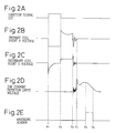
Figs. 2A to 2E are diagrams of waveforms at
each of the portions of the ignition circuit (Fig. 1) and
show, respectively, an ignition signal IGT, a voltage on
the grounding side of the primary coil (point P), a
voltage on the high-tension side of the secondary coil
(point S), and a voltage of an amplifier circuit (point
I). The abscissa represents time.
When the ignition signal IGT turns to the "H"
level and the transistor 13 is turned on at t1, the
voltage at point P drops. Immediately after t1, a
negative high-voltage pulse is generated at point S, that
is, on the high-tension side of the secondary coil.
However, the current is blocked by the reverse current-preventing
diode 15 from flowing into the spark plug 16
and the ionic current detecting unit 17.
When the ignition signal IGT turns to the "L"
level at t2 and the transistor 13 is cut off, the voltage
at point P abruptly rises, and a positive high-voltage
pulse is generated at point S.
The positive high-tension pulse is not blocked
by the reverse current-preventing diode 15 and flows into
the spark plug 16 to be discharged. It is prevented by
the protection diode 171 from flowing into the ionic
current detecting unit 17.
Furthermore, from t3 to t4 after the discharge
of the spark plug 16, LC resonance is triggered by energy
remaining in the ignition coil 11 due to parastic
inductance and parastic capacitance of the high-tension
cable 18 and the like.
The gas mixture in the cylinder is ignited by
the discharge of the spark plug 16, ions are generated in
the cylinder as the flame spreads, and an ionic current
starts flowing. The ionic current increases with an
increase in the pressure in the cylinder and decreases
with a decrease in the pressure in the cylinder.
When knocking occurs in the internal combustion
engine, knocking signals in a particular frequency band
(about 6 KHz) are superposed while the ionic current
decreases after having reached its peak.
In order to detect the knocking using the ionic
current, therefore, it is desired to detect only the
knocking signals in a particular frequency band and
reject other signals (e.g., LC resonance waves). For
this purpose, therefore, it is desired to provide a
knocking window which opens at t5 after spurious signals
disappear and closes at a suitable moment (e.g., ATDC
60°) after the ionic current has decreased, and to detect
the knocking based upon the output of the ionic current
detecting unit 17 while the knocking window is opened.
Fig. 3 is a diagram illustrating the
constitution of a device for detecting knocking by using
an ionic current. The output of the ionic current
detecting unit 17 is supplied to a processing unit 34
through a band-pass filter (BPF) unit 32 and an
integration (or peak-holding) unit 33. The operation of
the integration (or peak-holding) unit 33 is controlled
by a window which is opened after a predetermined period
determined depending upon the engine speed and the load,
and is closed at a moment corresponding to about 50° CA.
In order to maintain the accuracy for detecting
knocking irrespective of the conditions for detecting the
ionic current, "a method of determining abnormal
combustion and device therefor" which divides the ionic
current signal into one part containing a relatively
greater part of knocking frequency components and another
part containing relatively smaller part of knocking
frequency components, and detects knocking by comparing
the ratio of one part to another with a predetermined
reference level are already proposed (see Japanese
Unexamined Patent Publication (Kokai) No. 61-57830).
However, the spike noise due to corona
discharge of the spark plug 16 includes a wide frequency
spectrum and affects the knocking frequency. Besides,
the noise due to unstable combustion contains frequency
components very close to the knocking frequency band.
Therefore, it is not possible to accurately detect
knocking by simply dividing the ionic current signal into
two parts.
Fig. 4 is a diagram explaining the problems,
and shows the waveforms of ionic current signals in the
time domain and the frequency domain at a high-load
normal combustion state, at an intermediate-load normal
combustion state, at a state in which the knocking is
taking place, at a state in which the spike noise is
generated, and at a low-load normal combustion state.
That is, at the high-load and intermediate-load
normal combustion states, the ionic current signals
slowly increase and slowly decrease in the time domain
when the knocking window is being opened. In the
frequency domain, therefore, the level increases in the
low-frequency side and decreases in the high-frequency
side.
When knocking occurs, vibration components of
about 6 KHz are superposed on the ionic signal while the
knocking window is opened, and a peak appears near 6 KHz
in the frequency domain.
When spike noise is generated while the
knocking window is being opened, the level of the
frequency domain rises as a whole so that it becomes
difficult to extract a knocking peak from the ionic
signal.
While operating at a low-load, furthermore, the
flame in the combustion chamber is disturbed, and noise
with a relatively low frequency spectrum is superposed on
the ionic current. In the frequency domain, therefore,
the level in the low-frequency band rises so that it
becomes difficult to separate a knocking peak from the
spectra.
The present invention provides a device for
detecting knocking of an internal combustion engine,
which does not erroneously detect knocking even when a
spike noise or a noise due to disturbance in the flame in
the low-load zone is generated.
SUMMARY OF THE INVENTION
A device for detecting knocking in an internal
combustion engine according to a first invention
comprises:
According to this device, it is determined whether
or not knocking is occurring based upon the signals of
the knocking frequency components extracted from the
ionic current signals. When the low-load noise frequency
components lower than the knocking frequencies extracted
from the ionic current signals are higher than a
predetermined level, the determination of whether or not
knocking is occurring is prevented to prevent erroneous
determination of the occurrence of knocking.
BRIEF DESCRIPTION OF THE DRAWINGS
Fig. 1 is a diagram schematically illustrating an
ignition circuit in an internal combustion engine;
Figs. 2A to 2E are diagrams of voltage waveforms at
each of the portions of the ignition circuit;
Fig. 3 is a diagram illustrating the constitution of
a device for detecting knocking relying upon ionic
current;
Fig. 4 is a diagram illustrating the problems;
Fig. 5 is a diagram illustrating the constitution of
a device for detecting knocking of an internal combustion
engine according to an embodiment of the present
invention;
Fig. 6 is a flow chart of a knocking control
routine;
Figs. 7A and 7B are diagrams illustrating the
effects of the engine speed and the ignition timing upon
the ionic current signals;
Fig. 8 is a flow chart of a background calculation
processing; and
Fig. 9 is a flow chart of an ignition timing control
processing.
DETAILED DESCRIPTION OF THE PREFERRED EMBODIMENTS
Fig. 5 is a diagram illustrating the constitution of
a device for detecting knocking of an internal combustion
engine according to an embodiment of the present
invention. A mixture of air taken in through an air
cleaner 511 and a fuel injected from a fuel injection
valve 515, is supplied into a combustion chamber 501
defined by a piston 500, an intake valve 510 and an
exhaust valve 520 in an internal combustion engine 5.
The amount of the intake air is measured by an air
flow meter 512, and is adjusted by a throttle valve 514
disposed on an intake pipe 513.
The mixture compressed by the piston 500 is ignited
by the electric discharge of a spark plug 16 near the top
dead center of the piston 500, and expands to produce a
force that pushes down the piston 500.
Exhaust gases after the combustion are exhausted
into an exhaust pipe 521 through the exhaust valve 520,
and the oxygen concentration in the exhaust gas is
detected by an air-to-fuel ratio sensor 522 installed in
the exhaust pipe 521.
The temperature of the cooling water for cooling the
internal combustion engine 5 is detected by a cooling
water temperature sensor 504 inserted in a water jacket
503.
The ionic current flowing in the combustion chamber
501 is guided to the LC resonance masking unit 31 through
the spark plug 16 and the ionic current detecting unit
17. The output of the LC resonance masking unit 31 is
fed, through the band-pass filter 32 that permits the
passage of only those frequency components (6 KHz)
specific to the knocking, not only to the peak-holding
unit 33 that holds a peak in the output of the band-pass
filter 32 but also to a low-load noise peak-holding unit
331 through a low-load noise band-pass filter 321 that
permits the passage of only those frequency components
(about 4 KHz) specific to the noise caused by unstable
flame while the low-load operation. Because the spike
noise has a wide frequency spectrum, the output of the
low-load noise band-pass filter 321 rises when the spike
noise is generated. This means that the spike noise can
also be detected by fetching the output of the low-load
noise peak-holding unit 331.
The peak-holding unit 33 and the low-load peak-holding
unit 331 are connected to a processing unit 55.
The processing unit 55 is a microcomputer system
which is constituted by an analog input interface (I/F)
551, a digital input I/F 552, an output I/F 553, a CPU
554, a memory 555 and a bus 550.
That is, the outputs of the peak-holding unit 33 and
the low-load noise peak-holding unit 331 are connected to
the analog input I/F 551. The air flow meter 512,
cooling water temperature sensor 504 and air-to-fuel
ratio sensor 522 to the analog input I/F 551 are further
connected.
The output I/F 553 outputs a valve opening command
to the fuel injection valve 515 and, further, outputs an
ignition command signal IGT and an ionic current fetching
control signal.
That is, the ignition command signal IGT is boosted
through the ignition coil 11, and is sent to the spark
plug 16 through the distributor 505. The distributor 505
contains a crank angle sensor 506 which generates a pulse
signal every, for example, 30° CA (crank angle) and a
reference angle sensor 507 which generates a pulse signal
every, for example, 720° CA. Outputs of these sensors
are supplied by the processing unit 55 through the
digital input I/F 552 and are used for calculating the
engine speed Ne, for controlling the timings for opening
and closing the fuel injection valve 515 and for
controlling the timing for outputting the ignition
command signal IGT.
When the LC resonance is taking place, the ionic
current fetching control signal turns off the LC
resonance masking unit 31 to prevent the LC resonance
wave from being fetched, and the ionic current fetching
control signal is supplied to the peak-holding unit 33
and to the low-load noise peak-holding unit 331 to permit
the operations of the peak-holding unit 33 and the low-load
noise peak-holding unit 331 while the knocking
window is being opened.
Fig. 6 is a flow chart of a knocking control routine
executed by the CPU 554 in the processing unit 55. This
routine is executed for every ignition timing operation
in each cylinder of the internal combustion engine 5, and
the variable is determined for each cylinder.
A peak VKN of the knocking frequency held by the
peak-holding unit 33 and a peak VNN of the noise
frequency held by the low-load noise peak-holding unit
331 are fetched at step 60.
At step 61, it is determined whether or not the peak
VNN of the noise frequency is higher than a predetermined
threshold level VTH, i.e., it is determined whether or
not a noise frequency component higher than the
predetermined level is detected from the ionic current.
When the determination at step 61 is negative, i.e.,
when a noise frequency component greater than the
predetermined level is not detected from the ionic
current, the control proceeds to step 62 where it is
determined whether or not the ratio (VKN/VNN) of the peak
VNN of noise frequency to the peak VKN of knocking
frequency is bigger than the predetermined ratio RTH.
Note that the predetermined ratio RTH is determined
as a function of the engine speed Ne and the ignition
timing TI, and becomes smaller as the engine speed is
increased and the ignition timing is advanced.
RTH ← RTH (Ne, TI)
The reason why RTH becomes smaller as the engine speed in
increased and the ignition timing is advanced is as
follows.
Figs. 7A and 7B are diagrams illustrating the
effects of the engine speed and the ignition timing upon
the ionic current signal, wherein Fig. 7A shows the
waveform in the time domain and Fig. 7B shows the
waveform in the frequency domain. Broken lines represent
the effects when the engine speed is low (e.g., 2000 rpm)
or when the ignition timing is delayed, and the solid
lines represent the effects when the engine speed is high
(e.g., 6000 rpm) or when the ignition timing is advanced.
That is, in the time domain, a peak of the ionic
current signal that occurs after the gas mixture has been
ignited becomes higher and occurs earlier when the engine
speed is increased and the ignition timing is advanced.
When the knocking occurs, vibration with about 6 KHz is
superposed while the ionic current is reduced after it
has reached its peak.
In the frequency domain, the level is reduced with
an increase in the frequency, and the peak of knocking
appears at 6 KHz. If the strength of knocking is the
same, the peak at 6 KHz maintains its intensity. The
frequency spectrum shifts toward the higher frequencies
when the engine speed is increased or the ignition timing
is advanced.
Therefore, the ratio VKNH/VNNH of the peak VNNH at 4
KHz to the peak VKNH at 6 KHz when the engine speed is
increased or when the ignition timing is advanced,
becomes smaller than the ratio VKNL/VNNL when the engine
speed is decreased or when the ignition timing is
delayed.
When the determination at step 62 is affirmative,
the control proceeds to step 63 where the background
calculating subroutine is executed because the detection
of knocking is allowed. This subroutine will be
described later.
At step 64, it is determined whether or not the peak
VKN of the ionic current is larger than the background
VGB multiplied by a first predetermined coefficient K1.
When the determination is affirmative, it is determined
at step 65 whether or not the peak VKN of the ionic
current is larger than the background VBG multiplied by a
second predetermined coefficient K2. It is assumed that,
0 < K1 < K2.
When the determination at step 65 is affirmative,
i.e., when the level of knocking is high, an ignition
timing correction factor ΔTI is set to a predetermined
large delay angle (-DTH) at step 66, and the control
proceeds to step 69.
When the determination at step 65 is negative, i.e.,
when it is determined that the level of knocking that is
taking place is low, the ignition timing correction
factor ΔTI is set to a predetermined small delay angle (-DTL)
at step 67, and the control proceeds to step 69.
When the determination at step 61 is affirmative or
when the determination at step 62 is negative, the noise
frequency components are so great that the knocking
frequency components may be buried therein, and the
occurrence of knocking may not be properly detected. In
this case, it is regarded that knocking is not occurring,
and the ignition timing correction factor ΔTI is set to a
predetermined advancing angle LT at step 68, and the
control proceeds to step 69.
When the determination at step 64 is negative, i.e.,
when it is determined that the knocking is not really
taking place, the control proceeds to step 68.
It is assumed that 0 < LT < DTL < DTH. This is so
that when no knocking is occurring, the ignition timing
is gradually advanced and when knocking occurs, the
ignition timing is delayed by a large amount to suppress
the knocking. In this embodiment, furthermore, the angle
is delayed by a very large amount when the level of
knocking is high to enhance the effect of suppression.
An ignition timing control subroutine is executed at
step 69 to terminate the routine. The ignition timing
control subroutine will be described later.
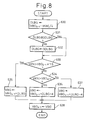
Fig. 8 is a flow chart of a background calculation
subroutine executed at step 63 in the knocking control
routine. An updated amount DLBG is calculated at step
630 according to the following formula,
DLBG ← VBGi-1 - VKN/4
where VBGi-1 is a background calculated for the
previous time, and the updated quantity DLBG is
calculated as a value one-fourth of the absolute value of
a difference between the background calculated at the
previous execution and a peak value VKN at the present
execution.
At steps 631 and 632, the updated amount DLBG is
limited to a predetermined upper-limit guard value GDLBG.
At steps 633 and 634, it is determined whether or
not the peak value VKN at this execution is larger than
the product of a predetermined coefficient (e.g., 1.5)
which is larger than 1.0 and VBGi-1, smaller than the
product and larger than VBGi-1, or smaller than VBGi-1.
When the peak value VKN is larger than VBGi-1
multiplied by the predetermined coefficient, the
background VBG is updated at step 635 according to the
following formula,
VBG ← VBGi-1 + DLBG
When the peak value VKN is smaller than VBGi-1
multiplied by predetermined coefficient but is larger
than VBGi-1, the background VBG is updated at step 636
according to the following formula,
VBG ← VBGi-1 + DLBG + α
When the peak value VKN is smaller than VBGi-1, the
background VBG is updated at step 637 according to the
following formula,
VBG ← VBGi-1 + DLBG - α
where α is an adjustment coefficient for setting the
background VBG to be limited within a suitable
range.
Finally, at step 638, the VBGi-1 is set to the
background VBG calculated at this execution to be ready
for the operation of the next execution, and this
subroutine is terminated.
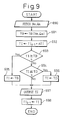
Fig. 9 is a flow chart of the ignition timing
control processing executed at the step 69 in the
knocking control routine. The engine speed Ne determined
depending upon a pulse output from the crank angle sensor
506 and the intaken air amount Qa detected by the air
flow meter 512, are fetched at step 690, and a reference
ignition timing TB is calculated at step 691 as a
function of the engine speed Ne and the intaken air
amount Qa according to the following formula,
TB ← TB (Ne, Qa)
At step 692, the ignition timing correction value
ΔTI is added to the ignition timing TIi-1 calculated in
the previous execution, to calculate the ignition timing
TI of this execution,
TI ← TIi-1 + ΔTI
In this embodiment, the ignition timing is advanced
when a positive number is added and is delayed when a
positive number is subtracted.
At steps 693 and 694, it is determined whether or
not the ignition timing TI of this execution is between
the reference ignition timing TB which is the maximum
advanced ignition timing and a predetermined maximum
delayed ignition timing TD.
That is, when the ignition timing TI at this
execution is more advanced than the reference ignition
timing TB, the determination at step 693 is affirmative,
the ignition timing TI at this execution is replaced by
the reference ignition timing TB at step 695, and the
control proceeds to step 697.
Conversely, when the ignition timing TI at this
execution is more delayed than the maximum delayed
ignition timing TD, the determination at step 694 is
negative, the ignition timing TI at this execution is
replaced by the maximum delayed ignition timing TD at
step 696, and the control proceeds to step 697. When the
ignition timing TI at this execution is between the
reference ignition timing TB and the maximum delayed
ignition timing TD, the control directly proceeds to step
697.
At step 697, the ignition command signal IGT is
output to the ignition coil 11 through the output I/F
553, the ignition timing TIi-1 calculated at the previous
execution is updated to the ignition timing TI at this
execution to be ready for the calculation of the next
execution, and this subroutine is terminated.
In the above-mentioned embodiment, the device for
detecting knocking in an internal combustion engine is
constituted by hardware circuits including the band-pass
filter 32, the peak-holding unit 33, the low-load noise
band-pass filter 321 and the low-load noise peak-holding
unit 331. However, it is also possible to supply the
outputs of the LC resonance masking unit 31 directly to
the computer, to analyze the frequency by using FFT
algorithms and the like, and to divide the outputs into
noise components and knocking components based upon a
frequency spectral pattern.