EP0825455B1 - Failure determination device of radar apparatus - Google Patents
Failure determination device of radar apparatus Download PDFInfo
- Publication number
- EP0825455B1 EP0825455B1 EP97301592A EP97301592A EP0825455B1 EP 0825455 B1 EP0825455 B1 EP 0825455B1 EP 97301592 A EP97301592 A EP 97301592A EP 97301592 A EP97301592 A EP 97301592A EP 0825455 B1 EP0825455 B1 EP 0825455B1
- Authority
- EP
- European Patent Office
- Prior art keywords
- signal
- frequency
- modulation
- modulator
- circuit
- Prior art date
- Legal status (The legal status is an assumption and is not a legal conclusion. Google has not performed a legal analysis and makes no representation as to the accuracy of the status listed.)
- Expired - Lifetime
Links
Images







Classifications
-
- G—PHYSICS
- G01—MEASURING; TESTING
- G01S—RADIO DIRECTION-FINDING; RADIO NAVIGATION; DETERMINING DISTANCE OR VELOCITY BY USE OF RADIO WAVES; LOCATING OR PRESENCE-DETECTING BY USE OF THE REFLECTION OR RERADIATION OF RADIO WAVES; ANALOGOUS ARRANGEMENTS USING OTHER WAVES
- G01S7/00—Details of systems according to groups G01S13/00, G01S15/00, G01S17/00
- G01S7/02—Details of systems according to groups G01S13/00, G01S15/00, G01S17/00 of systems according to group G01S13/00
- G01S7/40—Means for monitoring or calibrating
- G01S7/4052—Means for monitoring or calibrating by simulation of echoes
- G01S7/4056—Means for monitoring or calibrating by simulation of echoes specially adapted to FMCW
-
- G—PHYSICS
- G01—MEASURING; TESTING
- G01S—RADIO DIRECTION-FINDING; RADIO NAVIGATION; DETERMINING DISTANCE OR VELOCITY BY USE OF RADIO WAVES; LOCATING OR PRESENCE-DETECTING BY USE OF THE REFLECTION OR RERADIATION OF RADIO WAVES; ANALOGOUS ARRANGEMENTS USING OTHER WAVES
- G01S13/00—Systems using the reflection or reradiation of radio waves, e.g. radar systems; Analogous systems using reflection or reradiation of waves whose nature or wavelength is irrelevant or unspecified
- G01S13/88—Radar or analogous systems specially adapted for specific applications
- G01S13/93—Radar or analogous systems specially adapted for specific applications for anti-collision purposes
-
- G—PHYSICS
- G01—MEASURING; TESTING
- G01S—RADIO DIRECTION-FINDING; RADIO NAVIGATION; DETERMINING DISTANCE OR VELOCITY BY USE OF RADIO WAVES; LOCATING OR PRESENCE-DETECTING BY USE OF THE REFLECTION OR RERADIATION OF RADIO WAVES; ANALOGOUS ARRANGEMENTS USING OTHER WAVES
- G01S13/00—Systems using the reflection or reradiation of radio waves, e.g. radar systems; Analogous systems using reflection or reradiation of waves whose nature or wavelength is irrelevant or unspecified
- G01S13/02—Systems using reflection of radio waves, e.g. primary radar systems; Analogous systems
- G01S13/06—Systems determining position data of a target
- G01S13/08—Systems for measuring distance only
- G01S13/32—Systems for measuring distance only using transmission of continuous waves, whether amplitude-, frequency-, or phase-modulated, or unmodulated
- G01S13/34—Systems for measuring distance only using transmission of continuous waves, whether amplitude-, frequency-, or phase-modulated, or unmodulated using transmission of continuous, frequency-modulated waves while heterodyning the received signal, or a signal derived therefrom, with a locally-generated signal related to the contemporaneously transmitted signal
- G01S13/345—Systems for measuring distance only using transmission of continuous waves, whether amplitude-, frequency-, or phase-modulated, or unmodulated using transmission of continuous, frequency-modulated waves while heterodyning the received signal, or a signal derived therefrom, with a locally-generated signal related to the contemporaneously transmitted signal using triangular modulation
-
- G—PHYSICS
- G01—MEASURING; TESTING
- G01S—RADIO DIRECTION-FINDING; RADIO NAVIGATION; DETERMINING DISTANCE OR VELOCITY BY USE OF RADIO WAVES; LOCATING OR PRESENCE-DETECTING BY USE OF THE REFLECTION OR RERADIATION OF RADIO WAVES; ANALOGOUS ARRANGEMENTS USING OTHER WAVES
- G01S13/00—Systems using the reflection or reradiation of radio waves, e.g. radar systems; Analogous systems using reflection or reradiation of waves whose nature or wavelength is irrelevant or unspecified
- G01S13/88—Radar or analogous systems specially adapted for specific applications
- G01S13/93—Radar or analogous systems specially adapted for specific applications for anti-collision purposes
- G01S13/931—Radar or analogous systems specially adapted for specific applications for anti-collision purposes of land vehicles
-
- G—PHYSICS
- G01—MEASURING; TESTING
- G01S—RADIO DIRECTION-FINDING; RADIO NAVIGATION; DETERMINING DISTANCE OR VELOCITY BY USE OF RADIO WAVES; LOCATING OR PRESENCE-DETECTING BY USE OF THE REFLECTION OR RERADIATION OF RADIO WAVES; ANALOGOUS ARRANGEMENTS USING OTHER WAVES
- G01S7/00—Details of systems according to groups G01S13/00, G01S15/00, G01S17/00
- G01S7/02—Details of systems according to groups G01S13/00, G01S15/00, G01S17/00 of systems according to group G01S13/00
- G01S7/40—Means for monitoring or calibrating
- G01S7/4052—Means for monitoring or calibrating by simulation of echoes
- G01S7/406—Means for monitoring or calibrating by simulation of echoes using internally generated reference signals, e.g. via delay line, via RF or IF signal injection or via integrated reference reflector or transponder
- G01S7/4069—Means for monitoring or calibrating by simulation of echoes using internally generated reference signals, e.g. via delay line, via RF or IF signal injection or via integrated reference reflector or transponder involving a RF signal injection
Definitions
- This invention relates to an FM-CW (Frequency Modulated Continuous Wave) radar apparatus which transmits a high frequency signal modulated (FM modulated) by a modulation signal, receives a reflected signal back from a target object, and converts the received reflected signal, by using a signal which is obtained by splitting a part of the sending signal as a local oscillation signal for a receiver and more particularly to the FM-CW radar apparatus being installed in a vehicle, which is preferably used to avoid a collision by calculating relative speed and distance from a target object.
- FM-CW Frequency Modulated Continuous Wave
- a safety device such as a monitoring system between vehicles to obtain information about a collision in advance in order to decrease the number of vehicle collision accidents, is required for installing in vehicles at a low cost.
- an FM-CW radar system (frequency modulation continuous wave radar system ) is used as a radar system which can measure the relative speed and distance to a target object.
- This radar system can measure the relative speed and distance by a simple signal processing circuit, and can realize a sending/receiving apparatus at a low cost, so that this system has been used as a collision avoidance radar system for a vehicle.
- Fig. 1 and 2 an operating principle of the FM-CW radar system is shown.
- Fig. 3 a conventional FM-CW radar apparatus is illustrated. Next, the principle of the FM-CW radar system will be explained.
- an oscillating signal outputted by an oscillator 2 is FM-modulated by a sawtooth wave of several hundreds of Hz provided from a modulation signal generator 1, and the FM modulated wave is transmitted from a sending antenna 5.
- a reflected signal from the target object is received by a receiving antenna 6, and is input to a frequency convertor 7, such as a mixer.
- the frequency convertor 7 detects, as an FM detector, the above described received signal by utilizing the FM modulated wave outputted from the oscillator 2 as a local oscillation signal.
- the reflected wave from the target object produces a frequency shift (beat) from the sending signal as shown in Figs.
- This beat frequency element fb is represented by ( distance frequency fr depending on the distance ) ⁇ ( speed frequency fd depending on the speed ). Therefore, the distance and the relative speed can be measured based on the frequency shift.
- ⁇ is a modulation width
- T is a modulation wave period
- c is the speed of light
- R is a distance from the obstacle (target object)
- f 0 is a sending central frequency
- v is a relative speed of the obstacle (target object).
- a modulation wave period should.be set to be approximately 1 ⁇ 10 -3 s (second) and the modulation width should be set to be approximately 100 MHz in order to get sufficient distance measurement accuracy, since the measurement distance is 100 m (meter) at the most, and the relative speed may be 100 km/h (kilo meter/ hour).
- a millimeter wave band should be used as a sending frequency band in order to get sufficient relative speed measurement accuracy. For example, when the modulation wave period is 1.33 x 10 -3 s, the modulation width is 75 MHz, and the sending frequency is 60 GHz, distance resolving power becomes 1 m and speed resolving power becomes 6.75 km/h.
- the method As a method for detecting a failure in a high frequency circuit of the radar system according to the conventional FM-CW radar, the method has been considered in which a failure is detected by monitoring current values or voltage values applied to parts of each high frequency circuit.
- an FM-CW radar apparatus at a low price which is able to detect abnormal operation and a performance deterioration based on the characteristic deterioration of a high frequency circuit.
- US-A-3 932 870 discloses a radar apparatus according to the preamble of claim 1. It provides an on-line test circuit for use in a Doppler radar alarm system, operative to supervise the system operation continuously without affecting normal operation.
- a local oscillator provides two split signals, one of which is used to generate a sending-signal and the other being fed to a mixer along with a received signal.
- An FM test signal applied to the local oscillator causes modulation of the sending signal, which causes a detectable sub-Doppler signal in the output of the mixer.
- EP-A-0 527 443 by the present applicant discloses a FM-CW radar device having high efficiency, low cost and a high temperature stability.
- a sending signal from a VCO is split with one part being transmitted and the other sent to a frequency converter for use as a local oscillating wave; however, there is no disclosure of applying modulation to the sending signal prior to splitting.
- the present invention relates to a failure determination device of a radar apparatus which transmits a high frequency signal modulated by a modulation signal, receives a reflected signal from a target object, and converts the aforementioned received reflected signal by using a signal which is split from the sending signal.
- a radar apparatus for sending a signal towards and receiving a reflected signal back from a target object, comprising: an oscillator to which is applied a frequency modulation; a mixer for converting the received reflected signal by mixing it with another signal; a detection circuit for detecting modulation of the converted signal from the mixer; and a failure determination circuit for determining whether or not a failure has occurred, based on the modulation detected by the detection circuit; characterised in that: said frequency modulation is for use in detecting the relative speed and/or distance of the target object and the radar apparatus; a modulator receives the frequency-modulated signal generated by the oscillator, and applies a remodulation for use in failure to said signal detection, to form a remodulated signal; a splitter splits off part of the remodulated signal prior to sending the remodulated signal; said mixer converts the received reflected signal by mixing it with said split part of the remodulated signal, thereby generating signal elements including said remodulation
- the present invention it becomes possible to detect the abnormal operation and the performance deterioration based on the characteristic deterioration of the high frequency circuit before the radar apparatus fails completely.
- a failure determination method applied to a radar apparatus comprising steps of: applying a frequency modulation to a signal generated by an oscillator; sending the frequency-modulated signal towards a target object after splitting off part of the frequency-modulated signal; receiving a reflected signal back from the target object; frequency-converting the received reflected signal by using the split part of the frequency-modulated signal; detecting modulated elements from the converted signal; and determining whether or not a failure has occurred, based on the modulated elements detected; characterised in that said frequency modulation is for use in determining the relative speed and/or distance of the target object and the radar apparatus, and by the further steps of: applying a remodulation to the frequency-modulated signal by a modulator prior to the splitting, for use in failure detection, whereby said detecting step includes detection of said remodulation; and wherein said determining step determines whether or not a failure has occurred based on said remodulation detected in said detecting step.
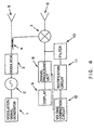
- Fig. 4 is a block diagram of the first embodiment of the present invention.
- a modulation signal generator 1 generates a sawtooth wave signal for frequency modulation (FM modulation).
- a voltage controlled oscillator 2 generates the signal to be modulated in the millimeter wave band which is output from the radar system.
- a modulator 3 applies a second modulation (remodulation) for detecting a failure.
- a directional coupler 4 splits the signal from the voltage controlled oscillator 2 to the sending signal for the sending antenna 5 and the local oscillation signal for a frequency convertor 7.
- a sending antenna 5 efficiently radiates the frequency modulated signal output from the voltage controlled oscillator 2.
- the receiving antenna 6 efficiently receives the signal reflected from a target object.
- the frequency convertor 7 mixes the local oscillation signal from the directional coupler 4 and the reflected signal from the target object which is received by the receiving antenna 6, and generates the signal elements containing the relative speed and the distance information between the target object and the radar apparatus.
- a signal processing unit 8 detects the relative speed and the distance information from the signal elements output from the frequency convertor 7, and outputs data necessary for display to a display 9.
- the display 9 displays the display data output from the signal processing unit 8.
- a filter 10 has the band width in which only the modulated frequency, for checking the operation in a high frequency circuit system in the radar apparatus, can pass.
- a rectification circuit 11 outputs the modulated signal to a voltage comparison circuit 12 by converting it to a direct current signal.
- the voltage comparison circuit 12 compares a reference level which is previously set with a detection level of the signal detected in the high frequency circuit system, and sends an alarm signal to a CPU (not shown in this figure), when the detected level becomes lower than the reference level.
- the modulator 3 corresponds to the modulator recited in the claims.
- the filter 10, the rectification circuit 11, and the voltage comparison circuit 12 correspond to the detection circuit recited in the claims, and the signal processing unit 8 corresponds to the failure determination circuit recited in the claims.
- the performance deterioration and the abnormal operation resulted from the characteristic deterioration of a high frequency circuit can be detected before the radar apparatus fails completely.
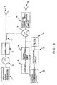
- Fig. 5 is a block diagram of the second embodiment of the present invention.
- a sending signal output attenuation circuit 13 is installed between the directional coupler 4 and the sending antenna 5 for the component of the first embodiment of the present invention shown in Fig. 4.
- the sending signal output attenuation circuit 13 corresponds to the output attenuation circuit recited in the claims.
- the sending signal output can be attenuated when a failure determination mode is chosen, so that the influences external to the radar system can be attenuated.
- Fig.6 is a block diagram of the third embodiment of the present invention.
- a receiving signal input attenuation circuit 14 is installed between the receiving antenna 6 and the frequency convertor 7 in the first embodiment of the present invention shown in Fig. 4.
- the receiving signal input attenuation circuit 14 corresponds to the input attenuation circuit recited in the claims.
- the received signal is able to be attenuated when the failure determination mode is chosen,so that the influences external to the radar are able to be attenuated.
- the modulation frequency of the signal for operation of the failure determination mode is able to be set in such a way that it is a different frequency from the modulation frequency of the frequency modulation used to generate the sending signal.
- the frequency modulation or the phase modulation other than the amplitude modulation is able to be used as a signal modulation method for the failure determination.
- the amplitude modulation is able to be realized by changing the gain of an amplifier, for example, or switching the signal.
- Fig. 7 is a block diagram of the first preferred embodiment of the present invention.
- the FM-CW radar apparatus shown in Fig. 7 includes the modulation signal generator 1, the voltage controlled oscillator 2, the modulator 3, the directional coupler 4, and the sending antenna 5 as a sending system, the receiving antenna 6 and the frequency convertor 7 as a receiving system, and the signal processing unit 8 (comprising the filter 19, A/D convertor 20, DSP 21, and CPU 22), the display 9, the filter 10, the rectification circuit 11, and the comparator 23 as a signal processing system.
- the modulation signal generator 1 generates the sawtooth wave signal for frequency modulation.
- the voltage controlled oscillator 2 generates the frequency-modulated signal of the millimeter wave band for the radar output.
- the modulator 3 generates the signal for the failure detection.
- the directional coupler 4 receives the millimeter wave signal from the modulator 3 as the local oscillation signal for the sending antenna 5 and the frequency convertor 7.
- the sending antenna 5 effectively radiates the signal output from the directional coupler 4.
- the receiving antenna 6 effectively receives the signal reflected from the target object.
- the frequency convertor 7 mixes the local oscillation signal from the directional coupler 4 with the signal received from the receiving antenna 6, generates the signal elements containing the relative speed and the distance information between the target object and the radar apparatus, and in addition generates the failure detection signal.
- the signal processing unit 8 detects the relative speed and the distance information from the signal elements output from the frequency convertor 7, and outputs the data necessary for display to the display 9.
- the filter 19 extracts only the beat frequency element (as shown in Figs. 1 and 2).
- A/D convertor 20 converts an analog output signal from the filter 19 into a digital signal.
- DSP 21 extracts the beat frequency element by operating an FFT (Fast Fourier Transformation) analysis for the digital signal output from the A/D convertor 20, and calculates the distance and the relative speed based on the aforementioned equation (1).
- CPU 22 operates failure detection processing by monitoring the output from the comparator 23, and data display processing for the display 9. Next, the display 9 displays the display data output from the signal processing unit 8.
- the filter 10 filters the signal element necessary for the failure detection among the signal elements output from the frequency convertor 7.
- the rectification circuit 11 converts an alternating current signal from the filter 10 into a direct current signal.
- the comparator 23 compares the failure detection signal output from the rectification circuit 11 with a reference signal previously set.
- the FM-CW radar apparatus comprising the above described elements operates as follows.
- the sawtooth wave generated in the modulation signal generator 1 is input to the voltage controlled oscillator 2 in order to generate the frequency modulated wave.
- this signal is again modulated (remodulated) by the modulator 3.
- the modulating method is AM modulation
- the output signal from the modulator 3 is represented by the following equation A ( 1 + B ) s i n [ ⁇ , t + ⁇ s (t) dt] where, (1 + B) is an AM modulation element, and the modulated frequency is approximately 500 KHz (Kilo Hertz) to 1 MHz (Mega Hertz).
- This signal is input to the frequency convertor 7 as the local oscillation signal from the directional coupler 4.
- the rectification circuit 11 converts this signal Sdet into a direct current signal and the comparator 23 compares this signal with the reference voltage, it becomes possible to detect whether or not a failure situation exists.
- the reference voltage is set to be a value where a seasonal change and a temperature change are added to a value of a direct current signal generated when the radar apparatus operates correctly.
- CPU 22 determines that the radar apparatus is operating abnormally when the comparator 23 detects that the voltage of the direct current signal output from the rectification circuit 11 is lower than the reference voltage.
- the voltage of the direct current signal output from the rectification circuit 11 becomes lower, since the absolute level of the signal output from the frequency convertor 7 becomes lower as a whole when the conversion loss is increased in the frequency convertor 7. Further, the voltage of the direct current signal output from the rectification circuit 11 also becomes lower, since the input level of the signal input into the frequency convertor 7 from the directional coupler 4 becomes lower when the output voltage of the modulation signal generator 1 becomes lower. Therefore, the lower voltage of the direct current signal output from the rectification circuit 11 shows that the sensitivity of the signal has deteriorated in the high frequency circuit, in either the receiving side or the sending side of the radar apparatus. Then, this indicates that the limitation in the detected distance of the vehicle ahead becomes shorter.
- Fig. 8 is an operating flowchart showing the processing of DSP 21.
- DSP 21 operates the FFT (Fast Fourier Transformation) analysis for the digital signal output from A/D converter 20 (step 30 in Fig. 8 ).
- DSP 21 identifies the peak frequency for the FFT frequency output (step 31). Then, DSP 21 limits the number of the peaks to be used (step 33) by calculating a threshold value for the level of the peak frequency (step 32).
- FFT Fast Fourier Transformation
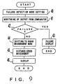
- Fig.9 is an operating flowchart showing the . processing in CPU 22.
- CPU 22 sets the current mode to be the failure detection mode (step 40 in Fig. 9 ).
- the setting timing in which the current mode is set to be the failure detection mode is the timing at which a vehicle engine has just been started, or when the radar apparatus has just been switched on, for example.
- CPU 22 monitors the output voltage of the comparator 23 (step 41), and determines whether or not a failure has occurred by determining whether or not the output voltage of the comparator 23 is lower than the reference voltage (step 42).
- CPU 22 displays the failure on the display 9 if it determines that a failure has occurred (step 43).
- step 44 it changes the failure detection mode to the radar measurement mode (step 44) if it determines that a failure has not occurred, and sets DSP 21 to measure the distance and relative speed (step 45). As a result, the distance and the relative speed calculated by DSP 21 are displayed on the display 9 (step 46).
- abnormal working or a performance deterioration based on the characteristic deterioration of the high frequency circuits can be detected before the function of the FM-CW radar apparatus fails completely.
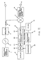
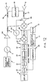
- Fig. 10 is a block diagram of the second preferred embodiment of the present invention. Items with same reference number as those in Fig. 7 have the same function and their description is omitted here.
- a sending signal output attenuation circuit 13 is installed between the directional coupler 4 and the sending antenna 5 in order to prevent output of the sending signal. According to the structure of this embodiment, the receiving of the signal resulting from the reflected wave from the target object is prevented no matter how close the target object becomes to the radar apparatus.
- the same effect for the failure signal detection, etc., as the aforementioned first embodiment is realized based on the same principle as the aforementioned first preferred embodiment, although the sending signal output attenuation circuit 13 is installed in the sending system.
- Fig.11 is a block diagram of the third preferred embodiment of the present invention. Items with the same reference number as those in Fig. 7 have the same function and their description is omitted here.
- a receiving signal input attenuation circuit 14 is installed between the receiving antenna 6 and the frequency convertor 7 in order to prevent the output of the receiving signal. According to the structure of this embodiment, the signal resulting from the reflected wave from the target object is prevented no matter how close the target object becomes to the radar apparatus.
- the same effect for the failure signal detection, etc., as the aforementioned first preferred embodiment can be realized based on the same principle as the aforementioned first preferred embodiment, although the receiving signal input attenuation circuit 14 is installed in the receiving system.
- Fig. 12 is a block diagram of a radar apparatus useful for understanding a fourth preferred embodiment, but which is not itself in accordance with the present invention. It is an adaptation of a FM-CW radar apparatus developed by FUJITSU and described in Japanese patent application (Tokkaihei) 5-040169. Items already referenced in FIG. 7 have the same function and their description is omitted here.
- This heterodyne type FM-CW radar apparatus is formed by installing the sending signal amplifier 24 between the voltage controlled oscillator 2 and the directional coupler 4, the receiving signal amplifier 25 between the directional coupler 17 and the frequency convertor 7, the filter 28 and the second frequency convertor 27 between the frequency convertor 7 and the signal processing unit 8, and the switching signal source 26. Therefore, the signal which is converted to an intermediate frequency element by the second frequency convertor 27 is input to the signal processing unit 8 after only the frequency element corresponding to the beat frequency has been passed by the filter 28, thus providing better reduction of noise than the conventional technologies.
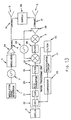
- Fig. 13 shows the another preferred embodiment to which the present invention is applied in the FM-CW radar apparatus disclosed in the prior art of the Japanese Patent application mentioned above. Items with the same reference number as those in Fig. 7 have the same function and their description is omitted here.
- the heterodyne type FM-CW radar apparatus is formed in the same manner as in Fig. 12 described above.
- the same effect for the failure signal detection, etc., as the aforementioned first preferred embodiment can be realized based on the same principle as the radar apparatus of Fig. 12, although the FM-CW radar apparatus forms the heterodyne type of embodiment by installing the sending signal amplifier 24 between the modulator 3 and the directional coupler 4, the receiving signal amplifier 25 between the directional coupler 17 and the frequency convertor 7, the second frequency convertor 27 and the filter 28 between the frequency convertor 7 and the signal processing unit 8, and the switching signal source 26.
- the failure detection frequency can be determined very easily by selecting a frequency different from the modulation frequency which is used for the distance and relative speed measurement for the radar apparatus, as the modulation frequency for the failure detection in the aforementioned respective preferred embodiments.
- the switching circuit for switching at the rate of the failure detection frequency can be used, other than AM modulation.
- This switching circuit can be considered as a special case of AM modulation because the amplitude is modulated to either 1 or 0.
- a PIN (Positive Intrinsic Negative) diode is used, for example, or three-terminal devices such as GaAs, MESFET (Metal-Semiconductor FET) or HEMT (High Electron Mobility Transistor) are used by switching a drain current (drain voltage).
- a gain attenuator or a switching circuit can be used.
- the filter 19, A/D convertor 20, and DSP 21 can be used functionally to replace the filter 10, the rectification circuit 11, and the comparator 23, respectively.
- FIG. 14 is an operating flowchart showing a determination logic process of CPU 22 for a temperature change, when that embodiment is applied.
- CPU 22 obtains a temperature value that a designated temperature sensor has detected (step 50 in Fig. 14).
- it reads a threshold voltage corresponding to the detected temperature from the designated ROM (Read Only Memory) table (step 51).
- the obtained value is set as the reference voltage of the comparator 23 (step 52).
- CPU 22 monitors the sensor (step 53).
- the abnormality processing is executed if an abnormality of the sensor is detected (steps 54 and 55).
- an embodiment can be formed in which the comparator 23 is made dependent directly on temperature by using a thermistor.
Landscapes
- Engineering & Computer Science (AREA)
- Radar, Positioning & Navigation (AREA)
- Remote Sensing (AREA)
- Physics & Mathematics (AREA)
- Computer Networks & Wireless Communication (AREA)
- General Physics & Mathematics (AREA)
- Signal Processing (AREA)
- Electromagnetism (AREA)
- Radar Systems Or Details Thereof (AREA)
Description
- This invention relates to an FM-CW (Frequency Modulated Continuous Wave) radar apparatus which transmits a high frequency signal modulated (FM modulated) by a modulation signal, receives a reflected signal back from a target object, and converts the received reflected signal, by using a signal which is obtained by splitting a part of the sending signal as a local oscillation signal for a receiver and more particularly to the FM-CW radar apparatus being installed in a vehicle, which is preferably used to avoid a collision by calculating relative speed and distance from a target object.
- Recently, the number of accidents such as a vehicle collision shows a tendency to increase year by year as the number of vehicles on the roads increases. Thus, a safety device, such as a monitoring system between vehicles to obtain information about a collision in advance in order to decrease the number of vehicle collision accidents, is required for installing in vehicles at a low cost.
- Up to now, an FM-CW radar system (frequency modulation continuous wave radar system ) is used as a radar system which can measure the relative speed and distance to a target object. This radar system can measure the relative speed and distance by a simple signal processing circuit, and can realize a sending/receiving apparatus at a low cost, so that this system has been used as a collision avoidance radar system for a vehicle.
- In Fig. 1 and 2, an operating principle of the FM-CW radar system is shown. In Fig. 3, a conventional FM-CW radar apparatus is illustrated. Next, the principle of the FM-CW radar system will be explained.
- As shown in Fig. 3, an oscillating signal outputted by an
oscillator 2 is FM-modulated by a sawtooth wave of several hundreds of Hz provided from amodulation signal generator 1, and the FM modulated wave is transmitted from a sendingantenna 5. Then, a reflected signal from the target object is received by areceiving antenna 6, and is input to afrequency convertor 7, such as a mixer. Thefrequency convertor 7 detects, as an FM detector, the above described received signal by utilizing the FM modulated wave outputted from theoscillator 2 as a local oscillation signal. As a result, the reflected wave from the target object produces a frequency shift (beat) from the sending signal as shown in Figs. 1 and 2, depending on the distance between the radar system and the target object and on the Doppler shift based on the relative speed. This beat frequency element fb is represented by ( distance frequency fr depending on the distance )±( speed frequency fd depending on the speed ). Therefore, the distance and the relative speed can be measured based on the frequency shift. - Here, the following well-known equations are shown.
- Using this principle in a vehicle-mounted radar system, a modulation wave period should.be set to be approximately 1 × 10⁻³ s (second) and the modulation width should be set to be approximately 100 MHz in order to get sufficient distance measurement accuracy, since the measurement distance is 100 m (meter) at the most, and the relative speed may be 100 km/h (kilo meter/ hour). Further, a millimeter wave band should be used as a sending frequency band in order to get sufficient relative speed measurement accuracy. For example, when the modulation wave period is 1.33 x 10⁻³s,
the modulation width is 75 MHz, and the sending frequency is 60 GHz, distance resolving power becomes 1 m and speed resolving power becomes 6.75 km/h. - As a method for detecting a failure in a high frequency circuit of the radar system according to the conventional FM-CW radar, the method has been considered in which a failure is detected by monitoring current values or voltage values applied to parts of each high frequency circuit.
- However, there is a problem in that it is difficult to detect performance deterioration and abnormal operation resulting from a circuit characteristic degradation, etc., because the amount of change in the voltage and current value is very small, although complete failure (destruction) can be detected according to the method for detecting the failure by monitoring the current and voltage values.
- Accordingly, it is desirable to provide an FM-CW radar apparatus at a low price which is able to detect abnormal operation and a performance deterioration based on the characteristic deterioration of a high frequency circuit.
- US-A-3 932 870 discloses a radar apparatus according to the preamble of
claim 1. It provides an on-line test circuit for use in a Doppler radar alarm system, operative to supervise the system operation continuously without affecting normal operation. A local oscillator provides two split signals, one of which is used to generate a sending-signal and the other being fed to a mixer along with a received signal. An FM test signal applied to the local oscillator causes modulation of the sending signal, which causes a detectable sub-Doppler signal in the output of the mixer. - EP-A-0 527 443 by the present applicant discloses a FM-CW radar device having high efficiency, low cost and a high temperature stability. A sending signal from a VCO is split with one part being transmitted and the other sent to a frequency converter for use as a local oscillating wave; however, there is no disclosure of applying modulation to the sending signal prior to splitting.
- The present invention relates to a failure determination device of a radar apparatus which transmits a high frequency signal modulated by a modulation signal, receives a reflected signal from a target object, and converts the aforementioned received reflected signal by using a signal which is split from the sending signal.
- According to one aspect of the present invention there is provided a radar apparatus for sending a signal towards and receiving a reflected signal back from a target object, comprising: an oscillator to which is applied a frequency modulation; a mixer for converting the received reflected signal by mixing it with another signal; a detection circuit for detecting modulation of the converted signal from the mixer; and a failure determination circuit for determining whether or not a failure has occurred, based on the modulation detected by the detection circuit; characterised in that: said frequency modulation is for use in detecting the relative speed and/or distance of the target object and the radar apparatus; a modulator receives the frequency-modulated signal generated by the oscillator, and applies a remodulation for use in failure to said signal detection, to form a remodulated signal; a splitter splits off part of the remodulated signal prior to sending the remodulated signal; said mixer converts the received reflected signal by mixing it with said split part of the remodulated signal, thereby generating signal elements including said remodulation; said detection circuit detects said remodulation from the signal elements generated by said mixer; and said failure determination circuit determines whether or not a failure has occurred based on said remodulation detected by said detection circuit.
- According to the present invention, it becomes possible to detect the abnormal operation and the performance deterioration based on the characteristic deterioration of the high frequency circuit before the radar apparatus fails completely.
- According to a second aspect of the present invention, there is provided a failure determination method applied to a radar apparatus comprising steps of: applying a frequency modulation to a signal generated by an oscillator; sending the frequency-modulated signal towards a target object after splitting off part of the frequency-modulated signal; receiving a reflected signal back from the target object; frequency-converting the received reflected signal by using the split part of the frequency-modulated signal; detecting modulated elements from the converted signal; and determining whether or not a failure has occurred, based on the modulated elements detected; characterised in that said frequency modulation is for use in determining the relative speed and/or distance of the target object and the radar apparatus, and by the further steps of: applying a remodulation to the frequency-modulated signal by a modulator prior to the splitting, for use in failure detection, whereby said detecting step includes detection of said remodulation; and wherein said determining step determines whether or not a failure has occurred based on said remodulation detected in said detecting step.
- Some embodiments of the present invention will now be explained by way of example only, with reference to the accompanying drawings, in which:
- Fig. 1 illustrates a principle of an FM-CW radar apparatus;
- Fig. 2 illustrates a principle of the FM-CW radar apparatus;
- Fig. 3 is a block diagram of a conventional FM-CW radar apparatus;
- Fig. 4 is a block diagram of the principle of the first embodiment of the present invention;
- Fig. 5 is a block diagram of the principle of the second embodiment of the present invention;
- Fig. 6 is a block diagram of the principle of the third embodiment of the present invention;
- Fig. 7 is a block diagram of the first preferred embodiment of the present invention;
- Fig. 8 is an operating flowchart showing DSP (Digital Signal Processor) processing;
- Fig. 9 is an operating flowchart showing CPU (Central Processing Unit) processing;
- Fig. 10 is a block diagram of the second preferred embodiment of the present invention;
- Fig. 11 is a block diagram of the third preferred embodiment of the present invention;
- Fig. 12 is a block diagram of a radar apparatus useful for understanding a fourth preferred embodiment of the present invention;
- Fig. 13 is a block diagram of the fourth preferred embodiment of the present invention; and
- Fig. 14 is an operating flowchart showing a determination logic of CPU for a temperature change.
-
- Initially, the principle of each preferred embodiment will be explained. Then, each preferred embodiment based on the present invention will be explained in detail.
- Fig. 4 is a block diagram of the first embodiment of the present invention.
- A
modulation signal generator 1 generates a sawtooth wave signal for frequency modulation (FM modulation). - A voltage controlled
oscillator 2 generates the signal to be modulated in the millimeter wave band which is output from the radar system. - A
modulator 3 applies a second modulation (remodulation) for detecting a failure. - A
directional coupler 4 splits the signal from the voltage controlledoscillator 2 to the sending signal for thesending antenna 5 and the local oscillation signal for afrequency convertor 7. - A sending
antenna 5 efficiently radiates the frequency modulated signal output from the voltage controlledoscillator 2. - The
receiving antenna 6 efficiently receives the signal reflected from a target object. - The
frequency convertor 7 mixes the local oscillation signal from thedirectional coupler 4 and the reflected signal from the target object which is received by thereceiving antenna 6, and generates the signal elements containing the relative speed and the distance information between the target object and the radar apparatus. - A
signal processing unit 8 detects the relative speed and the distance information from the signal elements output from thefrequency convertor 7, and outputs data necessary for display to adisplay 9. - The
display 9 displays the display data output from thesignal processing unit 8. - A
filter 10 has the band width in which only the modulated frequency, for checking the operation in a high frequency circuit system in the radar apparatus, can pass. - A
rectification circuit 11 outputs the modulated signal to avoltage comparison circuit 12 by converting it to a direct current signal. - The
voltage comparison circuit 12 compares a reference level which is previously set with a detection level of the signal detected in the high frequency circuit system, and sends an alarm signal to a CPU (not shown in this figure), when the detected level becomes lower than the reference level. - In the above described first embodiment of the present invention, the
modulator 3 corresponds to the modulator recited in the claims. Thefilter 10, therectification circuit 11, and thevoltage comparison circuit 12 correspond to the detection circuit recited in the claims, and thesignal processing unit 8 corresponds to the failure determination circuit recited in the claims. - By realizing the above described first embodiment of the present invention, the performance deterioration and the abnormal operation resulted from the characteristic deterioration of a high frequency circuit can be detected before the radar apparatus fails completely.
- Fig. 5 is a block diagram of the second embodiment of the present invention.
- In the radar apparatus relating to the above described second embodiment of the present invention, shown in Fig. 5, a sending signal
output attenuation circuit 13 is installed between thedirectional coupler 4 and the sendingantenna 5 for the component of the first embodiment of the present invention shown in Fig. 4. The sending signaloutput attenuation circuit 13 corresponds to the output attenuation circuit recited in the claims. - By realizing the above described second embodiment of the present invention, the sending signal output can be attenuated when a failure determination mode is chosen, so that the influences external to the radar system can be attenuated.
- Fig.6 is a block diagram of the third embodiment of the present invention.
- In the radar apparatus relating to the third embodiment of the present invention, a receiving signal
input attenuation circuit 14. is installed between the receivingantenna 6 and thefrequency convertor 7 in the first embodiment of the present invention shown in Fig. 4. The receiving signalinput attenuation circuit 14 corresponds to the input attenuation circuit recited in the claims. - By realizing the above described third embodiment of the present invention, the received signal is able to be attenuated when the failure determination mode is chosen,so that the influences external to the radar are able to be attenuated.
- As described in the above embodiments of the present invention, the modulation frequency of the signal for operation of the failure determination mode, is able to be set in such a way that it is a different frequency from the modulation frequency of the frequency modulation used to generate the sending signal.
- Further, in the above embodiments of the present invention, the frequency modulation or the phase modulation other than the amplitude modulation, is able to be used as a signal modulation method for the failure determination. The amplitude modulation is able to be realized by changing the gain of an amplifier, for example, or switching the signal.
- Now, the preferred embodiments of the present invention based on the above described principles will be explained in detail by referring to the figures.
- Fig. 7 is a block diagram of the first preferred embodiment of the present invention.
- The FM-CW radar apparatus shown in Fig. 7 includes the
modulation signal generator 1, the voltage controlledoscillator 2, themodulator 3, thedirectional coupler 4, and the sendingantenna 5 as a sending system, the receivingantenna 6 and thefrequency convertor 7 as a receiving system, and the signal processing unit 8 (comprising thefilter 19, A/D convertor 20,DSP 21, and CPU 22), thedisplay 9, thefilter 10, therectification circuit 11, and thecomparator 23 as a signal processing system. - Here, the
modulation signal generator 1 generates the sawtooth wave signal for frequency modulation. The voltage controlledoscillator 2 generates the frequency-modulated signal of the millimeter wave band for the radar output. Themodulator 3 generates the signal for the failure detection. Thedirectional coupler 4 receives the millimeter wave signal from themodulator 3 as the local oscillation signal for the sendingantenna 5 and thefrequency convertor 7. The sendingantenna 5 effectively radiates the signal output from thedirectional coupler 4. The receivingantenna 6 effectively receives the signal reflected from the target object. Thefrequency convertor 7 mixes the local oscillation signal from thedirectional coupler 4 with the signal received from the receivingantenna 6, generates the signal elements containing the relative speed and the distance information between the target object and the radar apparatus, and in addition generates the failure detection signal. Thesignal processing unit 8 detects the relative speed and the distance information from the signal elements output from thefrequency convertor 7, and outputs the data necessary for display to thedisplay 9. In thissignal processing unit 8, thefilter 19 extracts only the beat frequency element (as shown in Figs. 1 and 2). A/D convertor 20 converts an analog output signal from thefilter 19 into a digital signal.DSP 21 extracts the beat frequency element by operating an FFT (Fast Fourier Transformation) analysis for the digital signal output from the A/D convertor 20, and calculates the distance and the relative speed based on the aforementioned equation (1).CPU 22 operates failure detection processing by monitoring the output from thecomparator 23, and data display processing for thedisplay 9. Next, thedisplay 9 displays the display data output from thesignal processing unit 8. Thefilter 10 filters the signal element necessary for the failure detection among the signal elements output from thefrequency convertor 7. Therectification circuit 11 converts an alternating current signal from thefilter 10 into a direct current signal. Thecomparator 23 compares the failure detection signal output from therectification circuit 11 with a reference signal previously set. - The FM-CW radar apparatus comprising the above described elements operates as follows.
- The sawtooth wave generated in the
modulation signal generator 1 is input to the voltage controlledoscillator 2 in order to generate the frequency modulated wave. The output wave form of the generated signal wave is represented by the following equation - Then, this signal is again modulated (remodulated) by the
modulator 3. If the modulating method is AM modulation, the output signal from themodulator 3 is represented by the following equation - This signal is input to the
frequency convertor 7 as the local oscillation signal from thedirectional coupler 4. Now, if there is no reflected wave from the target object, as a simple case for explanation, the output signal from thefrequency convertor 7 is represented by the following equation, if the signal represented by the equation (3) is square-law-detected by the frequency convertor 7B filter 10 as the signal, as only the signal element, whose frequency is approximately the same as one of the frequency element B, passes.rectification circuit 11 converts this signal Sdet into a direct current signal and thecomparator 23 compares this signal with the reference voltage, it becomes possible to detect whether or not a failure situation exists. Here, the reference voltage is set to be a value where a seasonal change and a temperature change are added to a value of a direct current signal generated when the radar apparatus operates correctly. To give an actual example,CPU 22 determines that the radar apparatus is operating abnormally when thecomparator 23 detects that the voltage of the direct current signal output from therectification circuit 11 is lower than the reference voltage. Now, for example, the voltage of the direct current signal output from therectification circuit 11 becomes lower, since the absolute level of the signal output from thefrequency convertor 7 becomes lower as a whole when the conversion loss is increased in thefrequency convertor 7. Further, the voltage of the direct current signal output from therectification circuit 11 also becomes lower, since the input level of the signal input into thefrequency convertor 7 from thedirectional coupler 4 becomes lower when the output voltage of themodulation signal generator 1 becomes lower. Therefore, the lower voltage of the direct current signal output from therectification circuit 11 shows that the sensitivity of the signal has deteriorated in the high frequency circuit, in either the receiving side or the sending side of the radar apparatus. Then, this indicates that the limitation in the detected distance of the vehicle ahead becomes shorter. The implication of a reduction in the limitation of the detected distance of the vehicle ahead is such that a warning normally made when the distance of the car ahead becomes 100 m, for example, is now changed to the situation in which the warning will only be made when the distance of the car ahead becomes 60 m. - Fig. 8 is an operating flowchart showing the processing of
DSP 21.DSP 21 operates the FFT (Fast Fourier Transformation) analysis for the digital signal output from A/D converter 20 (step 30 in Fig. 8 ).DSP 21 identifies the peak frequency for the FFT frequency output (step 31). Then,DSP 21 limits the number of the peaks to be used (step 33) by calculating a threshold value for the level of the peak frequency (step 32). Next,DSP 21 estimates the number of the available peaks (step 34), filters the noise elements among the extracted peak elements (step 35) and finally calculates the distance frequency fr and the speed frequency fd by extracting the two beat frequency elements fb = (the distance frequency fr depending on the distance) ± (the speed frequency fd depending on the speed) from the peaks which are left, and calculates the distance R and the relative speed v based on the aforementioned equation (1) (step 36). The process is then terminated. - Fig.9 is an operating flowchart showing the . processing in
CPU 22.CPU 22 sets the current mode to be the failure detection mode (step 40 in Fig. 9 ). The setting timing in which the current mode is set to be the failure detection mode is the timing at which a vehicle engine has just been started, or when the radar apparatus has just been switched on, for example. Next,CPU 22 monitors the output voltage of the comparator 23 (step 41), and determines whether or not a failure has occurred by determining whether or not the output voltage of thecomparator 23 is lower than the reference voltage (step 42).CPU 22 displays the failure on thedisplay 9 if it determines that a failure has occurred (step 43). On the other hand, it changes the failure detection mode to the radar measurement mode (step 44) if it determines that a failure has not occurred, and setsDSP 21 to measure the distance and relative speed (step 45). As a result, the distance and the relative speed calculated byDSP 21 are displayed on the display 9 (step 46). - By the above described first preferred embodiment of the present invention, abnormal working or a performance deterioration based on the characteristic deterioration of the high frequency circuits can be detected before the function of the FM-CW radar apparatus fails completely.
- Fig. 10 is a block diagram of the second preferred embodiment of the present invention. Items with same reference number as those in Fig. 7 have the same function and their description is omitted here.
- In the second preferred embodiment, a sending signal
output attenuation circuit 13 is installed between thedirectional coupler 4 and the sendingantenna 5 in order to prevent output of the sending signal. According to the structure of this embodiment, the receiving of the signal resulting from the reflected wave from the target object is prevented no matter how close the target object becomes to the radar apparatus. - As shown in this structure, according to the second preferred embodiment, the same effect for the failure signal detection, etc., as the aforementioned first embodiment is realized based on the same principle as the aforementioned first preferred embodiment, although the sending signal
output attenuation circuit 13 is installed in the sending system. - Fig.11 is a block diagram of the third preferred embodiment of the present invention. Items with the same reference number as those in Fig. 7 have the same function and their description is omitted here.
- In the third preferred embodiment, a receiving signal
input attenuation circuit 14 is installed between the receivingantenna 6 and thefrequency convertor 7 in order to prevent the output of the receiving signal. According to the structure of this embodiment, the signal resulting from the reflected wave from the target object is prevented no matter how close the target object becomes to the radar apparatus. - As shown in this structure according to the third preferred embodiment, the same effect for the failure signal detection, etc., as the aforementioned first preferred embodiment can be realized based on the same principle as the aforementioned first preferred embodiment, although the receiving signal
input attenuation circuit 14 is installed in the receiving system. - Fig. 12 is a block diagram of a radar apparatus useful for understanding a fourth preferred embodiment, but which is not itself in accordance with the present invention. It is an adaptation of a FM-CW radar apparatus developed by FUJITSU and described in Japanese patent application (Tokkaihei) 5-040169. Items already referenced in FIG. 7 have the same function and their description is omitted here.
- This heterodyne type FM-CW radar apparatus is formed by installing the sending
signal amplifier 24 between the voltage controlledoscillator 2 and thedirectional coupler 4, the receivingsignal amplifier 25 between thedirectional coupler 17 and thefrequency convertor 7, thefilter 28 and thesecond frequency convertor 27 between thefrequency convertor 7 and thesignal processing unit 8, and theswitching signal source 26. Therefore, the signal which is converted to an intermediate frequency element by thesecond frequency convertor 27 is input to thesignal processing unit 8 after only the frequency element corresponding to the beat frequency has been passed by thefilter 28, thus providing better reduction of noise than the conventional technologies. - Fig. 13 shows the another preferred embodiment to which the present invention is applied in the FM-CW radar apparatus disclosed in the prior art of the Japanese Patent application mentioned above. Items with the same reference number as those in Fig. 7 have the same function and their description is omitted here.
- In the fourth preferred embodiment, the heterodyne type FM-CW radar apparatus is formed in the same manner as in Fig. 12 described above.
- As shown in this structure, according to the fourth preferred embodiment, the same effect for the failure signal detection, etc., as the aforementioned first preferred embodiment can be realized based on the same principle as the radar apparatus of Fig. 12, although the FM-CW radar apparatus forms the heterodyne type of embodiment by installing the sending
signal amplifier 24 between themodulator 3 and thedirectional coupler 4, the receivingsignal amplifier 25 between thedirectional coupler 17 and thefrequency convertor 7, thesecond frequency convertor 27 and thefilter 28 between thefrequency convertor 7 and thesignal processing unit 8, and theswitching signal source 26. - Further, the failure detection frequency can be determined very easily by selecting a frequency different from the modulation frequency which is used for the distance and relative speed measurement for the radar apparatus, as the modulation frequency for the failure detection in the aforementioned respective preferred embodiments.
- Further, as the modulation system, the switching circuit for switching at the rate of the failure detection frequency can be used, other than AM modulation. This switching circuit can be considered as a special case of AM modulation because the amplitude is modulated to either 1 or 0. When the switching circuit is used, a PIN (Positive Intrinsic Negative) diode is used, for example, or three-terminal devices such as GaAs, MESFET (Metal-Semiconductor FET) or HEMT (High Electron Mobility Transistor) are used by switching a drain current (drain voltage).
- Further, in order to attenuate the sending signal output or the receiving signal input, a gain attenuator or a switching circuit can be used.
- When the embodiment is formed, in which the failure detection timing is separated from the distance and relative speed detection timing, the
filter 19, A/D convertor 20, andDSP 21 can be used functionally to replace thefilter 10, therectification circuit 11, and thecomparator 23, respectively. - Further, each preferred embodiment can be formed having a temperature information function, because the reference voltage of the
comparator 23 may be changed by a temperature change. Fig. 14 is an operating flowchart showing a determination logic process ofCPU 22 for a temperature change, when that embodiment is applied. In this figure,CPU 22 obtains a temperature value that a designated temperature sensor has detected (step 50 in Fig. 14). Next, it reads a threshold voltage corresponding to the detected temperature from the designated ROM (Read Only Memory) table (step 51). The obtained value is set as the reference voltage of the comparator 23 (step 52).CPU 22 monitors the sensor (step 53). The abnormality processing is executed if an abnormality of the sensor is detected (steps 54 and 55). - Here, an embodiment can be formed in which the
comparator 23 is made dependent directly on temperature by using a thermistor.
Claims (14)
- A radar apparatus for sending a signal towards and receiving a reflected signal back from a target object, comprising:an oscillator (2) to which is applied a frequency modulation;a mixer (7) for converting the received reflected signal by mixing it with another signal;a detection circuit (10, 11, 12) for detecting modulation of the converted signal from the mixer (7); anda failure determination circuit (8) for determining whether or not a failure has occurred, based on the modulation detected by the detection circuit (10, 11, 12); characterised in that:said frequency modulation is for use in detecting the relative speed and/or distance of the target object and the radar apparatus;a modulator (3) receives the frequency-modulated signal generated by the oscillator (2), and applies a remodulation for use in failure detection to said signal, to form a remodulated signal;a splitter (4) splits off part of the remodulated signal prior to sending the remodulated signal;said mixer (7) converts the received reflected signal by mixing it with said split part of the remodulated signal, thereby generating signal elements including said remodulation;said detection circuit (10, 11, 12) detects said remodulation from the signal elements generated by said mixer (7);and said failure determination circuit (8) determines whether or not a failure has occurred based on said remodulation detected by said detection circuit (10, 11, 12).
- The apparatus according to claim 1, further comprising:an output attenuation circuit (13) for attenuating the output of the remodulated signal after splitting.
- The apparatus according to claim 2, wherein
said output attenuation circuit (13) attenuates the output of said remodulated signal by attenuating a gain of a signal amplifier which amplifies said remodulated signal. - The apparatus according to claim 2, wherein
said output attenuation circuit (13) is a switching circuit which makes it possible to operate selectively the output of said remodulated signal by an on/off switching process. - The apparatus according to claim 1, 2, 3 or 4, further comprising:an input attenuation circuit (14) for attenuating the input of the received reflected signal.
- The apparatus according to claim 5, wherein
said input attenuation circuit (14) attenuates the input of said received reflected signal by attenuating a gain of a signal amplifier which amplifies said received reflected signal. - The apparatus according to claim 5, wherein
said input attenuation circuit (14) is a switching circuit which makes it possible to operate selectively the input of said received reflected signal by an on/off switching process. - The apparatus according to claim 1, wherein the remodulation applied by said modulator (3) has a frequency different from the modulation applied to said oscillator (2).
- The apparatus according to any of claims 1 to 8, wherein
the remodulation applied by said modulator (3) is amplitude modulation. - The apparatus according to claim 9, wherein
said modulator (3) operates as an amplitude modulator by changing the gain of an amplifier. - The apparatus according to claim 9, wherein
said modulator (3) operates as an amplitude modulator by switching a signal. - The apparatus according to any of claims 1 to 8, wherein
the modulation applied by said modulator (3) is frequency modulation. - The apparatus according to any of claims 1 to 8, wherein
the modulation applied by said modulator (3) is phase modulation. - A failure determination method applied to a radar apparatus comprising steps of:characterised in that said frequency modulation is for use in determining the relative speed and/or distance of the target object and the radar apparatus, and by the further steps of:applying a frequency modulation to a signal generated by an oscillator;sending the frequency-modulated signal towards a target object after splitting off part of the frequency-modulated signal;receiving a reflected signal back from the target object;frequency-converting the received reflected signal by using the split part of the frequency-modulated signal;detecting modulated elements from the converted signal; anddetermining whether or not a failure has occurred, based on the modulated elements detected;applying a remodulation to the frequency-modulated signal by a modulator (3) prior to the splitting, for use in failure detection, whereby said detecting step includes detection of said remodulation; and wherein said determining step determines whether or not a failure has occurred based on said remodulation detected in said detecting step.
Applications Claiming Priority (3)
| Application Number | Priority Date | Filing Date | Title |
|---|---|---|---|
| JP216216/96 | 1996-08-16 | ||
| JP21621696 | 1996-08-16 | ||
| JP21621696A JP3639056B2 (en) | 1996-08-16 | 1996-08-16 | Radar device failure determination device |
Publications (3)
| Publication Number | Publication Date |
|---|---|
| EP0825455A2 EP0825455A2 (en) | 1998-02-25 |
| EP0825455A3 EP0825455A3 (en) | 1998-03-04 |
| EP0825455B1 true EP0825455B1 (en) | 2002-12-04 |
Family
ID=16685102
Family Applications (1)
| Application Number | Title | Priority Date | Filing Date |
|---|---|---|---|
| EP97301592A Expired - Lifetime EP0825455B1 (en) | 1996-08-16 | 1997-03-11 | Failure determination device of radar apparatus |
Country Status (6)
| Country | Link |
|---|---|
| US (1) | US5841393A (en) |
| EP (1) | EP0825455B1 (en) |
| JP (1) | JP3639056B2 (en) |
| KR (1) | KR100267151B1 (en) |
| CN (1) | CN1166958C (en) |
| DE (1) | DE69717563T2 (en) |
Families Citing this family (59)
| Publication number | Priority date | Publication date | Assignee | Title |
|---|---|---|---|---|
| JP4045043B2 (en) * | 1999-02-24 | 2008-02-13 | 本田技研工業株式会社 | Radar equipment |
| DE19945250B4 (en) * | 1999-09-21 | 2011-06-09 | Bayerische Motoren Werke Aktiengesellschaft | Method and device for state detection in a system for automatic longitudinal and / or transverse control in a motor vehicle |
| DE19948252C2 (en) * | 1999-10-07 | 2002-06-13 | Bayerische Motoren Werke Ag | Method for detecting contamination and / or blindness in a sensor operating according to the radar or lidar principle |
| DE19948253C2 (en) * | 1999-10-07 | 2002-07-11 | Bayerische Motoren Werke Ag | Method for recognizing contamination and / or blindness in a sensor operating according to the radar or lidar principle |
| DE19948251C2 (en) * | 1999-10-07 | 2002-06-13 | Bayerische Motoren Werke Ag | Method for detecting contamination and / or blindness in a sensor operating according to the radar or lidar principle |
| DE19948254C2 (en) * | 1999-10-07 | 2002-07-11 | Bayerische Motoren Werke Ag | Method for detecting contamination and / or blindness in a sensor operating according to the radar or lidar principle |
| US6407696B1 (en) * | 2000-05-12 | 2002-06-18 | Delphi Technologies, Inc. | Radar sensor optimization system |
| JP3661573B2 (en) * | 2000-07-24 | 2005-06-15 | 株式会社村田製作所 | Voltage-controlled oscillator, voltage-controlled oscillator device, and radar device |
| JP4698036B2 (en) * | 2001-02-06 | 2011-06-08 | 富士通テン株式会社 | FM-CW radar equipment |
| DE10209927B4 (en) * | 2002-03-07 | 2004-04-29 | Daimlerchrysler Ag | Performance monitoring for radar systems |
| DE10225152A1 (en) * | 2002-06-06 | 2003-12-18 | Bosch Gmbh Robert | Driver device for a microwave oscillator |
| JP3983158B2 (en) * | 2002-11-25 | 2007-09-26 | 富士通株式会社 | Radio radar signal processing method |
| JP4408638B2 (en) * | 2003-03-04 | 2010-02-03 | 富士通テン株式会社 | Radar device with anomaly detection function |
| JP4093885B2 (en) * | 2003-03-04 | 2008-06-04 | 富士通テン株式会社 | Radar device with anomaly detection function |
| US7064703B2 (en) * | 2004-02-17 | 2006-06-20 | Honeywell International Inc. | Methods and apparatus for randomly modulating radar altimeters |
| EP1672387B1 (en) * | 2004-12-20 | 2012-08-15 | Siemens Aktiengesellschaft | Radarsystem for locating a mobile control device |
| JP4652086B2 (en) * | 2005-03-04 | 2011-03-16 | 富士通テン株式会社 | Radar equipment |
| JP2007033287A (en) | 2005-07-28 | 2007-02-08 | Tdk Corp | Pulse wave radar equipment |
| JP2007178183A (en) * | 2005-12-27 | 2007-07-12 | Mazda Motor Corp | Vehicle obstacle detection device |
| JP4811172B2 (en) * | 2006-07-27 | 2011-11-09 | 株式会社村田製作所 | Radar equipment |
| US7538718B2 (en) | 2007-01-30 | 2009-05-26 | Tdk Corporation | Radar system |
| JP4337887B2 (en) * | 2007-02-21 | 2009-09-30 | 株式会社デンソー | In-vehicle millimeter wave radar system |
| JP2008267839A (en) * | 2007-04-16 | 2008-11-06 | Matsushita Electric Ind Co Ltd | Radar system |
| JP2009008451A (en) * | 2007-06-26 | 2009-01-15 | Toyota Motor Corp | Broadband radar equipment |
| WO2009123957A1 (en) | 2008-03-31 | 2009-10-08 | Valeo Radar Systems, Inc. | Automotive radar sensor blockage detection apparatus and method |
| JP4796603B2 (en) * | 2008-05-22 | 2011-10-19 | パナソニック電工株式会社 | Moving body detection device |
| JP2010071865A (en) * | 2008-09-19 | 2010-04-02 | Fujitsu Ten Ltd | Signal processing device and radar device |
| DE102009001265A1 (en) * | 2009-03-02 | 2010-09-09 | Robert Bosch Gmbh | Radar sensor with Blinheitserkennungseinrichtung |
| DE102009027368B4 (en) | 2009-07-01 | 2024-07-25 | Robert Bosch Gmbh | Mixer monitoring |
| DE102010002759B4 (en) | 2010-03-11 | 2024-02-22 | Robert Bosch Gmbh | Radar sensor with self-test facility |
| DE102010012624A1 (en) * | 2010-03-24 | 2011-09-29 | Valeo Schalter Und Sensoren Gmbh | Driver assistance device for a vehicle and method for operating a radar device |
| JP4829361B2 (en) * | 2010-05-10 | 2011-12-07 | 三菱電機株式会社 | Millimeter wave radar module |
| EP2418505A1 (en) * | 2010-07-26 | 2012-02-15 | Bea S.A. | Modulating backscatter reflector for testing a Doppler transceiver |
| DE102011115309A1 (en) * | 2011-09-29 | 2013-04-04 | Infineon Technologies Ag | Radar circuit, radar system and method for testing a connection between a radar circuit and a radar antenna in a vehicle |
| JP2013079855A (en) * | 2011-10-04 | 2013-05-02 | Panasonic Corp | Moving object detection device |
| DE102011055693A1 (en) * | 2011-11-24 | 2013-05-29 | Hella Kgaa Hueck & Co. | Radar apparatus and method for detecting a failure of a receiving channel of a radar device |
| DE102012106501A1 (en) * | 2012-07-18 | 2014-01-23 | Hella Kgaa Hueck & Co. | Method for monitoring radar device, involves superimposing transmitted radar signals with characteristic radar signal, receiving radar signals with characteristic radar signal and evaluating signal amplitude of characteristic radar signal |
| TWI448715B (en) * | 2012-07-30 | 2014-08-11 | Univ Nat Chiao Tung | Motion parameter estimating method, angle estimating method and determination method |
| CN102928791B (en) * | 2012-10-16 | 2015-02-11 | 南京航空航天大学 | Multi-parameter integration real-time normally-running state prediction method for high voltage power supply of radar transmitter |
| US9148796B2 (en) | 2012-12-13 | 2015-09-29 | Ninve Jr. Inc. | Resilient antenna disturbance detector |
| KR102108341B1 (en) * | 2012-12-17 | 2020-05-28 | 현대모비스 주식회사 | Radar Performance Testing method and system for vehicle |
| EP2755044A1 (en) * | 2013-01-15 | 2014-07-16 | Autoliv Development AB | FMCW radar self-test |
| JP6102346B2 (en) * | 2013-03-01 | 2017-03-29 | 富士通株式会社 | Electronic circuit, radar device, and radar device self-diagnosis method |
| JP6318483B2 (en) | 2013-06-28 | 2018-05-09 | 株式会社デンソー | Electronic device manufacturing method and limit value setting device |
| US9541444B2 (en) | 2014-04-01 | 2017-01-10 | Rosemount Tank Radar Ab | Self-diagnosing FMCW radar level gauge |
| FR3030774B1 (en) * | 2014-12-19 | 2017-01-20 | Thales Sa | METHOD FOR DETERMINING PARAMETERS OF A COMPRESSION FILTER AND MULTIVOYAL RADAR |
| US10012721B2 (en) * | 2015-02-19 | 2018-07-03 | Teradyne, Inc. | Virtual distance test techniques for radar applications |
| CN104866877B (en) * | 2015-04-30 | 2018-09-18 | 苏州科技学院 | A kind of radio frequency ID distance measuring structures and method based on variable power |
| CN105182303A (en) * | 2015-06-04 | 2015-12-23 | 祁欣 | Practical weather radar receiver fault detection tool |
| US10234542B2 (en) | 2015-09-30 | 2019-03-19 | Texas Instruments Incorporated | Measurement of transceiver performance parameters in a radar system |
| US10641866B2 (en) * | 2016-08-05 | 2020-05-05 | Texas Instruments Incorporated | Failure detection in a radar system |
| EP3505952B1 (en) * | 2018-01-02 | 2022-04-20 | NXP USA, Inc. | Radar apparatus and method |
| EP3671257A1 (en) * | 2018-12-20 | 2020-06-24 | Sick Ag | Secure radar device and method for securely detecting an object |
| CN110133658A (en) * | 2019-04-28 | 2019-08-16 | 惠州市德赛西威智能交通技术研究院有限公司 | A kind of fault detection method and system applied to trailer-mounted radar |
| US11513190B2 (en) * | 2019-05-31 | 2022-11-29 | Texas Instruments Incorporated | Methods and apparatus to test radar integrated circuits |
| CN112782674A (en) * | 2019-11-07 | 2021-05-11 | 上海禾赛科技股份有限公司 | Laser radar and control method thereof |
| KR102859817B1 (en) * | 2020-02-28 | 2025-09-16 | 주식회사 에이치엘클레무브 | Apparatus and Method for Detecting Performance Degradation of Radar Apparatus for Vehicle, and Radar Apparatus of Vehicle with the same |
| KR102538264B1 (en) * | 2021-08-19 | 2023-05-31 | 주식회사 에이티솔루션 | Radar capable of Self-diagnosis and Disturbance objects detection using Proximity feedback signal and Operation method thereof |
| CN116990819B (en) * | 2023-09-27 | 2023-12-15 | 成都国营锦江机器厂 | Anti-collision radar starting detection protection method, system and device |
Family Cites Families (7)
| Publication number | Priority date | Publication date | Assignee | Title |
|---|---|---|---|---|
| US3932870A (en) * | 1974-05-31 | 1976-01-13 | American District Telegraph Company | On-line test circuit for intrusion alarm systems |
| FR2428878A2 (en) * | 1978-06-13 | 1980-01-11 | Radiotechnique Compelec | Automatic control for Doppler effect mini-radar intruder detector - has circuits which guard against risk of failure of oscillator diode and detector diode |
| US4245221A (en) * | 1979-04-27 | 1981-01-13 | Rca Corporation | FM-CW Radar ranging system with automatic calibration |
| JP2981312B2 (en) * | 1991-08-08 | 1999-11-22 | 富士通株式会社 | FM-CW radar device |
| JP3002055B2 (en) * | 1992-06-10 | 2000-01-24 | 富士通株式会社 | Automobile collision prevention radar with self-failure detection function |
| JP3197346B2 (en) * | 1992-08-04 | 2001-08-13 | 富士通株式会社 | Automobile anti-collision radar with malfunction detection function |
| GB2303011B (en) * | 1995-06-29 | 1999-06-23 | Roderick Angel | Collision avoidance radar for land vehicles |
-
1996
- 1996-08-16 JP JP21621696A patent/JP3639056B2/en not_active Expired - Fee Related
-
1997
- 1997-03-11 US US08/814,408 patent/US5841393A/en not_active Expired - Lifetime
- 1997-03-11 EP EP97301592A patent/EP0825455B1/en not_active Expired - Lifetime
- 1997-03-11 DE DE69717563T patent/DE69717563T2/en not_active Expired - Lifetime
- 1997-04-11 CN CNB971107246A patent/CN1166958C/en not_active Expired - Fee Related
- 1997-07-25 KR KR1019970034977A patent/KR100267151B1/en not_active Expired - Fee Related
Also Published As
| Publication number | Publication date |
|---|---|
| US5841393A (en) | 1998-11-24 |
| KR100267151B1 (en) | 2000-11-01 |
| DE69717563D1 (en) | 2003-01-16 |
| EP0825455A2 (en) | 1998-02-25 |
| KR19980018214A (en) | 1998-06-05 |
| DE69717563T2 (en) | 2003-04-10 |
| CN1174332A (en) | 1998-02-25 |
| JP3639056B2 (en) | 2005-04-13 |
| JPH1062525A (en) | 1998-03-06 |
| CN1166958C (en) | 2004-09-15 |
| EP0825455A3 (en) | 1998-03-04 |
Similar Documents
| Publication | Publication Date | Title |
|---|---|---|
| US5841393A (en) | Failure determination device of radar apparatus | |
| JP2981312B2 (en) | FM-CW radar device | |
| US6040796A (en) | Radar system installable in an automotive vehicle for detecting a target object | |
| US6646589B2 (en) | Radar designed to minimize error in detecting target | |
| US6795012B2 (en) | Radar for detecting a target based on a frequency component | |
| US6597308B2 (en) | Radar apparatus | |
| JP2657020B2 (en) | FM-CW radar device | |
| US6124823A (en) | Radar apparatus for vehicle | |
| US7187321B2 (en) | Interference determination method and FMCW radar using the same | |
| US6320531B1 (en) | FM-CW radar system for measuring distance to and relative speed of target | |
| EP1528406A1 (en) | Radar system with RCS correction | |
| US7012561B2 (en) | Device and method for registering, detecting, and/or analyzing at least one object | |
| US6720912B2 (en) | Single-antenna time division control type FM-CW radar | |
| US6956521B2 (en) | Radar device for detecting a distance and relative speed of an object | |
| JP4390359B2 (en) | FM-CW radar equipment | |
| JP3639020B2 (en) | FM-CW radar equipment | |
| JP3565638B2 (en) | FM-CW radar failure detection device | |
| JP3884130B2 (en) | FM-CW radar equipment | |
| JP3226399B2 (en) | FM-CW radar | |
| EP0416745A2 (en) | Intruder alarm system | |
| JP2002162465A (en) | Radar equipment | |
| JP2004077225A (en) | Radar device and radar integrated communication device | |
| JPH10319113A (en) | Radar equipment | |
| JP2004264232A (en) | Radar system |
Legal Events
| Date | Code | Title | Description |
|---|---|---|---|
| PUAI | Public reference made under article 153(3) epc to a published international application that has entered the european phase |
Free format text: ORIGINAL CODE: 0009012 |
|
| PUAL | Search report despatched |
Free format text: ORIGINAL CODE: 0009013 |
|
| AK | Designated contracting states |
Kind code of ref document: A2 Designated state(s): DE FR GB |
|
| AK | Designated contracting states |
Kind code of ref document: A3 Designated state(s): DE FR GB |
|
| 17P | Request for examination filed |
Effective date: 19980804 |
|
| AKX | Designation fees paid |
Free format text: DE FR GB |
|
| RBV | Designated contracting states (corrected) |
Designated state(s): DE FR GB |
|
| 17Q | First examination report despatched |
Effective date: 20010320 |
|
| GRAG | Despatch of communication of intention to grant |
Free format text: ORIGINAL CODE: EPIDOS AGRA |
|
| GRAG | Despatch of communication of intention to grant |
Free format text: ORIGINAL CODE: EPIDOS AGRA |
|
| GRAH | Despatch of communication of intention to grant a patent |
Free format text: ORIGINAL CODE: EPIDOS IGRA |
|
| GRAH | Despatch of communication of intention to grant a patent |
Free format text: ORIGINAL CODE: EPIDOS IGRA |
|
| GRAA | (expected) grant |
Free format text: ORIGINAL CODE: 0009210 |
|
| AK | Designated contracting states |
Kind code of ref document: B1 Designated state(s): DE FR GB |
|
| REG | Reference to a national code |
Ref country code: GB Ref legal event code: FG4D |
|
| REF | Corresponds to: |
Ref document number: 69717563 Country of ref document: DE Date of ref document: 20030116 |
|
| ET | Fr: translation filed | ||
| PLBE | No opposition filed within time limit |
Free format text: ORIGINAL CODE: 0009261 |
|
| STAA | Information on the status of an ep patent application or granted ep patent |
Free format text: STATUS: NO OPPOSITION FILED WITHIN TIME LIMIT |
|
| 26N | No opposition filed |
Effective date: 20030905 |
|
| PGFP | Annual fee paid to national office [announced via postgrant information from national office to epo] |
Ref country code: FR Payment date: 20140311 Year of fee payment: 18 |
|
| PGFP | Annual fee paid to national office [announced via postgrant information from national office to epo] |
Ref country code: GB Payment date: 20140305 Year of fee payment: 18 |
|
| PGFP | Annual fee paid to national office [announced via postgrant information from national office to epo] |
Ref country code: DE Payment date: 20140417 Year of fee payment: 18 |
|
| REG | Reference to a national code |
Ref country code: DE Ref legal event code: R119 Ref document number: 69717563 Country of ref document: DE |
|
| GBPC | Gb: european patent ceased through non-payment of renewal fee |
Effective date: 20150311 |
|
| REG | Reference to a national code |
Ref country code: FR Ref legal event code: ST Effective date: 20151130 |
|
| PG25 | Lapsed in a contracting state [announced via postgrant information from national office to epo] |
Ref country code: DE Free format text: LAPSE BECAUSE OF NON-PAYMENT OF DUE FEES Effective date: 20151001 Ref country code: GB Free format text: LAPSE BECAUSE OF NON-PAYMENT OF DUE FEES Effective date: 20150311 |
|
| PG25 | Lapsed in a contracting state [announced via postgrant information from national office to epo] |
Ref country code: FR Free format text: LAPSE BECAUSE OF NON-PAYMENT OF DUE FEES Effective date: 20150331 |