EP0825049B1 - Locking device for tarpaulins - Google Patents
Locking device for tarpaulins Download PDFInfo
- Publication number
- EP0825049B1 EP0825049B1 EP97113555A EP97113555A EP0825049B1 EP 0825049 B1 EP0825049 B1 EP 0825049B1 EP 97113555 A EP97113555 A EP 97113555A EP 97113555 A EP97113555 A EP 97113555A EP 0825049 B1 EP0825049 B1 EP 0825049B1
- Authority
- EP
- European Patent Office
- Prior art keywords
- frame
- closed position
- tension
- rocker
- tensioning device
- Prior art date
- Legal status (The legal status is an assumption and is not a legal conclusion. Google has not performed a legal analysis and makes no representation as to the accuracy of the status listed.)
- Expired - Lifetime
Links
Images

Classifications
-
- B—PERFORMING OPERATIONS; TRANSPORTING
- B60—VEHICLES IN GENERAL
- B60J—WINDOWS, WINDSCREENS, NON-FIXED ROOFS, DOORS, OR SIMILAR DEVICES FOR VEHICLES; REMOVABLE EXTERNAL PROTECTIVE COVERINGS SPECIALLY ADAPTED FOR VEHICLES
- B60J7/00—Non-fixed roofs; Roofs with movable panels, e.g. rotary sunroofs
- B60J7/08—Non-fixed roofs; Roofs with movable panels, e.g. rotary sunroofs of non-sliding type, i.e. movable or removable roofs or panels, e.g. let-down tops or roofs capable of being easily detached or of assuming a collapsed or inoperative position
- B60J7/10—Non-fixed roofs; Roofs with movable panels, e.g. rotary sunroofs of non-sliding type, i.e. movable or removable roofs or panels, e.g. let-down tops or roofs capable of being easily detached or of assuming a collapsed or inoperative position readily detachable, e.g. tarpaulins with frames, or fastenings for tarpaulins
Definitions
- the invention relates to a locking device for a tarpaulin, especially for locking and tensioning a side sliding curtain on a vehicle, in particular Forwarding trailer, with tension belts attached to the tarpaulin, these associated hooks and at least one Tensioning device between the tensioning belts and the tensioning hooks, according to the preamble of claim 1.
- Tarpaulins for example sliding curtains
- a forwarding trailer such as semitrailers, forwarding trailers with turntables, Tandem trailer etc.
- a clamping device so on the frame of the vehicle to fasten that the individual tension belts in tension hooks hooked in and then each by a clamping device be locked.
- a locking device is part of the prior art which the clamping hooks are arranged on a common shaft which in Frame of the vehicle stored and connected with a single clamping device are (DE-U-92 06 151.6). Carriers are located on the tension shaft with hooks in which the tarpaulin hooks engage.
- the present invention has the object based on a locking device of the aforementioned Way to create which with a simple construction a faster Handling enables and ensures that the tarpaulin, for example a side curtain on one Forwarding trailer, fastened securely and functionally shall be.
- This tarpaulin central locking has a Lateral mounted in the vehicle, continuous in the longitudinal direction Shaft on which is rotatably mounted in an angular profile. On this shaft are at a sufficient distance from each other (for example 400 to 600 mm) clamping hooks, in which the side Tension belts can be hooked in.
- the opening and closing therefore takes place via a tensioning device, which is designed as a double swing arm.
- a tensioning device which is designed as a double swing arm.
- One rocker is attached to the shaft, while a second, swing arm provided with an operating lever in one Bearing is stored below the frame. Both wings are connected by a coupling.
- the clamping device takes the double rocker Dead center position.
- the operating lever is preferred lockable or customs-safe to keep in the closed position.
- the Clamping device can advantageously on the inside of the Outer profile (floor profile) must be installed. This construction enables advantageously the deflection of a vehicle tire to the bottom edge of a slab floor. Through the protected position is the locking against external influences and damage protected.
- tarpaulin 1 which with Tension belts 2 and eyelets 4 is provided.
- This tarpaulin 1 is for example a side curtain on a vehicle, especially a shipping trailer.
- the vehicle has a frame 7 with an outer profile 30 is provided.
- an outer profile 30 is provided in the profile space of the outer profile 30 .
- the wave 6 is rotatable using a single clamping device 5th
- Fig. 3 shows the hooks connected to the rotatable shaft 6 3 in open position.
- Fig. 2 shows how in this situation Clamping device 5 is positioned.
- This jig 5 is designed as a double rocker, with a first rocker 15 is attached to the shaft 6.
- a second swing arm 16 the is provided with an operating lever 18, stored in one Bearing 17 below the frame 7.
- the two wings 15 and 16 are connected by a coupling 20.
- the coupling 20 is of variable length; she demonstrates the embodiment, a threaded sleeve 21 with two opposing Threaded bolts 22 and 23. This makes it possible adjust the tensioning device in a functional position.
- the actuating lever 18 is provided with a closing plate 25, which in the closed position in the area of another the storage position 17 arranged closing plate 26. Both locking plates 25 and 26 can be closed by a locking element can be locked together so that in the closed position Shaft 6 is no longer rotatable.
- 5 and 6 is the closed position of the invention Device shown.
- the Actuating lever 8 turned clockwise until one Excess dead center position, in which via the coupling 20 and the rocker 15 the clamping hooks 3 are in the closed position, i.e. take about horizontal position. 6 is so the tarpaulin 1 with the straps 2 and the eyelets 4 securely lashed.
- the two locking plates are in this position 25 and 26 of FIG. 5 to each other and can not by a Closing element shown in more detail, for example a customs closure or a conventional lock, locked together become. This is an unauthorized opening via the Clamping device 5 no longer given.
- the two locking plates 25 and 26 are located on the inside of the outer profile 30 of the frame.
- the lashing straps 2 provided with eyelets 4 are around a rounded end edge 31 of the outer profile 30 of the Frame led around, so that any damage to the Closing process is avoided.
- the Outer profile 30 is designed as an angle profile with two profiled, legs 33 of different widths and 34.
- the narrower leg 33 is advantageously horizontally, while the wider leg 34 vertically along the length of the vehicle.
- Inside of the thighs 33 and 34 bounded space of the outer profile 30 is located the longitudinal shaft 6.
Abstract
Description
Die Erfindung bezieht sich auf eine Verriegelungsvorrichtung für eine Plane, insbesondere zum Verschließen und Verspannen einer seitlichen Schiebegardine an einem Fahrzeug, insbesondere Speditionsanhänger, mit an der Plane befestigten Spanngurten, diesen zugeordneten Spannhaken und mindestens einer Spannvorrichtung zwischen den Spanngurten und den Spannhaken, nach dem Oberbegriff des Ansprüchs 1.The invention relates to a locking device for a tarpaulin, especially for locking and tensioning a side sliding curtain on a vehicle, in particular Forwarding trailer, with tension belts attached to the tarpaulin, these associated hooks and at least one Tensioning device between the tensioning belts and the tensioning hooks, according to the preamble of claim 1.
Als allgemeiner Stand der Technik ist es bereits bekannt, Planen, beispielsweise Schiebegardinen, an einem Speditionsanhänger, wie Sattelauflieger, Speditionsanhänger mit Drehschemel, Tandemanhänger usw., so an dem Rahmen des Fahrzeugs zu befestigen, daß die einzelnen Spanngurte in Spannhaken eingehängt und anschließend jeweils durch eine Spannvorrichtung verriegelt werden. Es ergibt sich damit ein hoher konstruktiver Aufwand, da an jeder Spannstelle eine Spannvorrichtung vorhanden sein muß und jede dieser Spannvorrichtungen einzeln zu betätigen sind, wenn die jeweilige Plane festgespannt werden soll. Damit ist sowohl das Ver- als auch das Entriegeln zeit- und kostenaufwendig.As a general state of the art, it is already known Tarpaulins, for example sliding curtains, on a forwarding trailer, such as semitrailers, forwarding trailers with turntables, Tandem trailer etc., so on the frame of the vehicle to fasten that the individual tension belts in tension hooks hooked in and then each by a clamping device be locked. This results in a high constructive Effort because there is a clamping device at each clamping point must be present and each of these jigs are to be operated individually when the respective tarpaulin is tightened shall be. So that's both the ver and that Unlocking takes time and money.
Darüber hinaus zählt eine Verriegelungsvorrichtung zum Stand der Technik, bei welcher die Spannhaken an einer gemeinsamen Welle angeordnet sind, die im Rahmen des Fahrzeugs gelagert und mit einer einzigen Spannvorrichtung verbunden sind (DE-U-92 06 151.6). Auf der Spannwelle befinden sich Mitnehmer mit Haken, in welche Spannhaken der Plane eingreifen.In addition, a locking device is part of the prior art which the clamping hooks are arranged on a common shaft which in Frame of the vehicle stored and connected with a single clamping device are (DE-U-92 06 151.6). Carriers are located on the tension shaft with hooks in which the tarpaulin hooks engage.
Weiterhin ist eine Konstruktion bekannt, bei welcher ein Spannhebel vorliegt,
der mit einem weiteren Spannhebel zusammen wirkt (FR-A-2 6 7 552). Dieser
zweite Spannhebel ist stimseitig mit einer U-förmigen Ausnehmung versehen, in
welche ein Rohr eingesetzt werden muss, das vorderseitig das Abschlußende
einer Plane bildet. Diese Konstruktion erfordert handwerkliches Geschick, um
das Rohr funktionssicher in der U-förmigen Ausnehmung zu haltern und von der
Offenstellung in die Schließstellung zu überführen.Furthermore, a construction is known in which there is a tensioning lever,
which interacts with another clamping lever (FR-
Demgegenüber liegt der vorliegenden Erfindung die Aufgabe zugrunde, eine Verriegelungsvorrichtung der eingangs genannten Art zu schaffen, welche bei einfachem Aufbau eine schnellere Handhabung ermöglicht und gewährleistet, daß die Plane, beispielsweise eine seitliche Schiebegardine an einem Speditionsanhänger, schnell und funktionssicher festgezurrt werden soll.In contrast, the present invention has the object based on a locking device of the aforementioned Way to create which with a simple construction a faster Handling enables and ensures that the tarpaulin, for example a side curtain on one Forwarding trailer, fastened securely and functionally shall be.
Diese Aufgabe wird erfindungsgemäß mit den Merkmalen im kennzeichnenden Teil des Ansprüchs 1 gelöst. Es ergibt sich damit eine Planenzentralverriegelung, welche schnell und funktionssicher das Verriegeln bzw. das Entriegeln, insbesondere einer seitlichen Schiebegardine an einem Speditionsanhänger, ermöglicht, woraus insgesamt eine erhebliche Zeitersparnis resultiert.This object is achieved with the features in the characterizing part of claim 1. This results in a tarpaulin central locking, which is fast and reliable Lock or unlock, especially a side one Sliding curtain on a freight forwarder trailer, allows what overall, this saves a considerable amount of time.
Diese erfindungsgemäße Planenzentralverriegelung weist eine seitlich im Fahrzeug gelagerte, in Längsrichtung durchgehende Welle auf, welche in einem Winkelprofil drehbar gelagert ist. Auf dieser Welle sind im genügenden Abstand voneinander (beispielsweise 400 bis 600 mm) Spannhaken, in welchen die seitlichen Spanngurte eingehängt werden.This tarpaulin central locking according to the invention has a Lateral mounted in the vehicle, continuous in the longitudinal direction Shaft on which is rotatably mounted in an angular profile. On this shaft are at a sufficient distance from each other (for example 400 to 600 mm) clamping hooks, in which the side Tension belts can be hooked in.
Das Öffnen und Schließen erfolgt also erfindungsgemäß über eine Spannvorrichtung, welche als Doppelschwinge ausgebildet ist. Die eine Schwinge ist an der Welle befestigt, wobei eine zweite, mit einem Betätigungshebel versehene Schwinge in einer Lagerstelle unterhalb des Rahmens gelagert ist. Beide Schwingen sind durch eine Koppel miteinander verbunden. In Schließstellung der Spannvorrichtung nimmt die Doppelschwinge eine Übertotpunktlage ein. Der Betätigungshebel ist vorzugsweise abschließbar bzw. zollsicher in Schließstellung zu halten. Die Spannvorrichtung kann vorteilhafterweise an der Innenseite des Außenprofils (Bodenprofil) eingebaut sein. Diese Bauweise ermöglicht vorteilhafterweise die Einfederung eines Fahrzeugreifens bis an die Unterkante eines Plattenbodens. Durch die geschützte Lage ist die Verriegelung vor äußeren Einwirkungen und Beschädigungen geschützt.According to the invention, the opening and closing therefore takes place via a tensioning device, which is designed as a double swing arm. One rocker is attached to the shaft, while a second, swing arm provided with an operating lever in one Bearing is stored below the frame. Both wings are connected by a coupling. In the closed position the clamping device takes the double rocker Dead center position. The operating lever is preferred lockable or customs-safe to keep in the closed position. The Clamping device can advantageously on the inside of the Outer profile (floor profile) must be installed. This construction enables advantageously the deflection of a vehicle tire to the bottom edge of a slab floor. Through the protected position is the locking against external influences and damage protected.
Durch die erfindungsgemäße Planenzentralverriegelung ergeben sich folgende Vorteile:
- Schnelles Öffnen und Schließen der Spanngurte,
- kein Verschleiß oder Auswechseln von Planenspannern (geringe Wartung und Pflege),
- seitlich durchgehende glatte Plane, d.h. Vermeidung von Flattern der Gurte im Fahrtwind,
- Gewährleistung einer größeren Werbefläche einer durchgehend glatten, festgezurrten Plane,
- geringe Beschädigungsgefahr, weil die Spanngurte außen glatt anliegen.
- Fast opening and closing of the tension belts,
- no wear or replacement of tarpaulin tensioners (low maintenance and care),
- continuous smooth tarpaulin on the side, ie avoiding fluttering of the belts in the wind,
- Ensuring a larger advertising area of a continuously smooth, lashed tarpaulin,
- low risk of damage because the tension belts lie flat on the outside.
Vorteilhafte Weiterbildungen ergeben sich aus den Unteransprüchen.Advantageous further developments result from the subclaims.
Die Erfindung wird nachfolgend anhand eines in der Zeichnung dargestellten Ausführungsbeispiels näher beschrieben. In der Zeichnung zeigen:
- Fig. 1
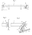
- eine schematische Schnittansicht durch einen Plattenboden eines Fahrzeuges mit geöffneter Spannvorrichtung und geöffneten Spannhaken;
- Fig. 2
- eine vergrößerte Ansicht der Spannvorrichtung analog Fig. 1;
- Fig. 3
- eine vergrößerte Ansicht eines Spannhakens in Offenstellung;
- Fig. 4
- eine Darstellung analog nach Fig. 1 mit geschlossener Spannvorrichtung;
- Fig. 5
- eine vergrößerte Darstellung der geschlossenen Spannvorrichtung nach Fig. 4;
- Fig.6
- eine vergrößerte Darstellung einer festgezurrten Plane mit geschlossenen Spannhaken.
- Fig. 1
- a schematic sectional view through a plate floor of a vehicle with an open tensioning device and open tensioning hook;
- Fig. 2
- an enlarged view of the clamping device analogous to FIG. 1;
- Fig. 3
- an enlarged view of a tensioning hook in the open position;
- Fig. 4
- a representation analogous to Figure 1 with a closed clamping device.
- Fig. 5
- an enlarged view of the closed clamping device according to Fig. 4;
- Figure 6
- an enlarged view of a lashed tarpaulin with closed hooks.
Gemäß den Fig. 1 bis 3 liegt eine Plane 1 vor, welche mit Spanngurten 2 und Ösen 4 versehen ist. Diese Plane 1 ist beispielsweise eine seitliche Schiebegardine an einem Fahrzeug, insbesondere einem Speditionsanhänger.1 to 3 is a tarpaulin 1, which with Tension belts 2 and eyelets 4 is provided. This tarpaulin 1 is for example a side curtain on a vehicle, especially a shipping trailer.
Das Fahrzeug weist einen Rahmen 7 auf, der mit einem Außenprofil
30 versehen ist. Im Profilraum des Außenprofils 30
befindet sich eine längsverlaufende Welle 6, an welcher Spannhaken
3 in bestimmten Abständen angeordnet sind. Die Welle 6
ist drehbar, und zwar mit Hilfe einer einzigen Spannvorrichtung
5.The vehicle has a
Fig. 3 zeigt die mit der drehbaren Welle 6 verbundenen Spannhaken
3 in Offenstellung. Fig. 2 zeigt, wie in dieser Lage die
Spannvorrichtung 5 positioniert ist. Diese Spannvorrichtung 5
ist als Doppelschwinge ausgebildet, wobei eine erste Schwinge
15 an der Welle 6 befestigt ist. Eine zweite Schwinge 16, die
mit einem Betätigungshebel 18 versehen ist, lagert in einer
Lagerstelle 17 unterhalb des Rahmens 7. Die beiden Schwingen
15 und 16 sind durch eine Koppel 20 miteinander verbunden.Fig. 3 shows the hooks connected to the
Die Koppel 20 ist längenveränderbar ausgebildet; sie weist bei
dem Ausführungsbeispiel eine Gewindehülse 21 mit zwei gegenläufigen
Gewindebolzen 22 und 23 auf. Hierdurch ist es möglich,
die Spannvorrichtung in funktionsgerechter Lage einzustellen.The
Der Betätigungshebel 18 ist mit einer Schließplatte 25 versehen,
welche in Schließstellung im Bereich einer anderen, an
der Lagerstellung 17 angeordneten Schließplatte 26 liegt.
Beide Schließplatten 25 und 26 können durch ein Schließelement
miteinander verriegelbar sein, so daß in Schließstellung die
Welle 6 nicht mehr drehbar ist. The actuating
In den Fig. 4, 5 und 6 ist die Schließstellung der erfindungsgemäßen
Vorrichtung dargestellt. Wie ersichtlich, wurde der
Betätigungshebel 8 im Uhrzeigersinn so lange gedreht, bis eine
Übertotpunktlage vorliegt, in welcher über die Koppel 20 und
die Schwinge 15 die Spannhaken 3 in Schließstellung liegen,
d.h. etwa horizontale Lage einnehmen. Nach Fig. 6 ist damit
die Plane 1 mit den Spanngurten 2 und den Ösen 4 sicher festgezurrt.
In dieser Position liegen die beiden Schließplatten
25 und 26 nach Fig. 5 aneinander und können durch ein nicht
näher dargestelltes Schließelement, beispielsweise einen Zollverschluß
oder ein herkömmliches Schloß, miteinander verschlossen
werden. Damit ist ein unbefugtes Öffnen über die
Spannvorrichtung 5 nicht mehr gegeben.4, 5 and 6 is the closed position of the invention
Device shown. As can be seen, the
Actuating lever 8 turned clockwise until one
Excess dead center position, in which via the
In Schließstellung liegen die beiden Schließplatten 25 und 26
an der Innenseite des Außenprofils 30 des Rahmens.In the closed position, the two locking
Da die mit den Spannhaken 3 versehene Welle 6 im Profilraum
des Außenprofils 30 gelagert ist, wird die Welle einwandfrei
vor Beschädigungen geschützt. Außerdem geht aus Fig. 1 und 4
hervor, daß sie außerhalb des Bereichs eines schematisch dargestellten
Reifens 28 liegt.Since the
Gemäß Fig. 6 sind die mit Ösen 4 versehenen Spanngurte 2 um
eine abgerundete Abschlußkante 31 des Außenprofils 30 des
Rahmens herumgeführt, so daß eine eventuelle Beschädigung beim
Schließvorgang vermieden wird.6, the lashing straps 2 provided with eyelets 4 are around
a
Aus den Figuren, insbesondere 2 und 5, geht hervor, daß das
Außenprofil 30 als Winkelprofil ausgebildet ist mit zwei profilierten,
unterschiedliche Breite aufweisenden Schenkeln 33
und 34. Der schmalere Schenkel 33 liegt vorteilhafterweise
horizontal, während der breitere Schenkel 34 vertikal längsseitig
des Fahrzeugs verläuft. Innerhalb des von den Schenkeln
33 und 34 umgrenzten Raums des Außenprofils 30 befindet sich
die längsverlaufende Welle 6.From the figures, in particular 2 and 5, it can be seen that the
Durch die erfindungsgemäße Verriegelungsvorrichtung ergibt
sich eine sog. Planenzentralverriegelung, welche nach Einhängen
der Ösen in die Spannhaken mit einem einzigen Arbeitsgang
ein Festzurren der Plane ermöglicht, wobei in Schließstellung
die gesamte Einheit abschließbar ist. Damit ist ein schnelles
Öffnen und Schließen der Spanngurte gewährleistet. Da diese
Spanngurte um das Außenprofil 30 herumgeführt sind, liegt eine
durchgehend gespannte Plane 1 vor, welche eine größere Werbefläche
bietet.Results from the locking device according to the invention
a so-called tarpaulin central locking, which after hanging
the eyelets into the tension hooks in a single operation
lashing down the tarpaulin allows, in the closed position
the entire unit is lockable. So that's a quick one
Guaranteed opening and closing of the tension belts. This one
Lashing straps are guided around the
Claims (11)
- Locking device for a tarpaulin (1), in particular for closing and bracing a lateral sliding curtain on a vehicle, in particular a haulage trailer, comprising tension straps (2) fastened to the tarpaulin (1), tension hooks (3) and at least one tensioning device (5) between the tension straps (2) and the tension hooks (3), wherein the tension hooks (3) are disposed on a common shaft (6), which is supported in the frame (7) of the vehicle and connected to the single tensioning device (5),
characterized in that the tensioning device (5) takes the form of a double rocker, wherein a first rocker (15) is fastened to the shaft (6), and a second rocker (16) provided with an operating lever (18) is supported at a bearing point (17) below the frame (7) and both rockers (15, 16) are connected to one another by a connecting rod (20). - Device according to claim 1,
characterized by
top dead centre position of the double rocker in closed position of the tensioning device (5). - Device according to claim 1,
characterized in that the tensioning device (5) is adjustable by means of the connecting rod (20), which is designed so as to be variable in length. - Device according to claim 3,
characterized in that the connecting rod (20) comprises a tapped bueh (21) with two oppositely threaded bolts (22, 23). - Device according to one of the preceding claims,
characterized in that the tensioning device (5) is lockable in closed position. - Device according to claim 5,
characterized in that the operating lever (18) is provided with a closing plate (25), which in closed position lies in
the region of another closing plate (26) disposed at the bearing point (17), and both closing plates (25, 26) are interlockable by means of a closing element. - Device according to claim 6,
characterized in that in closed position the two closing plates (25, 26) are disposed at the inside of an outer section (30) of the frame (7). - Device according to one or more of the preceding claims,
characterized in that the shaft (6) provided with the tension hooks (3) is supported in the section space of the outer section (30) of the frame (7). - Device according to claim 8,
characterized in that the tension hooks in closed position lie approximately horizontally and the tension straps (2) provided with eyes (4) are conveyed around a rounded-off end edge (31) of the outer section (30) of the frame (7) - Device according to one or more of the preceding claims,
characterized in that the outer section (30) takes the form of an angle section comprising two shaped limbs (33, 34) of differing width. - Device according to claim 10,
characterized in that the narrower limb (33) extends horizontally and the wider limb (34) extends vertically in longitudinal direction of the vehicle.
Applications Claiming Priority (2)
| Application Number | Priority Date | Filing Date | Title |
|---|---|---|---|
| DE29614478U DE29614478U1 (en) | 1996-08-21 | 1996-08-21 | Locking device for a tarpaulin |
| DE29614478U | 1996-08-21 |
Publications (2)
| Publication Number | Publication Date |
|---|---|
| EP0825049A1 EP0825049A1 (en) | 1998-02-25 |
| EP0825049B1 true EP0825049B1 (en) | 2002-05-15 |
Family
ID=8028122
Family Applications (1)
| Application Number | Title | Priority Date | Filing Date |
|---|---|---|---|
| EP97113555A Expired - Lifetime EP0825049B1 (en) | 1996-08-21 | 1997-08-06 | Locking device for tarpaulins |
Country Status (5)
| Country | Link |
|---|---|
| EP (1) | EP0825049B1 (en) |
| AT (1) | ATE217585T1 (en) |
| CZ (1) | CZ263997A3 (en) |
| DE (2) | DE29614478U1 (en) |
| HU (1) | HUP9701415A3 (en) |
Cited By (2)
| Publication number | Priority date | Publication date | Assignee | Title |
|---|---|---|---|---|
| DE102010045524A1 (en) | 2010-09-15 | 2012-03-15 | Kögel Trailer GmbH & Co. KG | Fastening device for a tarpaulin structure of a commercial vehicle, commercial vehicle body and commercial vehicle with such a fastening device |
| EP2556975A2 (en) | 2011-08-11 | 2013-02-13 | Kögel Trailer GmbH & Co. KG | Actuating device for closing and tensioning an awning and commercial vehicle with such an actuating device |
Families Citing this family (3)
| Publication number | Priority date | Publication date | Assignee | Title |
|---|---|---|---|---|
| US8303017B2 (en) * | 2006-07-14 | 2012-11-06 | Leblanc Sheri | Sidewall panel and tarpaulin cover system for flat bed trailers, and truck trailer incorporating same |
| DE102011052579B4 (en) | 2011-08-11 | 2018-07-26 | Kögel Trailer GmbH & Co. KG | Closure device for a tarpaulin of a commercial vehicle body and commercial vehicle body with such a closure device |
| DE102017126055A1 (en) * | 2017-11-08 | 2019-05-09 | Schmitz Cargobull Ag | Tarpaulin structure and tarpaulin unit for a commercial vehicle |
Family Cites Families (4)
| Publication number | Priority date | Publication date | Assignee | Title |
|---|---|---|---|---|
| CH605237A5 (en) * | 1975-11-20 | 1978-09-29 | Frech Hoch E Ag | Flexible side walls for lorry |
| FR2352689A1 (en) * | 1976-05-28 | 1977-12-23 | Laloyeau Carrosserie | Vehicle load cover sheet tensioning gear - uses sheet with straps on lower ledge tensioned by turning longitudinal shaft under load platform |
| FR2667552A1 (en) * | 1990-10-04 | 1992-04-10 | Walter Ets Lucien | Tarpaulin fitting/removal device for a transport vehicle |
| DE9206151U1 (en) * | 1992-05-07 | 1992-07-16 | Wihag Nutzfahrzeugtechnik Gmbh & Co Kg, 4800 Bielefeld, De |
-
1996
- 1996-08-21 DE DE29614478U patent/DE29614478U1/en not_active Expired - Lifetime
-
1997
- 1997-08-06 DE DE59707261T patent/DE59707261D1/en not_active Expired - Fee Related
- 1997-08-06 EP EP97113555A patent/EP0825049B1/en not_active Expired - Lifetime
- 1997-08-06 AT AT97113555T patent/ATE217585T1/en not_active IP Right Cessation
- 1997-08-19 CZ CZ972639A patent/CZ263997A3/en unknown
- 1997-08-19 HU HU9701415A patent/HUP9701415A3/en unknown
Cited By (5)
| Publication number | Priority date | Publication date | Assignee | Title |
|---|---|---|---|---|
| DE102010045524A1 (en) | 2010-09-15 | 2012-03-15 | Kögel Trailer GmbH & Co. KG | Fastening device for a tarpaulin structure of a commercial vehicle, commercial vehicle body and commercial vehicle with such a fastening device |
| EP2431205A2 (en) | 2010-09-15 | 2012-03-21 | Kögel Trailer GmbH & Co. KG | Mounting device for a canvas cover of a commercial vehicle, commercial vehicle structure and commercial vehicle with such a mounting device |
| EP2556975A2 (en) | 2011-08-11 | 2013-02-13 | Kögel Trailer GmbH & Co. KG | Actuating device for closing and tensioning an awning and commercial vehicle with such an actuating device |
| DE102011052581A1 (en) | 2011-08-11 | 2013-02-14 | Kögel Trailer GmbH & Co. KG | Actuating device for closing and tensioning a tarpaulin and commercial vehicle body with such an actuator |
| EP2556975A3 (en) * | 2011-08-11 | 2013-07-31 | Kögel Trailer GmbH & Co. KG | Actuating device for closing and tensioning an awning and commercial vehicle with such an actuating device |
Also Published As
| Publication number | Publication date |
|---|---|
| CZ263997A3 (en) | 1998-03-18 |
| HU9701415D0 (en) | 1997-10-28 |
| ATE217585T1 (en) | 2002-06-15 |
| DE59707261D1 (en) | 2002-06-20 |
| HUP9701415A2 (en) | 1999-07-28 |
| HUP9701415A3 (en) | 1999-12-28 |
| EP0825049A1 (en) | 1998-02-25 |
| DE29614478U1 (en) | 1996-10-24 |
Similar Documents
| Publication | Publication Date | Title |
|---|---|---|
| EP0925975B1 (en) | Body structure for commercial vehicle | |
| DE10292035B4 (en) | vehicle body | |
| DE202008008651U1 (en) | Commercial vehicle body and holding element for a commercial vehicle body | |
| AT409616B (en) | SLIDING SLIDING DOOR FOR A VEHICLE | |
| EP3178693B1 (en) | Device for securing loads on a load surface, in particular locking device transverse to the longitudinal direction of a load surface | |
| EP0825049B1 (en) | Locking device for tarpaulins | |
| EP3106333B1 (en) | Vehicle body, in particular for commercial vehicles, commercial vehicle with such a vehicle body and method of manufacturing | |
| EP0569039A2 (en) | Vehicle | |
| DE102013201005A1 (en) | Side roller carriage and guide belt with rail for a sliding roof structure of a vehicle body or a container | |
| DE3618420A1 (en) | Load-securing means on vehicle loading areas | |
| DE202015106725U1 (en) | Device for securing cargo | |
| EP3590761B1 (en) | Commercial vehicle structure | |
| DE1605315A1 (en) | Device for anchoring and securing vehicles on a transport vehicle | |
| EP0131706A2 (en) | Tensionable curtain awning | |
| DE112013000001T5 (en) | connecting means | |
| DE102019101047B4 (en) | Commercial vehicle body and commercial vehicle with such a commercial vehicle body | |
| EP2708393B1 (en) | Vehicle structure for the transport of bulk or stackable transport goods | |
| EP2431205B1 (en) | Mounting device for a canvas cover of a commercial vehicle, commercial vehicle structure and commercial vehicle with such a mounting device | |
| DE3425016C2 (en) | ||
| DE2233779C3 (en) | Stake arrangement for trucks and rail vehicles | |
| EP0164744B1 (en) | Device for detachably fixing a tarpaulin to a utility vehicle | |
| EP0858930A1 (en) | Tarpaulins with clamping device for lorries | |
| EP0825048B1 (en) | Anular fixation element | |
| DE2510493C3 (en) | Tension lock for holding a plank, in particular a side wall of a transport vehicle | |
| EP1375313A2 (en) | Motor vehicle |
Legal Events
| Date | Code | Title | Description |
|---|---|---|---|
| PUAI | Public reference made under article 153(3) epc to a published international application that has entered the european phase |
Free format text: ORIGINAL CODE: 0009012 |
|
| AK | Designated contracting states |
Kind code of ref document: A1 Designated state(s): AT BE CH DE DK IT LI NL |
|
| AX | Request for extension of the european patent |
Free format text: AL;LT;LV;RO;SI |
|
| 17P | Request for examination filed |
Effective date: 19980709 |
|
| AKX | Designation fees paid |
Free format text: AT BE CH DE DK IT LI NL |
|
| RBV | Designated contracting states (corrected) |
Designated state(s): AT BE CH DE DK IT LI NL |
|
| 17Q | First examination report despatched |
Effective date: 19991008 |
|
| GRAG | Despatch of communication of intention to grant |
Free format text: ORIGINAL CODE: EPIDOS AGRA |
|
| GRAG | Despatch of communication of intention to grant |
Free format text: ORIGINAL CODE: EPIDOS AGRA |
|
| GRAH | Despatch of communication of intention to grant a patent |
Free format text: ORIGINAL CODE: EPIDOS IGRA |
|
| GRAH | Despatch of communication of intention to grant a patent |
Free format text: ORIGINAL CODE: EPIDOS IGRA |
|
| GRAA | (expected) grant |
Free format text: ORIGINAL CODE: 0009210 |
|
| AK | Designated contracting states |
Kind code of ref document: B1 Designated state(s): AT BE CH DE DK IT LI NL |
|
| PG25 | Lapsed in a contracting state [announced via postgrant information from national office to epo] |
Ref country code: NL Free format text: LAPSE BECAUSE OF FAILURE TO SUBMIT A TRANSLATION OF THE DESCRIPTION OR TO PAY THE FEE WITHIN THE PRESCRIBED TIME-LIMIT Effective date: 20020515 Ref country code: IT Free format text: LAPSE BECAUSE OF FAILURE TO SUBMIT A TRANSLATION OF THE DESCRIPTION OR TO PAY THE FEE WITHIN THE PRESCRIBED TIME-LIMIT;WARNING: LAPSES OF ITALIAN PATENTS WITH EFFECTIVE DATE BEFORE 2007 MAY HAVE OCCURRED AT ANY TIME BEFORE 2007. THE CORRECT EFFECTIVE DATE MAY BE DIFFERENT FROM THE ONE RECORDED. Effective date: 20020515 |
|
| REF | Corresponds to: |
Ref document number: 217585 Country of ref document: AT Date of ref document: 20020615 Kind code of ref document: T |
|
| REG | Reference to a national code |
Ref country code: CH Ref legal event code: EP |
|
| REF | Corresponds to: |
Ref document number: 59707261 Country of ref document: DE Date of ref document: 20020620 |
|
| PG25 | Lapsed in a contracting state [announced via postgrant information from national office to epo] |
Ref country code: AT Free format text: LAPSE BECAUSE OF NON-PAYMENT OF DUE FEES Effective date: 20020806 |
|
| PG25 | Lapsed in a contracting state [announced via postgrant information from national office to epo] |
Ref country code: DK Free format text: LAPSE BECAUSE OF FAILURE TO SUBMIT A TRANSLATION OF THE DESCRIPTION OR TO PAY THE FEE WITHIN THE PRESCRIBED TIME-LIMIT Effective date: 20020815 |
|
| PG25 | Lapsed in a contracting state [announced via postgrant information from national office to epo] |
Ref country code: LI Free format text: LAPSE BECAUSE OF NON-PAYMENT OF DUE FEES Effective date: 20020831 Ref country code: CH Free format text: LAPSE BECAUSE OF NON-PAYMENT OF DUE FEES Effective date: 20020831 Ref country code: BE Free format text: LAPSE BECAUSE OF NON-PAYMENT OF DUE FEES Effective date: 20020831 |
|
| NLV1 | Nl: lapsed or annulled due to failure to fulfill the requirements of art. 29p and 29m of the patents act | ||
| BERE | Be: lapsed |
Owner name: *MBFL FLIEGL G.M.B.H. Effective date: 20020831 |
|
| PG25 | Lapsed in a contracting state [announced via postgrant information from national office to epo] |
Ref country code: DE Free format text: LAPSE BECAUSE OF NON-PAYMENT OF DUE FEES Effective date: 20030301 |
|
| PLBE | No opposition filed within time limit |
Free format text: ORIGINAL CODE: 0009261 |
|
| STAA | Information on the status of an ep patent application or granted ep patent |
Free format text: STATUS: NO OPPOSITION FILED WITHIN TIME LIMIT |
|
| REG | Reference to a national code |
Ref country code: CH Ref legal event code: PL |
|
| 26N | No opposition filed |
Effective date: 20030218 |