EP0824798B1 - Filtrage adaptatif a sous-bandes - Google Patents
Filtrage adaptatif a sous-bandes Download PDFInfo
- Publication number
- EP0824798B1 EP0824798B1 EP96919852A EP96919852A EP0824798B1 EP 0824798 B1 EP0824798 B1 EP 0824798B1 EP 96919852 A EP96919852 A EP 96919852A EP 96919852 A EP96919852 A EP 96919852A EP 0824798 B1 EP0824798 B1 EP 0824798B1
- Authority
- EP
- European Patent Office
- Prior art keywords
- sub
- band
- digital signal
- signal
- transmitted digital
- Prior art date
- Legal status (The legal status is an assumption and is not a legal conclusion. Google has not performed a legal analysis and makes no representation as to the accuracy of the status listed.)
- Expired - Lifetime
Links
- 230000003044 adaptive effect Effects 0.000 title claims description 66
- 238000001914 filtration Methods 0.000 title claims description 47
- 238000000034 method Methods 0.000 claims description 64
- 230000006978 adaptation Effects 0.000 claims description 51
- 238000012546 transfer Methods 0.000 claims description 17
- 238000005070 sampling Methods 0.000 claims description 16
- 230000005540 biological transmission Effects 0.000 claims description 11
- 230000004044 response Effects 0.000 claims description 2
- 230000015556 catabolic process Effects 0.000 claims 2
- 230000003111 delayed effect Effects 0.000 claims 1
- 230000001747 exhibiting effect Effects 0.000 claims 1
- 238000009434 installation Methods 0.000 claims 1
- 230000008569 process Effects 0.000 description 36
- 230000006870 function Effects 0.000 description 14
- 239000013598 vector Substances 0.000 description 9
- 239000011159 matrix material Substances 0.000 description 8
- 238000001228 spectrum Methods 0.000 description 7
- 238000004364 calculation method Methods 0.000 description 6
- 230000000875 corresponding effect Effects 0.000 description 6
- 238000012545 processing Methods 0.000 description 6
- 239000006185 dispersion Substances 0.000 description 5
- 238000000354 decomposition reaction Methods 0.000 description 4
- 238000010586 diagram Methods 0.000 description 4
- 235000021183 entrée Nutrition 0.000 description 4
- 230000009466 transformation Effects 0.000 description 4
- 238000005457 optimization Methods 0.000 description 3
- 241000135309 Processus Species 0.000 description 2
- 238000007792 addition Methods 0.000 description 2
- 230000021615 conjugation Effects 0.000 description 2
- 101150087426 Gnal gene Proteins 0.000 description 1
- 238000013459 approach Methods 0.000 description 1
- 230000008901 benefit Effects 0.000 description 1
- 230000008859 change Effects 0.000 description 1
- 238000004891 communication Methods 0.000 description 1
- 230000000052 comparative effect Effects 0.000 description 1
- 230000002596 correlated effect Effects 0.000 description 1
- 230000001934 delay Effects 0.000 description 1
- 230000000694 effects Effects 0.000 description 1
- 238000002474 experimental method Methods 0.000 description 1
- 238000009472 formulation Methods 0.000 description 1
- 230000014509 gene expression Effects 0.000 description 1
- 230000003993 interaction Effects 0.000 description 1
- 230000000873 masking effect Effects 0.000 description 1
- 239000000203 mixture Substances 0.000 description 1
- 230000004048 modification Effects 0.000 description 1
- 238000012986 modification Methods 0.000 description 1
- 230000009467 reduction Effects 0.000 description 1
- 230000002123 temporal effect Effects 0.000 description 1
- 238000000844 transformation Methods 0.000 description 1
- 230000017105 transposition Effects 0.000 description 1
Images


Classifications
-
- H—ELECTRICITY
- H03—ELECTRONIC CIRCUITRY
- H03H—IMPEDANCE NETWORKS, e.g. RESONANT CIRCUITS; RESONATORS
- H03H21/00—Adaptive networks
- H03H21/0012—Digital adaptive filters
- H03H21/0025—Particular filtering methods
- H03H21/0027—Particular filtering methods filtering in the frequency domain
-
- H—ELECTRICITY
- H04—ELECTRIC COMMUNICATION TECHNIQUE
- H04B—TRANSMISSION
- H04B3/00—Line transmission systems
- H04B3/02—Details
- H04B3/20—Reducing echo effects or singing; Opening or closing transmitting path; Conditioning for transmission in one direction or the other
- H04B3/21—Reducing echo effects or singing; Opening or closing transmitting path; Conditioning for transmission in one direction or the other using a set of bandfilters
Definitions
- the present invention relates to a method of adaptive filtering, by weighted optimization criteria, of a digital signal broken down into frequency sub-bands, and the corresponding filtering device.
- FIG. 1a An original digital signal, consisting of a succession of samples, is transmitted in the form of a digital signal transmitted succession of samples x n via any transmission channel 10, with the introduction of certain distortions. It is assumed, in such a case, that the distortions or deformations undergone by the original signal d n , during transmission, can be assimilated to a linear filtering.
- An equalizer device 11 makes it possible to model, adaptively, a filter whose transfer function is the inverse of that of the transmission channel 10, so that the signal y n delivered by the filter constituted by the equalizer device 11 is the as close as possible to the original signal d n . Under these conditions, the adaptation of the coefficients of the filter constituted by the equalizing device 11 makes it possible to minimize the energy of the modeling error, e n , equal to the difference between the original digital signal d n and the signal digital transmitted y n .
- the second application relates to the cancellation of acoustic echo and is shown schematically in Figure 1b.
- a first speaker being in room 20, speaks into a microphone 202 located in room 20, and receives a speech signal x n coming from a second remote speaker via a speaker 201 also located in room 20. It is assumed that room 20 acts on this received speech signal x n as a linear filter. Thus, the microphone 202 picks up a signal d n originating from the speech signal x n after filtering by the room 20. This signal d n is therefore sent back to the second remote speaker in the form of an echo of his own words.
- the filter constituted by the room In order to suppress this undesirable echo, we seek to model, by means of an echo canceller device 21, the filter constituted by the room, so that the signal y n delivered by the echo canceller device is the most possible close to the echo signal d n .
- the adaptive filtering process therefore involves implementation of filters with variable coefficients in the time. Variations for adaptation of the values of these coefficients are established thanks to an optimization criterion and performed according to a process or algorithm adaptation.
- the criterion of minimization of the mean square error associated with the gradient algorithm ( Least Mean Square algorithm, LMS in English term for algorithm least squares) is most often used, because of the good compromise that it offers between simplicity of implementation and efficiency of treatment.
- this processing mode has a relatively slow convergence speed, which constitutes a major drawback for many applications.
- modified versions of the LMS algorithm have been proposed.
- a first approach consisted, in order to reduce the computation complexity and to increase the speed of convergence of the adaptation algorithm, to carry out the adaptive filtering in frequency sub-bands.
- the corresponding operating mode consists in subdividing the input signal and the output signal of the system to be modeled into adjacent frequency sub-bands, to sub-sample each signal in sub-band, and to apply to this signal the filtering process adaptive.
- the purpose of the sub-sampling operation is to obtain a better calculation efficiency than in the case of a full band filtering process, and the processing in each sub-band can make it possible to improve the speed of convergence of the process. adaptation, due to the fact that it is possible to optimize the speed of convergence thereof in each of the sub-bands.
- A. GILLOIRE and M.VETTERLI have, in a publication entitled "Adaptive Filtering in Subbands with Critical Sampling: Analysis, Experiments, and Application to Acoustic Echo Cancellation", IEEE Transactions on Signal Processing, Vol.40, N ° 8, August 1992, describes an adaptive filtering algorithm in sub-bands, the essential object of which is a reduction in the computation complexity, an increase in the speed of convergence of the adaptation process which can, if necessary, be sought. .
- the proposed solution consists in postponing the adaptive filtering process into frequency sub-bands.
- document US-A-5 329 587 describes a succession of steps consisting in decomposing a reference signal and an error signal in sub-bands, and to generate weighting coefficients for each sub-band.
- weights are then transformed in the frequency domain, accumulated and re-transformed in the time domain to obtain coefficients of a programmable broadband filter.
- the reference signal is filtered using this wide filter band to generate an estimated disturbing signal, which is subtracted from the original signal, containing the signal disruptive, and thereby mitigate or remove the latter.
- a such a process appears complex due in particular to the process of retransformation of the accumulated coefficients in the time domain.
- An object of the present invention is the implementation work of an adaptive filtering method and device a digital signal broken down into frequency sub-bands, optimizing the speed of convergence of the adaptation process, without increasing complexity of calculation implemented.
- Another object of the present invention is further the implementation of a method and a device for adaptive filtering of a digital signal broken down into sub-bands frequencies, in which the optimization of the convergence speed is obtained by a weighted criterion minimum mean square error error of error signals in sub-band.
- Another object of the present invention is finally the implementation of a filtering method and device adaptive of a digital signal broken down into sub-bands of frequencies in which the folding phenomenon of spectrum can be obscured, thanks to the implementation of the adaptive filtering process in the time domain.
- this transmitted digital signal consisting of a succession of samples (x n ) representative of an original signal (d n ) submitted to a phenomenon of distortion after transmission via a transmission channel are remarkable in that they consist respectively of subjecting the transmitted digital signal (x n ) to an adaptive filtering of transfer function (W * ) to obtain a transmitted digital signal filtered succession of samples (y n ), generate an error signal (e n ) for each sample considered, algebraic difference between the original digital signal (d n ) and the transmitted digital signal filtered (y n ), subject the error signal (e n ) to a subdivision by orthogonal decomposition into a determined number (N) of frequency sub-bands of determined width, to generate rer, for each sub-band, a sub-band error signal, subjecting each sub-band error signal to decimation subsampling in a ratio (N) equal to the number of sub-bands, for obtain a set
- the adaptive filtering method and device objects of the invention find application to techniques equalization, as mentioned earlier in the description, as well as echo cancellation techniques, including speech signals.
- the variables considered will be assumed to be complex, which corresponds to the most general case.
- the operator (.) T designates the transposition operation
- the operator (.) * Designates the conjugation operation
- the operator (.) H the transconjugation operation ((.) T ) * in the classic sense of these terms in the signal processing technique.
- step 1000 a digital signal x n and the original signal d n as defined above in the context of one or other of the applications are considered.
- the method which is the subject of the present invention consists, in the following step 1001, in subjecting the signal x n to an adaptive filtering, y n designating the signal obtained after filtering.
- k is a positive integer designating the k th iteration of the adaptation process as illustrated in Figure 2.
- this error signal e n is subdivided into a determined number N of frequency sub-bands by means of an orthogonal decomposition by the implementation of the matrix of the coefficients H defined above.
- this decomposition is carried out by an orthogonal transformation implemented by a bank of analysis filters of a bank of filters with perfect reconstruction without loss, such as TFD (Transformed from Discrete Fourier) or TCD (Discrete Cosine) or ELT (for Extended Lapped Transform) or MLT (for Modulated Lapped Transform).
- the orthogonality of the transformation H followed by the sub-sampling ensures that the application of a minimization criterion on the mean square error once decomposed into sub-bands is equivalent to the application of the same criterion on the non error broken down, due to the lossless nature of the analysis filter bank.
- the subsampling operation can consist in retaining a sample value out of N samples, each group of N samples constituting a block of determined rank k for which an iteration of the adaptation process is carried out. There is thus obtained in each sub-band an undersampled error signal e ik .
- the vector relation is obtained:
- step 1003 of decomposing the error signal into sub-bands and of sub-sampling is followed by a step 1004 consisting in applying to the set of error signals in sub- sub-sampled band a specific weighting by positive real coefficients ⁇ i , i being between 0 and N-1.
- step 1004 weighted sub-sampled sub-band error signals ⁇ i .e ik are thus obtained.
- step 1005 the digital signal transmitted x n is also subjected to a subdivision into N sub-bands.
- Step 1006 then consists in carrying out the product of each component in conjugate sub-band of the digital signal transmitted and of the error signal in weighted sub-band corresponding ⁇ i .e i, k and in adding the set of components in sub-band, and to assign to the sum thus obtained an adaptation step ⁇ , which provides the desired adaptation function ⁇ W *, that is to say the modification to be made to the coefficients of the adaptive filter W *.
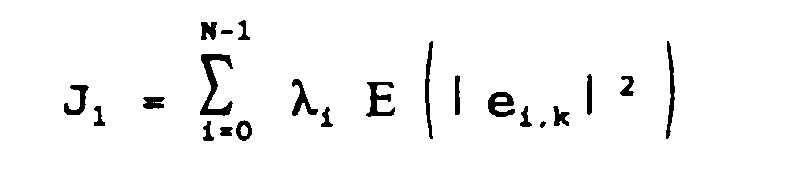
- the error criterion that the adaptive filtering process, object of the present invention, proposes to minimize is then of the form:
- the value of the adaptation function is modified consequently, which allows, by a step 1008 of incrementation of k, go to the next iteration.
- the value of the adaptation function and the transfer function adapted is maintained for the duration of N samples successive, subsampling period.
- FIG. 3a represents a first embodiment an adaptive filtering device implementing the process of the present invention, in the particular case where the number L of coefficients of the adaptive filter is less than or equal to the number N of sub-bands.
- the device represented in FIG. 3a comprises an adaptive filter 1, advantageously consisting of a transverse filter or temporal RIF (with Finite Impulse Response) of transfer function W * having a length L.
- an adder-subtractor module 2 making it possible to calculate the difference e n between the original signal d n and the signal y n , obtained from the digital signal transmitted x n by filtering in the adaptive filter 1
- the output of the adder-subtractor module 2 is connected to a bank 3 of N filters for analysis of respective transfer functions H 0 , H i , ..., H N-1 and each having KN coefficients.
- the bank 3 of filters making it possible to carry out the subdivision into N sub-bands of the error signal e n is advantageously constituted by the bank of analysis filters of a bank of filters with perfect reconstruction without loss, which guarantees the conservation, in the sub-bands, of all the information contained in the error signal e n .
- a module 3 ′ comprising a filter bank similar to the analysis filter bank 3 is provided, in order to carry out the subdivision into N sub-bands of the digital signal transmitted x n .
- the subdivision into sub-bands of the digital signal transmitted x n can be carried out either in parallel with the subdivision carried out using the analysis filter bank 3, or sequentially from the same filter bank 3, the filter bank of the module 3 'being eliminated.
- a sub-sampling module 4 is provided in a ratio N equal to the number of sub-bands.
- the sub-sampling module 4 can be, in a simplified embodiment, reduced to a routine for calculating a value on N successive samples in the context of a software implementation, or on the contrary formed from a selectively addressable memory as part of a physical implementation, in the form of a dedicated circuit.
- the sub-sampling module 4 is followed by a weighting module 5.
- the weighting module 5 can for example consist of a table of values, from which N weighting coefficients are chosen.
- each sub-sampled sub-band error signal e i, k can be associated a weighting coefficient ⁇ i , positive real, of determined value.
- the table of values can include various arbitrary values, these values being able to be updated with each iteration.
- Each coefficient ⁇ i can for example have a value approaching at each iteration the value of the average energy of the digital signal transmitted in sub-band x i, n and / or of the signal-to-noise ratio in each sub-band considered.
- the outputs of the analysis filter bank of the module 3 ′ advantageously include a conjugation module, C i , i ⁇ [0, N-1] allowing the components to be delivered directly under - conjugate band x i, n * of the digital signal transmitted.
- the outputs of the weighting module 5 as well as the outputs of the module 3 ' are supplied as input to a multiplier module 6, followed by a summing module 7.
- the multiplier module 6 can be constituted by a plurality of elementary multipliers P i , i ⁇ [0, N-1], and delivers the term-to-term product (Schur product) of weighted sub-sampled sub-band error signals and digital signals transmitted in sub-band.
- the summing module 7 receives all of the products term by term and delivers the adaptation function ⁇ W *.
- the adaptive filtering is carried out in sub-band.
- the device comprises a subdivision module into N 3 "sub-bands with which is associated a sub-sampling module 4", another sub-sampling module 4 "'being further associated with another subdivision module in 3 "subband.
- the 3 "and 4" modules allow the original signal d n to be sub-sampled into sub-bands respectively. The same applies to the modules 3 "'and 4"' relative to the digital signal transmitted x n .
- the subtractor adder module 2 is replaced by a module 2 ′ comprising a plurality of subtractor adder modules AD i .
- An adaptive filter module 1 ' is provided, which receives the sub-sampled sub-band components of the transmitted digital signal and delivers the sub-band components of the filtered digital transmitted signal y i, k to the subtractor adder module 2'. The latter delivers the sub-sampled subband error signals e ik to the weighting module 5.
- the elements 1, 2, 3, 3 ', 4, 5 are the same as in the mode of Figure 3a; their description is therefore not redone.
- Steps 1006 and 1007 are identical but can be carried out by memorizing at step 1005 calculation results already obtained for the M-1 blocks of samples prior to the current block of samples, as follows.
- each sub-band component of the transmitted digital signal is multiplied with the component of the weighted sub-sampled sub-error error signal corresponding to ⁇ i .e i, k .
- the products thus obtained are added while being processed in the form of M packets of N coefficients, which is achieved by successively delaying by N samples the conjugate sub-band components x in * of the digital signal transmitted, delivered by the 3 'module previously described.
- these delays are produced by means of M delay modules 8 0 , ..., 8 M-1 each comprising N delay elements each assigned to a sub-band.
- the multiplier module 6 of FIG. 3 is here reproduced M times, at 6 0 ..., 6 M-1 .
- the summing module 7 of FIG. 3 is likewise reproduced M times, at 7 0 , ..., 7 M-1 .
- the main advantage of the process which is the subject of the present invention lies in the weighting by the coefficients ⁇ i . Indeed, a judicious choice of these coefficients makes it possible to make the speed of convergence of the algorithm optimal in each frequency sub-band.
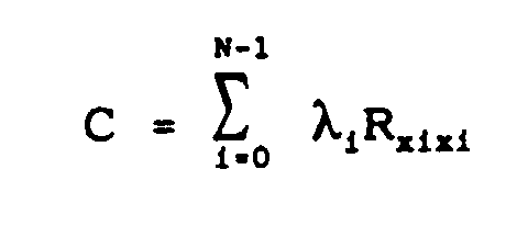
- the decomposition in sub-bands is related to the eigenvalues of the convergence matrix of the adaptive filter, which is defined by: where R xixi is the auto-correlation matrix of size L of the signals x i, n of output of the 1 st filter H i of the analysis bench.
- R xixi is the auto-correlation matrix of size L of the signals x i, n of output of the 1 st filter H i of the analysis bench.
- the speed of convergence is determined by the dispersion of the eigenvalues of the convergence matrix C, defined as the ratio of the largest to the smallest eigenvalue. The closer this dispersion is to 1, that is to say the closer the eigenvalues are to each other, the faster the convergence. It is well known that for a conventional LMS algorithm, the optimal convergence speed is obtained when the adaptation step is proportional to the inverse of the energy of the input signal.
- the adaptation process minimizes the error in each sub-band substantially independently, and these errors can be adjusted with a different adaptation step. In this sense, the adaptation process of the present invention behaves like several LMS algorithms implemented substantially separately in each sub-band.
- the curves of FIG. 5 also make it possible to compare the speed of convergence of the adaptation process object of the present invention to that of a conventional LMS algorithm.
- the input signal of the adaptive filter is a so-called USASI noise (stationary noise having on average the same spectrum as speech), a white Gaussian noise b n having been superimposed on the original signal d n , the signal to noise ratio d n / b n being 40 dB.
- the curve in solid lines represents the decrease in the mean square error for the adaptation process which is the subject of the present invention, while that in mixed lines relates to a conventional LMS algorithm.
- Process Multiplications Additions LMS 6146 10240 WSAF 1013.38 3,725.38
- the conforming adaptation process to the subject of the filtering process and device according to the invention allows a simplification of the calculation complexity and an increase in the speed of convergence, no approximation from the point of view of adaptive filtering should not be introduced in order to put implement the adaptation process in each sub-band and therefore the overall adaptation process.
Landscapes
- Engineering & Computer Science (AREA)
- Computer Networks & Wireless Communication (AREA)
- Signal Processing (AREA)
- Filters That Use Time-Delay Elements (AREA)
Description
A titre d'exemple non limitatif, on considérera deux applications fondamentales des techniques du filtrage adaptatif.
La première application relative à la technique d'égalisation adaptative est représentée de façon schématique en figure 1a. Un signal numérique d'origine, constitué par une succession d'échantillons, est transmis sous forme d'un signal numérique transmis succession d'échantillons xn par l'intermédiaire d'un canal de transmission 10 quelconque, avec introduction de certaines distorsions. On suppose, dans un tel cas, que les distorsions ou déformations subies par le signal d'origine dn, lors de la transmission, peuvent être assimilées à un filtrage linéaire. Un dispositif égaliseur 11 permet de modéliser, de manière adaptative, un filtre dont la fonction de transfert est l'inverse de celle du canal de transmission 10, de façon que le signal yn délivré par le filtre constitué par le dispositif égaliseur 11 soit le plus proche possible du signal d'origine dn. Dans ces conditions, l'adaptation des coefficients du filtre constitué par le dispositif égaliseur 11 permet de rendre minimale l'énergie de l'erreur de modélisation, en, égale à la différence entre le signal numérique d'origine dn et le signal numérique transmis yn.
La deuxième application se rapporte à l'annulation d'écho acoustique et est représentée de façon schématique en figure 1b. Dans le cas d'une situation de communication téléphonique de type "mains libres", un premier locuteur, se trouvant dans une salle 20, parle dans un microphone 202 situé dans la salle 20, et reçoit un signal de parole xn provenant d'un deuxième locuteur à distance par l'intermédiaire d'un haut-parleur 201 également situé dans la salle 20. On suppose que la salle 20 agit sur ce signal de parole reçu xn comme un filtre linéaire. Ainsi, le microphone 202 capte un signal dn issu du signal de parole xn après filtrage par la salle 20. Ce signal dn est donc renvoyé au deuxième locuteur à distance sous forme d'un écho à ses propres paroles. Afin de supprimer cet écho indésirable, on cherche à modéliser, au moyen d'un dispositif annuleur d'écho 21, le filtre constitué par la salle, de façon que le signal yn délivré par le dispositif annuleur d'écho 21 soit le plus proche possible du signal d'écho dn. De même que dans la première application, l'adaptation des coefficients du filtre constitué par le dispositif annuleur d'écho 21 permet de rendre l'énergie de l'erreur de modélisation, en = dn-yn, minimale.
En particulier, une première approche a consisté, afin de réduire la complexité de calcul et d'augmenter la vitesse de convergence de l'algorithme d'adaptation, à réaliser le filtrage adaptatif en sous-bandes de fréquences. Le mode opératoire correspondant consiste à subdiviser le signal d'entrée et le signal de sortie du système à modéliser en sous-bandes de fréquences adjacentes, à sous-échantillonner chaque signal en sous-bande, et à appliquer à ce signal le processus de filtrage adaptatif. L'opération de sous-échantillonnage a pour objet d'obtenir une meilleure efficacité de calcul que dans le cas d'un processus de filtrage pleine bande, et le traitement dans chaque sous-bande peut permettre d'améliorer la vitesse de convergence du processus d'adaptation, en raison du fait qu'il est possible d'optimiser la vitesse de convergence de celui-ci dans chacune des sous-bandes.
La solution proposée consiste à reporter le processus de filtrage adaptatif en sous-bandes de fréquences.
Toutefois, afin de permettre la mise en oeuvre d'une solution exacte, il est nécessaire d'effectuer en outre un filtrage inter-bande en raison de l'existence d'une intercorrélation entre les spectres de fréquence de chacune des sous-bandes constituées. Ainsi, pour une subdivision en N sous-bandes, il est nécessaire de mettre en oeuvre N2 filtres, de longueur N fois plus faible, ce qui ne réduit donc aucunement le volume de calcul global. En outre, en raison de l'intercorrélation précitée entre les spectres de fréquence de chacune des sous-bandes, les coefficients de filtrage des filtres utilisés sont liés et le filtrage adaptatif lui-même est très difficile à mettre en oeuvre.
- la figure 2 représente, sous forme illustrative, un organigramme de l'ensemble des étapes de mise en oeuvre du procédé de filtrage adaptatif d'un signal numérique objet de la présente invention ;
- la figure 3a représente, sous forme de schéma fonctionnel, un mode particulier de réalisation non limitatif d'un dispositif de filtrage adaptatif conforme à l'objet de la présente invention, dans le cas où, dans un but de simplification, le nombre de coefficients du filtre adaptatif mis en oeuvre est inférieur ou égal au nombre de sous-bandes de fréquences ;
- la figure 3b représente, sous forme de schéma fonctionnel, une variante de réalisation du dispositif de la figure 3a dans lequel le filtre adaptatif est implanté en sous-bandes ;
- la figure 4 représente, dans le cas général, sous forme de schéma fonctionnel, un mode particulier de réalisation non limitatif d'un dispositif de filtrage adaptatif conforme à l'objet de la présente invention, dans le cas où le nombre de coefficients du fltre adaptatif est un multiple entier du nombre de sous-bandes de fréquences ;
- la figure 5 représente un graphe illustrant un exemple de décroissance dans le temps de l'erreur de modélisation d'un canal de transmission dans le cas de la mise en oeuvre d'un processus d'adaptation LMS classique et d'un processus d'adaptation conforme à l'objet de la présente invention respectivement.
- n =
- rang de chaque échantillon de tout signal numérique entrant dans la mise en oeuvre du procédé et du dispositif selon l'invention ;
- N =
- nombre de sous-bandes dans lequel la subdivision en sous-bandes est réalisée ;
- Wn =
- (w0, w1 ..., wj, ..., wL-1)t
fonction de transfert du filtre adaptatif pour l'échantillon de rang n, wj désignant le coefficient de rang j du filtre adaptatif, L la longueur en nombre de coefficients du filtre adaptatif ; - Xn =
- (xn, xn-1, ..., xn-KN+1)t
vecteur d'entrée du signal numérique transmis comportant KN composantes constituées par un bloc de KN échantillons successifs, K désignant un entier supérieur ou égal à 1 ; - χn =
- (Xn, Xn-1, ..., Xn-L+1)KNxL
matrice d'entrée de dimension KNxL, constituée par L vecteurs d'entrée du signal numérique transmis successifs ; - Dn =
- (dn, dn-1, ..., dn-KN+1)t
vecteur d'entrée du signal numérique d'origine comportant KN composantes constituées par un bloc de KN échantillons successifs ; - En =
- (en, en-1, ..., en-KN+1)t
vecteur d'erreur comportant KN composantes ; - H =
- (H0 t, ..., Hi t, ..., HN-1 t)t
matrice des coefficients de l'opérateur de subdivision en N sous-bandes, Hi t représentant un vecteur de KN coefficients associé à la sous-bande de rang i.
L'opération de sous-échantillonnage peut consister à retenir une valeur d'échantillon sur N échantillons, chaque groupe de N échantillons constituant un bloc de rang k déterminé pour lequel une itération du processus d'adaptation est effectuée. On obtient ainsi dans chaque sous-bande un signal d'erreur sous-échantillonné ei.k. On obtient, à l'issue de l'étape 1003, la relation vectorielle :




En prenant pour chaque sous-bande de rang i considéré :

En outre, ainsi que représenté en figure 3a, les sorties du banc de filtres d'analyse du module 3' comportent avantageusement un module de conjugaison, Ci, i ∈ [0,N-1] permettant de délivrer directement les composantes en sous-bande conjuguées xi,n* du signal numérique transmis. Les sorties du module 5 de pondération ainsi que les sorties du module 3' sont fournies en entrée à un module multiplicateur 6, suivi d'un module sommateur 7. Le module multiplicateur 6 peut être constitué par une pluralité de multiplicateurs élémentaires Pi, i ∈ [0,N-1], et délivre le produit terme à terme (produit de Schur) des signaux d'erreur en sous-bande sous-échantillonnés pondérés et des signaux numériques transmis en sous-bande.
Le module sommateur 7 reçoit l'ensemble des produits terme à terme et délivre la fonction d'adaptation ΔW*.
En outre, le dispositif comprend un module de subdivision en N sous-bandes 3" auquel est associé un module de sous-échantillonnage 4", un autre module de sous-échantillonnage 4"' étant en outre associé à un autre module de subdivision en sous-bande 3"'. Les modules 3" et 4" permettent de subdiviser en sous-bande respectivement de sous-échantillonner le signal d'origine dn. Il en est de même en ce qui concerne les modules 3"' et 4"' relativement au signal numérique transmis xn. Le module additionneur soustracteur 2 est remplacé par un module 2' comportant une pluralité de modules additionneurs soustracteurs ADi. Un module de filtrage adaptatif 1' est prévu, lequel reçoit les composantes en sous-bande sous-échantillonnées du signal numérique transmis et délivre les composantes en sous-bande du signal numérique transmis filtré yi,k au module additionneur soustracteur 2'. Ce dernier délivre les signaux d'erreur en sous-bande sous-échantillonnés ei.k au module de pondération 5.
Un tableau comparatif ci-après indique le nombre de multiplications et d'additions de nombres réels nécessaires par échantillon de signal numérique transmis xn pour un algorithme LMS classique respectivement dans le cas d'un processus d'adaptation conforme au procédé objet de la présente invention, désigné par WSAF, mis en oeuvre dans le cas d'une transformation ELT K=2, pour L=1024, N-32 pour un même signal numérique transmis xn.
| Processus | Multiplications | Additions |
| LMS | 6146 | 10240 |
| WSAF | 1013,38 | 3725,38 |
Claims (10)
- Procédé de filtrage adaptatif d'un signal numérique transmis, constitué par une succession d'échantillons (xn), cette succession d'échantillons (xn) étant représentative d'un signal d'origine (dn) soumis à un phénomène de distorsion après transmission par l'intermédiaire d'un canal de transmission, ledit procédé de filtrage comprenant les étapes consistant à soumettre ledit signal numérique transmis (xn) à un filtrage adaptatif de fonction de transfert (W*) pour obtenir un signal numérique transmis filtré succession d'échantillons (Yn), engendrer un signal d'erreur (en) pour chaque échantillon considéré, différence algébrique entre le signal numérique d'origine (dn) et le signal numérique transmis filtré (yn), caractérisé en ce qu'il consiste à :soumettre ledit signal d'erreur (en) à une subdivision par décomposition orthogonale en un nombre déterminé (N) de sous-bandes de fréquences de largeur déterminée, pour engendrer, pour chaque sous-bande, un signal d'erreur en sous-bande ;à soumettre chaque signal d'erreur en sous-bande à un sous-échantillonnage par décimation dans un rapport (N), égal au nombre de sous-bandes, pour obtenir un ensemble de signaux d'erreur en sous-bande sous-échantillonnés (ei,k), où i désigne le rang de la sous-bande considérée, i ∈ [0,N-1], k désignant le rang d'un bloc de N échantillons ;soumettre l'ensemble des signaux d'erreur en sous-bande (ei.k) sous-échantillonnés à une pondération spécifique de coefficient (λi) pour engendrer des signaux d'erreur en sous-bande pondérés sous-échantillonnés (λi.ei,k), λi désignant un réel positif, à l'exclusion de λi=1 ∀ i ;soumettre en outre ledit signal numérique transmis (xn) à une subdivision en un même nombre déterminé de (N) sous-bandes pour engendrer une pluralité de composantes en sous-bande (xi.n) de signal numérique transmis ;établir une fonction d'adaptation (ΔW*) de la fonction de transfert (W*) du filtre adaptatif comme la somme du produit de chaque composante en sous-bande conjuguée du signal numérique transmis et du signal d'erreur en sous-bande sous-échantillonné pondéré correspondant (λi.ei,k) affectée d'un pas d'adaptation (µ), ce qui permet pour un critère global d'erreur minimale, énergie minimale des signaux d'erreur en sous-bande sous-échantillonnés pondérés, d'optimiser indépendamment la vitesse de convergence du filtre adaptatif dans chaque sous-bande et ainsi la vitesse de convergence globale du filtre adaptatif.
- Procédé selon la revendication 1, caractérisé en ce que chaque coefficient de pondération (λi) est pris égal à une valeur déterminée, ce qui permet d'amener la vitesse de convergence dudit filtre adaptatif à une même valeur optimale pour chaque sous-bande de rang i considéré.
- Procédé selon l'une quelconque des revendications 1 ou 2, caractérisé en ce que pour un filtre adaptatif de fonction de transfert (W*) comportant un nombre (L) de coefficients inférieur ou égal au nombre (N) de sous-bandes, la fonction d'adaptation (ΔW*) de la fonction de transfert (W*) dudit filtre adaptatif est égale à un incrément algébrique de chaque coefficient du filtre adaptatif de fonction de transfert (W*).
- Procédé selon l'une quelconque des revendications 1 ou 2, caractérisé en ce que pour un filtre adaptatif de fonction de transfert (W*) comportant un nombre (L) de coefficients multiple du nombre (N) de sous-bandes, celui-ci consiste en outre à retarder successivement les composantes en sous-bande (xi.n) du signal numérique transmis de (N) échantillons, ce qui permet d'engendrer des valeurs de fonction d'adaptation à partir de valeurs retardées correspondant à (M) paquets de (N) coefficients, avec M = L/N.
- Procédé selon la revendication 4, caractérisé en ce que chaque coefficient (λi) relatif à la sous-bande de rang i est pris proportionnel à l'inverse de l'estimée d'énergie de la composante en sous-bande du signal numérique transmis (xi,n) dans la sous-bande de fréquence de rang i.
- Dispositif de filtrage adaptatif d'un signal numérique transmis, constitué par une succession d'échantillons (xn), cette succession d'échantillons (xn) étant représentative d'un signal d'origine (dn) soumis à un phénomène de distorsion après transmission par l'intermédiaire d'un canal de transmission, comprenant au moins :des moyens (1) de filtrage adaptatif du signal numérique transmis (xn), présentant une fonction de transfert (W*) et permettant d'obtenir un signal numérique transmis filtré succession d'échantillons (yn) ;des moyens (2) générateurs d'un signal d'erreur (en) pour chaque échantillon considéré, différence algébrique entre le signal numérique d'origine (dn) et le signal numérique transmis filtré (yn), caractérisé en ce qu'il comprend :des moyens (3, 3') de subdivision en sous-bandes du signal d'erreur (en) par décomposition orthogonale et du signal numérique transmis (xn) en un nombre déterminé (N) de sous-bandes de largeur déterminée, pour engendrer pour chaque sous-bande, un signal d'erreur en sous-bande et un signal numérique transmis en sous-bande (xi,n) où i désigne le rang de la sous-bande considérée, i ∈ [0,N-1] ;des moyens (4) de sous-échantillonnage de chaque signal d'erreur en sous-bande par décimation dans un rapport (N) égal au nombre de sous-bandes, lesdits moyens de sous-échantillonnage (4) permettant d'obtenir un ensemble de signaux d'erreur en sous-bande sous-échantillonnés (ei,k), k désignant le rang d'un bloc de N échantillons ;des moyens (5) de pondération à partir d'un coefficient de pondération (λi) desdits signaux d'erreur en sous-bande sous-échantillonnés (ei,k) permettant d'engendrer des signaux d'erreur en sous-bande sous-échantillonnés pondérés (λi.ei,k), λi désignant un réel positif, à l'exclusion de λi = 1 ∀ i ;des moyens générateurs (6,7) d'une fonction d'adaptation (ΔW*) de la fonction de transfert (W*) dudit filtre adaptatif, ladite fonction d'adaptation étant établie comme la somme du produit de chaque composante en sous-bande du signal numérique transmis et du signal d'erreur en sous-bande sous-échantillonné pondéré correspondant (λi.ei,k) affectée d'un pas d'adaptation (µ), ce qui permet pour un critère global d'erreur minimale, énergie minimale desdits signaux d'erreur en sous-bande sous-échantillonnés pondérés, d'optimiser indépendamment la vitesse de convergence du filtre adaptatif dans chaque sous-bande et ainsi la vitesse de convergence globale du filtre adaptatif.
- Dispositif selon la revendication 6, caractérisé en ce que lesdits moyens (1) de filtrage adaptatif sont constitués par toute implantation d'un filtre RIF temporel de longueur L déterminée, en pleine bande ou en sous-bande.
- Dispositif selon l'une des revendications 6 ou 7, caractérisé en ce que lesdits moyens (3, 3') sont constitués par un banc de filtres à reconstruction parfaite sans perte, ce banc de filtres comprenant un banc de filtres d'analyse et un banc de filtres de reconstruction, ledit banc de filtres d'analyse recevant ledit signal d'erreur (en) respectivement ledit signal numérique transmis (xn) et délivrant lesdits signaux d'erreur en sous-bande respectivement lesdits signaux numériques transmis en sous-bande (xi,n).
- Dispositif selon l'une des revendications 6 à 8, caractérisé en ce que lesdits moyens (5) de pondération sont constitués par un module de pondération comprenant (N) coefficients de pondération (λi), à chaque signal d'erreur en sous-bande sous-échantillonné (ei.k) étant associé un coefficient de pondération (λi), réel positif, de rang i correspondant et de valeur déterminée, chaque coefficient de pondération (λi) étant fonction de l'énergie du signal dans la sous-bande de rang i et du rapport signal à bruit dans la sous-bande de rang i correspondant.
- Dispositif selon l'une des revendications 6 à 9, caractérisé en ce que lesdits moyens générateurs (6, 7) d'une fonction d'adaptation (ΔW*) de la fonction de transfert (W*) dudit filtre adaptatif comprennent au moins :un module multiplicateur (6) permettant d'effectuer un produit terme à terme des signaux d'erreur en sous-bande sous-échantillonnés pondérés et des signaux numériques transmis en sous-bande, et délivrant un ensemble de produits terme à terme correspondant ;un module sommateur (7) recevant ledit ensemble de produits terme à terme et délivrant ladite fonction d'adaptation.
Applications Claiming Priority (3)
| Application Number | Priority Date | Filing Date | Title |
|---|---|---|---|
| FR9505410A FR2733866B1 (fr) | 1995-05-05 | 1995-05-05 | Procede de filtrage adaptatif, par critere d'optimisation pondere d'un signal numerique decompose en sous-bandes de frequences et dispositif correspondant |
| FR9505410 | 1995-05-05 | ||
| PCT/FR1996/000664 WO1996035266A1 (fr) | 1995-05-05 | 1996-05-02 | Filtrage adaptatif a sous-bandes |
Publications (2)
| Publication Number | Publication Date |
|---|---|
| EP0824798A1 EP0824798A1 (fr) | 1998-02-25 |
| EP0824798B1 true EP0824798B1 (fr) | 1999-06-09 |
Family
ID=9478749
Family Applications (1)
| Application Number | Title | Priority Date | Filing Date |
|---|---|---|---|
| EP96919852A Expired - Lifetime EP0824798B1 (fr) | 1995-05-05 | 1996-05-02 | Filtrage adaptatif a sous-bandes |
Country Status (4)
| Country | Link |
|---|---|
| EP (1) | EP0824798B1 (fr) |
| DE (1) | DE69602838T2 (fr) |
| FR (1) | FR2733866B1 (fr) |
| WO (1) | WO1996035266A1 (fr) |
Family Cites Families (1)
| Publication number | Priority date | Publication date | Assignee | Title |
|---|---|---|---|---|
| US5329587A (en) * | 1993-03-12 | 1994-07-12 | At&T Bell Laboratories | Low-delay subband adaptive filter |
-
1995
- 1995-05-05 FR FR9505410A patent/FR2733866B1/fr not_active Expired - Fee Related
-
1996
- 1996-05-02 EP EP96919852A patent/EP0824798B1/fr not_active Expired - Lifetime
- 1996-05-02 DE DE69602838T patent/DE69602838T2/de not_active Expired - Fee Related
- 1996-05-02 WO PCT/FR1996/000664 patent/WO1996035266A1/fr not_active Ceased
Also Published As
| Publication number | Publication date |
|---|---|
| DE69602838T2 (de) | 1999-12-23 |
| WO1996035266A1 (fr) | 1996-11-07 |
| FR2733866B1 (fr) | 1997-07-18 |
| DE69602838D1 (de) | 1999-07-15 |
| EP0824798A1 (fr) | 1998-02-25 |
| FR2733866A1 (fr) | 1996-11-08 |
Similar Documents
| Publication | Publication Date | Title |
|---|---|---|
| EP0748555B1 (fr) | Annuleur d'echo acoustique avec filtrage en sous-bandes | |
| EP0932964B1 (fr) | Procede et dispositif d'egalisation aveugle des effets d'un canal de transmission sur un signal de parole numerique | |
| EP0710947B1 (fr) | Procédé et dispositif de suppression de bruit dans un signal de parole, et système avec annulation d'écho correspondant | |
| EP0333581B1 (fr) | Dispositif annuleur d'écho à filtrage en sous-bandes de fréquence | |
| CN1223166C (zh) | 在回波消除系统中用于改进子频带自适应滤波的方法和装置 | |
| EP1438870A1 (fr) | Methode et systeme d'elimination d'interference pour antenne multicapteur | |
| FR2789823A1 (fr) | Filtres a sous-bandes unilaterales | |
| WO1998047276A1 (fr) | Procede d'annulation d'echo acoustique multi-voies et annuleur d'echo acoustique multi-voies | |
| EP0692883B1 (fr) | Procédé d'égalisation aveugle et son application à la reconnaissance de la parole | |
| FR2554996A1 (fr) | Procede et dispositif pour la determination de la position optimale du coefficient de reference d'un egaliseur adaptatif | |
| JPH10164686A (ja) | 最適小波パケットおよび交差周波数帯消去を用いた副周波数帯反響消去装置 | |
| EP0884926B1 (fr) | Procédé et dispositif de traitement optimisé d'un signal perturbateur lors d'une prise de son | |
| FR2808391A1 (fr) | Systeme de reception pour antenne multicapteur | |
| EP0848866B1 (fr) | Dispositif de filtrage avec retour de decision, dans le domaine frequentiel | |
| EP1103138B1 (fr) | Dispositif de traitement numerique a filtrage frequentiel et a complexite de calcul reduite | |
| EP0585434B1 (fr) | Procede et dispositif de filtrage pour la reduction des preechos d'un signal audio-numerique | |
| EP0824798A1 (fr) | Filtrage adaptatif a sous-bandes | |
| JP2000134138A (ja) | 副帯エコ―を打ち消すための無遅延システム | |
| EP1155497B1 (fr) | Procede et systeme de traitement de signaux d'antenne | |
| EP2078301A1 (fr) | Reduction de bruit et de distorsion dans une structure de type forward | |
| EP0848867A1 (fr) | Procede de filtrage numerique adaptatif dans le domaine frequentiel | |
| WO2021198587A1 (fr) | Procédé de contrôle de retour acoustique avec filtrage adaptatif | |
| WO2011091928A1 (fr) | Procede de reduction de longueur de canal, filtre et signal correspondants |
Legal Events
| Date | Code | Title | Description |
|---|---|---|---|
| PUAI | Public reference made under article 153(3) epc to a published international application that has entered the european phase |
Free format text: ORIGINAL CODE: 0009012 |
|
| 17P | Request for examination filed |
Effective date: 19971027 |
|
| AK | Designated contracting states |
Kind code of ref document: A1 Designated state(s): DE GB IT |
|
| 17Q | First examination report despatched |
Effective date: 19980406 |
|
| GRAG | Despatch of communication of intention to grant |
Free format text: ORIGINAL CODE: EPIDOS AGRA |
|
| GRAG | Despatch of communication of intention to grant |
Free format text: ORIGINAL CODE: EPIDOS AGRA |
|
| GRAH | Despatch of communication of intention to grant a patent |
Free format text: ORIGINAL CODE: EPIDOS IGRA |
|
| GRAH | Despatch of communication of intention to grant a patent |
Free format text: ORIGINAL CODE: EPIDOS IGRA |
|
| GRAA | (expected) grant |
Free format text: ORIGINAL CODE: 0009210 |
|
| AK | Designated contracting states |
Kind code of ref document: B1 Designated state(s): DE GB IT |
|
| PG25 | Lapsed in a contracting state [announced via postgrant information from national office to epo] |
Ref country code: IT Free format text: LAPSE BECAUSE OF FAILURE TO SUBMIT A TRANSLATION OF THE DESCRIPTION OR TO PAY THE FEE WITHIN THE PRE;WARNING: LAPSES OF ITALIAN PATENTS WITH EFFECTIVE DATE BEFORE 2007 MAY HAVE OCCURRED AT ANY TIME BEFORE 2007. THE CORRECT EFFECTIVE DATE MAY BE DIFFERENT FROM THE ONE RECORDED.SCRIBED TIME-LIMIT Effective date: 19990609 |
|
| REF | Corresponds to: |
Ref document number: 69602838 Country of ref document: DE Date of ref document: 19990715 |
|
| GBT | Gb: translation of ep patent filed (gb section 77(6)(a)/1977) |
Effective date: 19990901 |
|
| PLBE | No opposition filed within time limit |
Free format text: ORIGINAL CODE: 0009261 |
|
| STAA | Information on the status of an ep patent application or granted ep patent |
Free format text: STATUS: NO OPPOSITION FILED WITHIN TIME LIMIT |
|
| 26N | No opposition filed | ||
| REG | Reference to a national code |
Ref country code: GB Ref legal event code: IF02 |
|
| PGFP | Annual fee paid to national office [announced via postgrant information from national office to epo] |
Ref country code: DE Payment date: 20070426 Year of fee payment: 12 |
|
| PGFP | Annual fee paid to national office [announced via postgrant information from national office to epo] |
Ref country code: GB Payment date: 20070427 Year of fee payment: 12 |
|
| GBPC | Gb: european patent ceased through non-payment of renewal fee |
Effective date: 20080502 |
|
| PG25 | Lapsed in a contracting state [announced via postgrant information from national office to epo] |
Ref country code: DE Free format text: LAPSE BECAUSE OF NON-PAYMENT OF DUE FEES Effective date: 20081202 |
|
| PG25 | Lapsed in a contracting state [announced via postgrant information from national office to epo] |
Ref country code: GB Free format text: LAPSE BECAUSE OF NON-PAYMENT OF DUE FEES Effective date: 20080502 |