EP0823963B1 - Pump with tool-less pump head configuration - Google Patents
Pump with tool-less pump head configuration Download PDFInfo
- Publication number
- EP0823963B1 EP0823963B1 EP97907831A EP97907831A EP0823963B1 EP 0823963 B1 EP0823963 B1 EP 0823963B1 EP 97907831 A EP97907831 A EP 97907831A EP 97907831 A EP97907831 A EP 97907831A EP 0823963 B1 EP0823963 B1 EP 0823963B1
- Authority
- EP
- European Patent Office
- Prior art keywords
- plunger
- pump
- manifold
- pump head
- release mechanism
- Prior art date
- Legal status (The legal status is an assumption and is not a legal conclusion. Google has not performed a legal analysis and makes no representation as to the accuracy of the status listed.)
- Expired - Lifetime
Links
- 230000007246 mechanism Effects 0.000 claims description 32
- 239000012530 fluid Substances 0.000 claims description 6
- 229910052594 sapphire Inorganic materials 0.000 claims description 6
- 239000010980 sapphire Substances 0.000 claims description 6
- 238000007789 sealing Methods 0.000 claims description 6
- 230000000694 effects Effects 0.000 claims description 4
- 230000013011 mating Effects 0.000 claims description 2
- 230000006835 compression Effects 0.000 description 8
- 238000007906 compression Methods 0.000 description 8
- 238000009434 installation Methods 0.000 description 3
- 239000007788 liquid Substances 0.000 description 3
- 238000012423 maintenance Methods 0.000 description 3
- 229910001369 Brass Inorganic materials 0.000 description 2
- 229910000906 Bronze Inorganic materials 0.000 description 2
- 239000010951 brass Substances 0.000 description 2
- 239000010974 bronze Substances 0.000 description 2
- KUNSUQLRTQLHQQ-UHFFFAOYSA-N copper tin Chemical compound [Cu].[Sn] KUNSUQLRTQLHQQ-UHFFFAOYSA-N 0.000 description 2
- 238000004811 liquid chromatography Methods 0.000 description 2
- 238000000034 method Methods 0.000 description 2
- 230000000717 retained effect Effects 0.000 description 2
- 238000011109 contamination Methods 0.000 description 1
- 230000001419 dependent effect Effects 0.000 description 1
- 230000009977 dual effect Effects 0.000 description 1
- 230000008030 elimination Effects 0.000 description 1
- 238000003379 elimination reaction Methods 0.000 description 1
- 238000011010 flushing procedure Methods 0.000 description 1
- 238000009987 spinning Methods 0.000 description 1
Images
Classifications
-
- F—MECHANICAL ENGINEERING; LIGHTING; HEATING; WEAPONS; BLASTING
- F04—POSITIVE - DISPLACEMENT MACHINES FOR LIQUIDS; PUMPS FOR LIQUIDS OR ELASTIC FLUIDS
- F04B—POSITIVE-DISPLACEMENT MACHINES FOR LIQUIDS; PUMPS
- F04B53/00—Component parts, details or accessories not provided for in, or of interest apart from, groups F04B1/00 - F04B23/00 or F04B39/00 - F04B47/00
- F04B53/14—Pistons, piston-rods or piston-rod connections
-
- F—MECHANICAL ENGINEERING; LIGHTING; HEATING; WEAPONS; BLASTING
- F04—POSITIVE - DISPLACEMENT MACHINES FOR LIQUIDS; PUMPS FOR LIQUIDS OR ELASTIC FLUIDS
- F04B—POSITIVE-DISPLACEMENT MACHINES FOR LIQUIDS; PUMPS
- F04B53/00—Component parts, details or accessories not provided for in, or of interest apart from, groups F04B1/00 - F04B23/00 or F04B39/00 - F04B47/00
- F04B53/14—Pistons, piston-rods or piston-rod connections
- F04B53/144—Adaptation of piston-rods
- F04B53/147—Mounting or detaching of piston rod
-
- F—MECHANICAL ENGINEERING; LIGHTING; HEATING; WEAPONS; BLASTING
- F04—POSITIVE - DISPLACEMENT MACHINES FOR LIQUIDS; PUMPS FOR LIQUIDS OR ELASTIC FLUIDS
- F04B—POSITIVE-DISPLACEMENT MACHINES FOR LIQUIDS; PUMPS
- F04B53/00—Component parts, details or accessories not provided for in, or of interest apart from, groups F04B1/00 - F04B23/00 or F04B39/00 - F04B47/00
- F04B53/22—Arrangements for enabling ready assembly or disassembly
-
- F—MECHANICAL ENGINEERING; LIGHTING; HEATING; WEAPONS; BLASTING
- F05—INDEXING SCHEMES RELATING TO ENGINES OR PUMPS IN VARIOUS SUBCLASSES OF CLASSES F01-F04
- F05C—INDEXING SCHEME RELATING TO MATERIALS, MATERIAL PROPERTIES OR MATERIAL CHARACTERISTICS FOR MACHINES, ENGINES OR PUMPS OTHER THAN NON-POSITIVE-DISPLACEMENT MACHINES OR ENGINES
- F05C2201/00—Metals
- F05C2201/04—Heavy metals
- F05C2201/0469—Other heavy metals
- F05C2201/0475—Copper or alloys thereof
- F05C2201/0478—Bronze (Cu/Sn alloy)
-
- F—MECHANICAL ENGINEERING; LIGHTING; HEATING; WEAPONS; BLASTING
- F05—INDEXING SCHEMES RELATING TO ENGINES OR PUMPS IN VARIOUS SUBCLASSES OF CLASSES F01-F04
- F05C—INDEXING SCHEME RELATING TO MATERIALS, MATERIAL PROPERTIES OR MATERIAL CHARACTERISTICS FOR MACHINES, ENGINES OR PUMPS OTHER THAN NON-POSITIVE-DISPLACEMENT MACHINES OR ENGINES
- F05C2203/00—Non-metallic inorganic materials
- F05C2203/08—Ceramics; Oxides
- F05C2203/0865—Oxide ceramics
- F05C2203/0869—Aluminium oxide
- F05C2203/0873—Sapphire
Definitions
- the present invention relates to pumps, and more particularly to pumps used to deliver fluid at high pressure.
- Known pumps which deliver fluid at high pressure for use in applications such as liquid chromatography.
- Known pumps such as one disclosed in U.S. Patent No. 4,883,409 (“the '409 patent”) incorporate at least one plunger or piston which is reciprocated within a pump chamber into which fluid is introduced.
- the plunger is typically a delicate sapphire piston precisely machined to dimensions accommodated by the pump chamber. Frequency and stroke length of the plunger reciprocating within the pump chamber is controllable to control the flow rate of fluid output from the pump.
- the assembly for driving the plunger is an elaborate combination of elements that can introduce undesirable motion in the plunger as it is driven.
- Typical pumps known for delivery of liquids in liquid chromatography applications are dual piston pumps having two interconnected pump heads each with a reciprocating plunger.
- the plungers are driven with a predetermined phase difference in order to minimize output flow variations, such as disclosed in the '409 patent and further in U.S. Patent No. 4,681,513.
- the operator servicing the pump has to unbolt the pump head, which requires one tool, and unbolt a pump head support bushing, which requires yet another tool. Removal of the plunger via manipulation of the compression spring and snap ring requires two additional tools which must be manipulated simultaneously. To remove the plunger, the compression spring has to be compressed to a point at which the snap ring can be collapsed and removed. During any or all of the servicing steps, the operator has to be very careful not to break the exposed fragile sapphire plunger.
- the present invention aims at providing a pump configured so that tools are not required to remove the pump head and disassemble the plunger.
- a single large hand operated knob or head nut holds the pump head on and facilitates tool-less pump head removal.
- the pump head is guided into position in a manifold and held in place by the hand knob.
- the manifold is designed to receive all the external fluidic connections made to the pump head. Fluid paths to the pump head have been replaced with miniature face seals which facilitate high pressure sealing between the pump head and manifold when the two components are held against each other.
- Low pressure tubing seals reside in aseal wash housing which is housed in the manifold and are not attached to the head. No tools are required to disconnect the tubing during pump head removal.
- tool-less plunger removal is facilitated by a mechanism including a nutcap assembly having a bronze or brass plunger socket disposed at an end thereof.
- the plunger socket receives a plunger assembly including a sapphire plunger fixed to a plunger holder ball accommodated by the socket.
- the plunger assembly is captured within the socket by a plurality of cams engaging and permitting only limited pivotal motion of the plunger holder ball within the socket.
- the cams are constantly loaded by a spring to rotate and collapse onto the plunger holder ball, pulling the plunger assembly tightly into the socket to eliminate backlash between the plunger assembly and the nutcap assembly.
- the plunger protrudes outwardly from the plunger socket into the pump chamber through a plurality of seals and a restricting cone that facilitates tool-less removal of the plunger assembly and pump head assembly from the pump back-end.
- the single large hand knob which is sized to provide an ergonomic means of applying mechanical holding force required to hold the head in position and compress miniature face seals.
- the single hand knob eliminates the possible cocking that two bolts used in the prior art may introduce.
- Fluidic connections in the form of high pressure compression fittings and low pressure tubing connections to the pump head, which are typical in prior art pumps, have beenremoved from the pump design according to the invention and therefore high pressure fluidic connections do not need to be disconnected in removing the pump head.
- check valves do not need to be disturbed when removing the pump head. Fittings to the check valves, that had to be removed in prior art pumps, can remain in the valve eliminating the possibility of contamination entering into the check valve.
- the design of the pump according to the invention eliminates the need to remove a snap ring which retains a compression spring. This allows the plunger to be removed by simply manually unbolting the head nut knob to free the pump head, manually removing the seal wash tubes, manually positioning the restricting or release cone, and then driving the plunger forward under motor/computer control. Accordingly, the head and plunger assembly are withdrawn without requiring tools. Total elimination of tools required to remove the pump head and plunger is effected, and the risk of breaking the sapphire plunger during removal is substantially reduced. The time involved to change a seal or change a plunger is also substantially reduced.
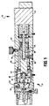
- a pump according to the invention illustrated in Fig. 1, has a motor end 10 and a pump head end 12. At the motor end, a motor 14 is configured, in this illustrative embodiment, to drive a ball-screw assembly 16 as known in the art.
- the ball-screw assembly includes a screw portion 18 rotated by the motor to linearly actuate a nut portion 20.
- a nut cap assembly 22 is disposed on the nut portion 20 and extends through a bushing 24 toward the pump head end 12 of the pump.
- Mechanisms to retain a plunger assembly 26 are disposed at an end of the nut cap assembly 22 distal to the nut portion 20 of the ball-screw assembly.
- the mechanics of the pump assembly substantially as described hereinafter, are housed in a mechanics housing 27.
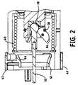
- a plunger socket 28, best illustrated in Figs. 1 and 2 is formed of bronze or brass and configured to receive the plunger assembly 26.
- the plunger assembly includes a sapphire plunger 30 fixed to a plunger holder ball 32 that is accommodated by the socket 28.
- the plunger holder ball 32 is captured within the socket 28 by a plurality of cams 34 engaging and permitting limited pivotal motion of the plunger holder ball 32 within the socket.
- the cams 34 in this illustrative embodiment three cams, are distributed substantially equidistantly about the circumference of the nutcap 22 and are constantly loaded by a garter-type spring 38.
- the spring 38 forces the cams 34 to rotate, with a portion of the cams rotating inwardly and collapsing onto the plunger holder ball 32 pushing it tightly into the socket 28 capturing the plunger assembly 26 to eliminate backlash between the plunger assembly and the nutcap assembly.
- a compression spring 40 which does not need to be removed to remove either the pump head or the plunger assembly, is incorporated in this illustrative design to eliminate backlash between the nutcap, thrust bearing and other drive components.
- the engaged plunger assembly 26 is driven into a release or restricting cone 42, manually or by operation of the motor 14.
- the cone is moved into the normal travel path of the mechanism to allow the cams to engage the cone.
- the restricting cone 42 has an inclined inner surface 44 which engages a surface of the cams 34 and rotates the cams away from the plunger holder ball 32 to release it. Engaging the surface of the cams against the inclined surface 44 of the restricting cone 42 automatically releases the plunger, not requiring an operator to have to manually disassemble the pump to remove the plunger. This avoids possible damage to the pump and saves a considerable amount of time.
- the cams 34 are designed in such a way that, while the cams hold the plunger holder ball 32 into the socket with considerable force, the force required to release the cams is much lower. This is achieved through mechanical advantage.
- the ball of the plunger assembly has a fixed radius while the surface of the cam has a gradually increasing radius.
- the garter spring (Fig. 2, 38) rotates the cam about its pivot point the increasing radius of the cam jams against the ball of the plunger assembly.
- the surface of the cam which contacts the ball on the plunger assembly has a low angle of contact with respect to the force from the garter spring.
- the same low angle mechanical advantage is used by the restricting cone 42 for releasing the ball on the plunger assembly.
- the cams contact the cone's inclined inner surface 44 on a side causing the cam to rotate away from the ball of the plunger holder thus allowing release.
- the restricting cone 42 is configured to be manually moved into position by the operator, thus not requiring additional strokes of the pump mechanics to actuate the plunger for release of the plunger assembly.
- the restricting cone is a unitary molded part that consists of two concentric rings.
- An inner ring 43 has the inclined surface 44 that contacts the cams.
- An outer ring 45 is external to the pump housing and is accessible to an operator.
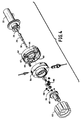
- the two rings 43, 45 are connected by a plurality of equidistantly distributed spokes 47 (best seen in Fig. 4).
- the spokes 47 pass through L-shaped slots (not shown) in the mechanics housing 27 that allow an engaged position at the baseof the "L" and a disengaged position at the top of the "L".
- the operator does not have to remove a manifold 54, described hereinafter, which receives fluidic connections and is configured so that the plunger can fit through a clearance hole in the manifold 54.
- the plunger is then accessible from the pump head end 12 of the pump to be simply pulled out of the socket 28 while the cams 34 have released the ball 32.
- the manifold 54 is disposed adjacent to the plunger release cone 42.
- the manifold 54 is configured to accept all the fluidic connections that in prior art pumps typically are made directly to the pump head.
- the manifold 54 is also configured to receive a seal wash housing 50, and various seals including fluidic face seals 56 which facilitate high pressure sealing between the pump head 48 and manifold 54 when the two components are held against each other.
- the seal wash housing 50 configured to be disposed within the manifold, facilitates flushing of the plunger at the back of a high pressure plunger seal 55 to wash away particulates that may form thereat.
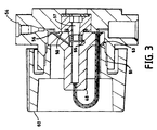
- the seal wash housing 50 provides a wash chamber 57 (best seen in Fig. 3), for liquid to collect and wash the plunger clean of particulate that may form due to imperfections in the high pressure seals.
- Low pressure seals e.g. wash plunger seal, wash tube seal and wash face seal, are used to contain the liquid in the seal wash chamber.
- Low pressure tubing seals 58 reside in the wash chamber 50 interior to the manifold 54 and are not attached to the head.
- the low pressure tubing seals 58 are designed to accept the tubing directly, not requiring compression fittings and thus eliminating the need for tooling to disconnect them during pump head removal.
- the low pressure tubing seals 58 used in this illustrative implementation are of the radial or radial-cup seal type which are configured for use in sealing shafts that are reciprocating or spinning.
- the seals include an internal spring which effects compression on the installed tubing. Forces exerted outwardly by the internal spring cause an expansion that effects a seal between the tubing and the seal wash housing 50.
- the manifold 54 retains the seal wash housing 50 and receives the tubing and high pressure fittings so that the pump head 48 itself does not have to be extensively manipulated, or have things disconnected from it or reconnected to it, to remove it and replace it in the pump.
- the pump head 48 is seated in the manifold 54 and is retained therein by a head nut or a single, large hand operated knob or nut 60.
- the head nut 60 in this illustrative embodiment is threaded into the manifold 54, as illustrated in Fig. 3.
- the nut 60 has an interior portion including male threads that screw into an engagement portion including mating female threads on an interior surface 51 of the manifold 54.
- a front face 53 of the nut 60 contacts the pump head assembly 48 effectively clamping the head 48 to the manifold 54.
- Simple removal of the head nut 60 releases the pump head 48 for removal.
- the single, large head nut 60 or hand knob is sized to provide an ergonomic means of applying the mechanical holding force required to hold the pump head 48 in position and compress the face seals 56.
- the single knob or nut 60 eliminates the possible cocking that two bolts used in the prior art may introduce.
- the operator removes wash tubes connected to the seal wash housing in the manifold as discussed hereinbefore. This operation, again, does not require any tools.
- the operator then manually removes the head nut 60.
- the release cone 42 is then manually actuated into position by the operator grasping the outer ring or portion 45 and moving the release cone 42 back engaging the spokes thereof in the base of the L-shaped slots.
- the plunger assembly is then actuated outwardly by the motor as directed by the operator, to engage the cams against the inclined surface of the release cone and release the plunger holder ball.
- the plunger assembly 30 can be removed by the operator along with the seal wash chamber or housing 50 and the pump head 48, minimizing the risk of broken plungers (and dropped or lost parts). Again, no tools are required.
- the manifold 54 remains attached to the mechanics housing 27, with the release cone 42 captured therebetween.
- the delicate plunger is protected during this tool-less disassembly process by the fact that it is allowed to remain in the pump head during the removal process.
- the pump head 48 is removed with the plunger retained in the head by seal friction. Once the head is removed, the plunger and head can be manually separated without constraint (prior art mechanisms required the removal of the pump head with the plunger still rigidly attached to the pump which caused damage to the plunger if the head was cocked or jarred during removal).
- Another significant advantage, among others, of the pump according to the invention, is that because the plunger assembly 26 does not have to be installed before installing the pump head 48, the plunger assembly 26 can be inserted into a plunger seal 52 already installed in the pump head 48 in a visible and controlled fashion, thus virtually eliminating the possibility of damage to the plunger seal during installation. This also allows the operator to assemble any plunger bearings and seal wash parts in a vertical manner minimizing dropped and or lost parts.
- the illustrative embodiment described herein includes a plunger holder "ball” and “socket” interfacing the plunger to the actuator/motor, it will be appreciated that mechanics other than a ball and socket could be implemented to releasably interface the plunger to the actuator, e.g. the ball could be a square or rectangular geometry or the like, while the socket could be a corresponding seating mechanism configured to receive the base of the plunger holder.
- cams 34 can be manipulated or actuated by a mechanism other than an inclined surface, such as by a tab or ridge or the like that effects actuation of the cams.
- a large hand knob or head nut 60 is described herein in the illustrative embodiment according to the invention, it will be appreciated that a wing or butterfly nut or other manually manipulable means for applying mechanical force to retain the pump head in the manifold could be implemented, such as bayonet type devices, clamps or the like.
- the manifold is described as having female threads for engaging corresponding male threads on the head nut, it will be appreciated that the thread configuration could be reversed, or alternative manually effected mechanical interconnection can beimplemented.
- the head nut herein is integral to the pump head end when installed, in alternative embodiments a removable knob or manually actuatable tool that need only be present for assembly and disassembly can be implemented.
- plunger assembly holding mechanism includes three cams, it will be appreciated that greater or fewer cams can be implemented in a design according to the invention. Additionally, alternative holding mechanisms, such as a ball and detente or other quick release mechanisms can be implemented.
- low pressure tubing seals in the illustrative embodiment described herein are radial-cup seals it will be appreciated that other configurations can be implemented for low pressure tubing interconnections that can be manually effected, such as other friction fittings, manually actuatable clamps or the like.
Landscapes
- Engineering & Computer Science (AREA)
- Mechanical Engineering (AREA)
- General Engineering & Computer Science (AREA)
- Details Of Reciprocating Pumps (AREA)
- Reciprocating Pumps (AREA)
Description
Claims (11)
- A pump having a motor end (10) and a pump head end (12) and a mechanics housing disposed therebetween, said pump head end (12) having a pump head (48) removably disposed therein, comprising:wherein said pump head (48) is releasable from said manifold (54) and removable from said pump head end (12) of said pump when said single nut or knob (60) is manually disengaged and removed from said manifold (54).a manifold (54) configured to receive fluidic connections to said pump, said manifold (54) having a first end proximate to said mechanics housing and a second end including an engagement portion (51), said second end being configured to receive said pump head (48) therein, anda single hand operated nut or knob (60), said nut or knob (60) having an interior portion releasably engagable and mating with said engagement portion (51) of said manifold (54) such that a mechanical force is applied via at least one interior surface (53) of said interior portion abutting said pump head (48) to clamp said pump head (48) to said manifold (54) to retain said pump head (48) within said manifold (54) when said interior portion is engaged with said engagement portion (51) of said manifold (54),
- The pump of claim 1 further including at least one face seal (56) disposed between said manifold (54) and said pump head (48) to effect sealing therebetween.
- The pump of claim 1 or 2 further including a seal wash housing (50) disposed within said manifold (54) to receive fluidic connections, said seal wash housing (50) being configured to receive seals (58) sealing said fluidic connections at said seal wash housing (50).
- The pump of claim 3 wherein at least some of said fluidic connections are low pressure connections and said seal wash housing (50) is configured to receive low pressure seals (58), said low pressure seals including radial-cup seals.
- The pump of claim 1, 2, 3 or 4 comprising:an actuator portion driven by a plunger (30) that is removable from said pump and adapted to deliver pressurized fluid via reciprocation thereof;a plunger assembly (26) including a plunger interface (32) attached to said plunger (30);a plunger socket (28) driven by said actuator portion and configured to receive said plunger interface (32);at least one holding mechanism (34) proximate to said plunger socket (28) and configured to releasably engage said plunger interface (32) to retain it in said plunger socket (28); anda release mechanism (42-45) accessible from exterior to said pump and configured to be actuatable between a first position and a second position, said release mechanism (42-45) being clear of said at least one holding mechanism (34) when said plunger (30) is reciprocating and said release mechanism (42-45) is in said first position, and said release mechanism (42-45) including a surface (44) that is engagable by said at least one holding mechanism (34) to release said plunger interface (32) when said release mechanism (42-45) is in said second position, wherein said plunger (30) is removable from said pump by actuating said release mechanism (42-45) to said second position and by actuating said actuator portion into a position whereat said at least one holding mechanism (34) engages said surface (44) of said release mechanism (42-45) to release said plunger interface (32) whereupon said plunger interface (32) is removable from said plunger socket (28).
- The pump of claim 5 wherein said actuator portion includes a ball-screw assembly (16) having a screw portion (18) and a nut portion (20) with a nutcap (22) disposed proximate to and being actuatable by said nut portion (20) as said nut portion (20) is driven along said screw portion (18), and wherein said plunger socket (28) is disposed at an end of said nutcap (22).
- The pump of claim 5 or 6 wherein said plunger comprises a sapphire rod (30).
- The pump of claim 5, 6 or 7 wherein said release mechanism comprises an exterior ring (45) accessible from exterior to said pump connected to an interior ring (43), said interior ring (43) includes said surface (44) in the form of an inclined interior surface (44), said exterior ring (45) being graspable by an operator to actuate said release mechanism between said first position and said second position, said inclined interior surface (44) being engaged by said at least one holding mechanism (34) to release said plunger interface (32) when said release mechanism is in said second position and when said actuator portion is moved into a position whereat said at least one holding mechanism (34) engages said inclined interior surface (44) of said release mechanism to release said plunger interface (32) whereupon said plunger interface (32) is removable from said plunger socket (28).
- The pump of claim 5, 6, 7 or 8 wherein said at least holding cam mechanism comprises a plurality of cams (34) disposed proximate to said plunger socket (28) and a garter-type spring (38) biasing said plurality of cams (34) into engagement with said plunger interface (32) to retain it in said plunger socket (28).
- The pump of claim 5, 6, 7, 8 or 9 wherein said plunger interface attached to said plunger (30) comprises a plunger holder ball (32) and said plunger socket (28) driven by said actuator portion is configured to receive said plunger holder ball (32).
- The pump of claim 5, 6, 7, 8, 9 or 10 wherein said release mechanism (42-45) has a release mechanism interior clearance permitting said plunger assembly (26) to pass therethrough, said manifold (54) is arranged adjacent said release mechanism (42-45), said manifold (54) having a manifold interior clearance permitting said plunger assembly (26) to pass therethrough, and said said plunger (30) is frictionally engaged within said pump head (48) and said pump head (48) is removable from said pump head end (12) of said pump with said plunger (30) frictionally engaged therein.
Priority Applications (1)
| Application Number | Priority Date | Filing Date | Title |
|---|---|---|---|
| EP02006718A EP1225336B1 (en) | 1996-02-23 | 1997-02-21 | Pump with tool-less pump head configuration |
Applications Claiming Priority (3)
| Application Number | Priority Date | Filing Date | Title |
|---|---|---|---|
| US606149 | 1996-02-23 | ||
| US08/606,149 US5788465A (en) | 1996-02-23 | 1996-02-23 | Tool-less pump head configuration |
| PCT/US1997/002900 WO1997031191A1 (en) | 1996-02-23 | 1997-02-21 | Readily disassembled pump head and plunger configuration |
Related Child Applications (1)
| Application Number | Title | Priority Date | Filing Date |
|---|---|---|---|
| EP02006718.7 Division-Into | 2002-03-22 |
Publications (2)
| Publication Number | Publication Date |
|---|---|
| EP0823963A1 EP0823963A1 (en) | 1998-02-18 |
| EP0823963B1 true EP0823963B1 (en) | 2003-08-13 |
Family
ID=24426769
Family Applications (2)
| Application Number | Title | Priority Date | Filing Date |
|---|---|---|---|
| EP02006718A Expired - Lifetime EP1225336B1 (en) | 1996-02-23 | 1997-02-21 | Pump with tool-less pump head configuration |
| EP97907831A Expired - Lifetime EP0823963B1 (en) | 1996-02-23 | 1997-02-21 | Pump with tool-less pump head configuration |
Family Applications Before (1)
| Application Number | Title | Priority Date | Filing Date |
|---|---|---|---|
| EP02006718A Expired - Lifetime EP1225336B1 (en) | 1996-02-23 | 1997-02-21 | Pump with tool-less pump head configuration |
Country Status (6)
| Country | Link |
|---|---|
| US (1) | US5788465A (en) |
| EP (2) | EP1225336B1 (en) |
| JP (1) | JP4033491B2 (en) |
| AU (1) | AU1972897A (en) |
| DE (2) | DE69725905T2 (en) |
| WO (1) | WO1997031191A1 (en) |
Families Citing this family (18)
| Publication number | Priority date | Publication date | Assignee | Title |
|---|---|---|---|---|
| US6736049B2 (en) * | 2000-12-11 | 2004-05-18 | Gilson, Inc. | High pressure low volume pump |
| DK1213479T3 (en) * | 2000-12-11 | 2003-07-07 | Gilson Inc | Low pressure high pressure pump |
| US20050254972A1 (en) * | 2004-05-14 | 2005-11-17 | Baker Rodney W | Bench top pump |
| US8960071B2 (en) | 2004-08-18 | 2015-02-24 | Waters Technologies Corporation | Piston pump with leak diagnostic port |
| JP5244388B2 (en) * | 2004-08-18 | 2013-07-24 | ウオーターズ・テクノロジーズ・コーポレイシヨン | Apparatus and method for generating or carrying fluid under pressure and seal member used in the apparatus |
| FR2904065A1 (en) * | 2006-07-18 | 2008-01-25 | Pulssar Technologies Sarl | Pumping unit for e.g. rinsing liquid substance sample, has guiding and connection module connecting pumping module and actuation module, and cylinder-spherical joint and cylindrical groove assembled to assure coupling between rod and piston |
| FR2904066B1 (en) * | 2006-07-18 | 2012-08-24 | Pulssar Technologies | PUMPING UNIT WITH HIGH LIFETIME. |
| US8337175B2 (en) * | 2009-12-22 | 2012-12-25 | Smith & Nephew, Inc. | Disposable pumping system and coupler |
| US8430651B2 (en) * | 2010-01-08 | 2013-04-30 | Medtronic, Inc. | Multi-material single-piece actuator member for miniature reciprocating piston pump in medical applications |
| CH703354A1 (en) * | 2010-06-21 | 2011-12-30 | Fives Cryomec Ag | Drive unit for a reciprocating pump. |
| JP2014508940A (en) * | 2011-03-10 | 2014-04-10 | ウオーターズ・テクノロジーズ・コーポレイシヨン | Pump head outlet port |
| CN103403412B (en) | 2011-03-10 | 2016-08-24 | 沃特世科技公司 | Seal assemblies for reciprocating and rotating applications |
| GB2490148B (en) * | 2011-04-20 | 2017-12-20 | Agilent Technologies Inc | Metering device with cartridge design to safely change metering head |
| GB2523571B (en) | 2014-02-27 | 2020-07-08 | Agilent Technologies Inc | Piston assembly interlocked with piston actuator being unlockable upon disassembly of pump |
| US20180073502A1 (en) * | 2016-09-09 | 2018-03-15 | Bio-Chem Fluidics, Inc. | Reciprocating piston pump and method of manufacture |
| DK3379084T3 (en) * | 2017-03-23 | 2020-03-16 | Xylem Europe Gmbh | Unlocking device for a hydraulic pump |
| CN112483381A (en) * | 2020-11-19 | 2021-03-12 | 江苏同济分析仪器有限公司 | Plunger mechanism of high-pressure infusion pump of liquid chromatograph |
| CN115163441B (en) * | 2022-08-04 | 2023-08-04 | 安徽工程大学 | A Plunger Variable Hydraulic Pump Based on Permanent Magnet Drive |
Family Cites Families (10)
| Publication number | Priority date | Publication date | Assignee | Title |
|---|---|---|---|---|
| US3697197A (en) * | 1970-08-06 | 1972-10-10 | Waterous Co | Ice cream pump |
| US3981620A (en) * | 1972-03-06 | 1976-09-21 | Waters Associates, Inc. | Pumping apparatus |
| US3880053A (en) * | 1974-05-31 | 1975-04-29 | Tl Systems Corp | Pump |
| US4173437A (en) * | 1977-08-01 | 1979-11-06 | The Perkin-Elmer Corporation | Dual-piston reciprocating pump assembly |
| US4281687A (en) * | 1979-02-09 | 1981-08-04 | Waters Associates, Inc. | Fluid storage device |
| GB2104607A (en) * | 1981-08-21 | 1983-03-09 | Wilkinson Sword Ltd | Hose couplings |
| US4723941A (en) * | 1985-09-06 | 1988-02-09 | Research Corporation | Pump for oscillating a fluid in vivo |
| DE3641652C2 (en) * | 1986-12-05 | 1995-10-26 | Saphirwerk Ind Prod | Fine metering pump for liquids |
| DE3785207T2 (en) * | 1987-09-26 | 1993-07-15 | Hewlett Packard Gmbh | PUMP DEVICE FOR DISPENSING LIQUID AT HIGH PRESSURE. |
| US5127807A (en) * | 1990-07-26 | 1992-07-07 | Halliburton Company | Ultra high pressure field end for a reciprocating pump |
-
1996
- 1996-02-23 US US08/606,149 patent/US5788465A/en not_active Expired - Lifetime
-
1997
- 1997-02-21 EP EP02006718A patent/EP1225336B1/en not_active Expired - Lifetime
- 1997-02-21 JP JP53038397A patent/JP4033491B2/en not_active Expired - Lifetime
- 1997-02-21 DE DE69725905T patent/DE69725905T2/en not_active Expired - Lifetime
- 1997-02-21 AU AU19728/97A patent/AU1972897A/en not_active Abandoned
- 1997-02-21 DE DE69724051T patent/DE69724051T2/en not_active Expired - Lifetime
- 1997-02-21 EP EP97907831A patent/EP0823963B1/en not_active Expired - Lifetime
- 1997-02-21 WO PCT/US1997/002900 patent/WO1997031191A1/en not_active Ceased
Also Published As
| Publication number | Publication date |
|---|---|
| WO1997031191A1 (en) | 1997-08-28 |
| DE69725905T2 (en) | 2004-07-15 |
| EP0823963A1 (en) | 1998-02-18 |
| EP1225336A1 (en) | 2002-07-24 |
| AU1972897A (en) | 1997-09-10 |
| JPH11504413A (en) | 1999-04-20 |
| DE69724051T2 (en) | 2004-06-24 |
| US5788465A (en) | 1998-08-04 |
| JP4033491B2 (en) | 2008-01-16 |
| EP1225336B1 (en) | 2003-10-29 |
| DE69724051D1 (en) | 2003-09-18 |
| DE69725905D1 (en) | 2003-12-04 |
Similar Documents
| Publication | Publication Date | Title |
|---|---|---|
| EP1225336B1 (en) | Pump with tool-less pump head configuration | |
| CA1131992A (en) | High pressure reciprocating pump | |
| US11732708B2 (en) | Displacement pump mounting and retention | |
| US5154589A (en) | Metering pump | |
| CN1188615C (en) | High flow valved fitting | |
| US4432386A (en) | Valve assembly for reciprocating plunger pump | |
| CN103748396B (en) | For pipeline being attached to the reusable accessory of port | |
| US4872710A (en) | Releasable quick connect fitting | |
| US6485023B2 (en) | Split mechanical face seal | |
| US4716924A (en) | Valve assembly for reciprocating plunger pump | |
| KR100894664B1 (en) | Quick connect coupling | |
| US20110142699A1 (en) | Coupling Arrangement Providing An Axial Space Between A Plunger Of A High Pressure Fluid Pump | |
| CN101067468A (en) | Quick coupling | |
| CA1054853A (en) | Bellows pump and pumping plant for oil-filled electric cables | |
| US5116252A (en) | In-line sleeve valve having velocity guide pressure equalization and drive assembly with improved drive pin mountings | |
| EP0408177A1 (en) | Check valve cartridges with controlled pressure sealing | |
| US20250264096A1 (en) | Diaphragm pump drive for an electric pump | |
| CN1289849C (en) | Connector with sliding sleeve and clamp | |
| US3880053A (en) | Pump | |
| US20040164264A1 (en) | Seal ring for pendulum valve assembly | |
| EP0205310A2 (en) | Exhaust brake | |
| CN1108222C (en) | Connection structure for hydraulic cylinder with braking device | |
| US3572384A (en) | Two-way vacuum valves | |
| US5165451A (en) | Valve control system for high pressure fluid system | |
| US12422014B1 (en) | Low-friction wear surfaces for sediment filtration system hydraulic damper |
Legal Events
| Date | Code | Title | Description |
|---|---|---|---|
| PUAI | Public reference made under article 153(3) epc to a published international application that has entered the european phase |
Free format text: ORIGINAL CODE: 0009012 |
|
| AK | Designated contracting states |
Kind code of ref document: A1 Designated state(s): DE FR GB |
|
| 17P | Request for examination filed |
Effective date: 19971121 |
|
| RBV | Designated contracting states (corrected) |
Designated state(s): DE FR GB |
|
| 17Q | First examination report despatched |
Effective date: 19991201 |
|
| GRAG | Despatch of communication of intention to grant |
Free format text: ORIGINAL CODE: EPIDOS AGRA |
|
| RTI1 | Title (correction) |
Free format text: PUMP WITH TOOL-LESS PUMP HEAD CONFIGURATION |
|
| GRAG | Despatch of communication of intention to grant |
Free format text: ORIGINAL CODE: EPIDOS AGRA |
|
| GRAG | Despatch of communication of intention to grant |
Free format text: ORIGINAL CODE: EPIDOS AGRA |
|
| GRAH | Despatch of communication of intention to grant a patent |
Free format text: ORIGINAL CODE: EPIDOS IGRA |
|
| GRAH | Despatch of communication of intention to grant a patent |
Free format text: ORIGINAL CODE: EPIDOS IGRA |
|
| GRAA | (expected) grant |
Free format text: ORIGINAL CODE: 0009210 |
|
| AK | Designated contracting states |
Designated state(s): DE FR GB |
|
| REG | Reference to a national code |
Ref country code: GB Ref legal event code: FG4D |
|
| REF | Corresponds to: |
Ref document number: 69724051 Country of ref document: DE Date of ref document: 20030918 Kind code of ref document: P |
|
| ET | Fr: translation filed | ||
| PLBE | No opposition filed within time limit |
Free format text: ORIGINAL CODE: 0009261 |
|
| STAA | Information on the status of an ep patent application or granted ep patent |
Free format text: STATUS: NO OPPOSITION FILED WITHIN TIME LIMIT |
|
| 26N | No opposition filed |
Effective date: 20040514 |
|
| REG | Reference to a national code |
Ref country code: FR Ref legal event code: PLFP Year of fee payment: 20 |
|
| PGFP | Annual fee paid to national office [announced via postgrant information from national office to epo] |
Ref country code: DE Payment date: 20160226 Year of fee payment: 20 |
|
| PGFP | Annual fee paid to national office [announced via postgrant information from national office to epo] |
Ref country code: FR Payment date: 20160217 Year of fee payment: 20 Ref country code: GB Payment date: 20160226 Year of fee payment: 20 |
|
| REG | Reference to a national code |
Ref country code: DE Ref legal event code: R071 Ref document number: 69724051 Country of ref document: DE |
|
| REG | Reference to a national code |
Ref country code: GB Ref legal event code: PE20 Expiry date: 20170220 |
|
| PG25 | Lapsed in a contracting state [announced via postgrant information from national office to epo] |
Ref country code: GB Free format text: LAPSE BECAUSE OF EXPIRATION OF PROTECTION Effective date: 20170220 |