EP0823642B1 - MR-Verfahren und Anordnung zur Durchführung des Verfahrens - Google Patents
MR-Verfahren und Anordnung zur Durchführung des Verfahrens Download PDFInfo
- Publication number
- EP0823642B1 EP0823642B1 EP97202430A EP97202430A EP0823642B1 EP 0823642 B1 EP0823642 B1 EP 0823642B1 EP 97202430 A EP97202430 A EP 97202430A EP 97202430 A EP97202430 A EP 97202430A EP 0823642 B1 EP0823642 B1 EP 0823642B1
- Authority
- EP
- European Patent Office
- Prior art keywords
- gradient
- field
- magnetic
- signal
- coil systems
- Prior art date
- Legal status (The legal status is an assumption and is not a legal conclusion. Google has not performed a legal analysis and makes no representation as to the accuracy of the status listed.)
- Expired - Lifetime
Links
- 238000000034 method Methods 0.000 title claims description 25
- 230000004044 response Effects 0.000 claims description 12
- 230000002123 temporal effect Effects 0.000 claims description 12
- 230000005415 magnetization Effects 0.000 claims description 10
- 238000012937 correction Methods 0.000 claims description 5
- 230000007423 decrease Effects 0.000 claims description 3
- 230000007704 transition Effects 0.000 claims description 3
- 230000015572 biosynthetic process Effects 0.000 claims 2
- 230000036962 time dependent Effects 0.000 claims 1
- 239000011159 matrix material Substances 0.000 description 8
- 230000009466 transformation Effects 0.000 description 8
- 230000008901 benefit Effects 0.000 description 5
- 230000000694 effects Effects 0.000 description 5
- 230000002452 interceptive effect Effects 0.000 description 3
- 230000008569 process Effects 0.000 description 3
- 230000005284 excitation Effects 0.000 description 2
- 238000005259 measurement Methods 0.000 description 2
- 230000010363 phase shift Effects 0.000 description 2
- 230000008859 change Effects 0.000 description 1
- 230000003247 decreasing effect Effects 0.000 description 1
- 230000001934 delay Effects 0.000 description 1
- 238000013461 design Methods 0.000 description 1
- 238000010586 diagram Methods 0.000 description 1
- 210000003918 fraction a Anatomy 0.000 description 1
- 238000003384 imaging method Methods 0.000 description 1
- 238000002595 magnetic resonance imaging Methods 0.000 description 1
- 238000012545 processing Methods 0.000 description 1
- 230000035939 shock Effects 0.000 description 1
Images

Classifications
-
- G—PHYSICS
- G01—MEASURING; TESTING
- G01R—MEASURING ELECTRIC VARIABLES; MEASURING MAGNETIC VARIABLES
- G01R33/00—Arrangements or instruments for measuring magnetic variables
- G01R33/20—Arrangements or instruments for measuring magnetic variables involving magnetic resonance
- G01R33/44—Arrangements or instruments for measuring magnetic variables involving magnetic resonance using nuclear magnetic resonance [NMR]
- G01R33/48—NMR imaging systems
- G01R33/483—NMR imaging systems with selection of signals or spectra from particular regions of the volume, e.g. in vivo spectroscopy
- G01R33/4833—NMR imaging systems with selection of signals or spectra from particular regions of the volume, e.g. in vivo spectroscopy using spatially selective excitation of the volume of interest, e.g. selecting non-orthogonal or inclined slices
-
- G—PHYSICS
- G01—MEASURING; TESTING
- G01R—MEASURING ELECTRIC VARIABLES; MEASURING MAGNETIC VARIABLES
- G01R33/00—Arrangements or instruments for measuring magnetic variables
- G01R33/20—Arrangements or instruments for measuring magnetic variables involving magnetic resonance
- G01R33/44—Arrangements or instruments for measuring magnetic variables involving magnetic resonance using nuclear magnetic resonance [NMR]
- G01R33/48—NMR imaging systems
- G01R33/54—Signal processing systems, e.g. using pulse sequences ; Generation or control of pulse sequences; Operator console
- G01R33/56—Image enhancement or correction, e.g. subtraction or averaging techniques, e.g. improvement of signal-to-noise ratio and resolution
- G01R33/565—Correction of image distortions, e.g. due to magnetic field inhomogeneities
- G01R33/56518—Correction of image distortions, e.g. due to magnetic field inhomogeneities due to eddy currents, e.g. caused by switching of the gradient magnetic field
-
- G—PHYSICS
- G01—MEASURING; TESTING
- G01R—MEASURING ELECTRIC VARIABLES; MEASURING MAGNETIC VARIABLES
- G01R33/00—Arrangements or instruments for measuring magnetic variables
- G01R33/20—Arrangements or instruments for measuring magnetic variables involving magnetic resonance
- G01R33/44—Arrangements or instruments for measuring magnetic variables involving magnetic resonance using nuclear magnetic resonance [NMR]
- G01R33/48—NMR imaging systems
- G01R33/54—Signal processing systems, e.g. using pulse sequences ; Generation or control of pulse sequences; Operator console
- G01R33/56—Image enhancement or correction, e.g. subtraction or averaging techniques, e.g. improvement of signal-to-noise ratio and resolution
- G01R33/565—Correction of image distortions, e.g. due to magnetic field inhomogeneities
- G01R33/56554—Correction of image distortions, e.g. due to magnetic field inhomogeneities caused by acquiring plural, differently encoded echo signals after one RF excitation, e.g. correction for readout gradients of alternating polarity in EPI
Definitions
- the invention relates to an MR method with at least one sequence in which Presence of a homogeneous, stationary magnetic field the nuclear magnetization in a layer of an examination area is stimulated, after which at least one first magnetic gradient field with one in a first layer tangential direction gradient and possibly a second magnetic Gradient field with a second field that is also tangential to the layer Directional gradient is generated and an MR signal (S (t)) from the Examination area is received, with the generation of the first or second gradient field, the gradient fields of at least two Gradient coil arrangements can be combined.
- Such MR methods are from publications by Zhou et al and by Gatehouse et al in ISMRM Abstracts, pp. 386, 1477 and 1481 (1996).
- These publications describe an EPI process in which both the Phase coding gradient as well as the reading gradient obliquely to the x or y direction runs so that the gradient fields of the Gradient coil arrangements for the x and y directions can be combined have to.
- the Phase coding gradient in such an EPI sequence from the reading gradient can be influenced, so that so-called "ghosting" can arise, if this influence is not corrected. This influence only arises then when the channels with the individual gradient coil arrangements have different timing.
- the object of the present invention is a method of the aforementioned Art in such a way that the phase distortions described corrected can be. This object is achieved in that from predetermined time course of the first and / or the second magnetic Gradient field and the impulse responses of the gradient coil arrangements of the temporal course of a phase error contained in the MR signal is calculated and that the MR signal is corrected accordingly.
- the invention is based on following considerations:
- the impact of the component tangential to the layer and its correction is in the documents mentioned at the beginning (in connection with an EPI sequence) described.
- the invention is concerned with the component normal to the layer and the correction of the effects caused thereby.
- the normal, temporarily effective gradient to the layer results in the MR signal phase error if the examined layer outside the Isocenter of the MR system lies (the isocenter is the point in space in the magnetic generated by the gradient coil arrangements Gradient fields have the value zero).
- These phase errors can be seen in the MR image
- artifacts e.g. EPI sequences e.g. ghosting
- the invention avoids these artifacts in that the Phase errors in the MR signal can be corrected.
- To correct the phase error its temporal course becomes the predefined temporal course of the first and / or the second magnetic gradient field and the impulse responses of the Gradient coil arrangements calculated.
- the invention is basically applicable to all MR methods in which the Phase information contained in the MR signal for the reconstruction of an MR image is needed. Accordingly, a further embodiment of the invention provides that the first gradient is a reading gradient with alternating polarity and the second Gradient is a phase encoding gradient that only occurs at the transition from one Polarity of the reading gradient to the other is effective, the after the Polarity changes occurring MR signals acquired and after correcting their Phase position can be used to generate an MR image. This is what it is about is the so-called EPI method, in which the phase error becomes ghost images leads, which are avoided by the invention.
- Another embodiment of the invention provides that the gradient fields of at least two gradient coil arrangements combined in such a way as a function of time become that a rotating from the overlay of their gradients Reading gradient results whose amplitude increases or decreases in time.
- the k-space is scanned along a spiral, the advantages the invention come into play particularly when the spirals with a non-uniform angular velocity.
- Another embodiment of the invention provides that several sequences on the Examination area act, and that the gradient fields of at least two Gradient coil arrangements combined and varied from sequence to sequence that the direction of the resulting reading gradient of Sequence to sequence changes, but its amount remains constant, and that the in Connection with the MR gradient occurring and acquired after Correction of their phase position can be used to generate an MR image.
- This MR method known as the "projection reconstruction method" allows although also the generation of amount images, in which the in the MR signal phase information contained does not matter, but is also a phase-sensitive reconstruction possible, in which the invention with advantage is applicable.
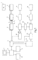
- Fig. 1, 1 denotes a schematically illustrated main field magnet, which in an examination area, not shown, in the z direction running, stationary and essentially homogeneous magnetic field with a Strength of e.g. Generated 1.5 Tesla.
- the z direction is horizontal and in Longitudinal direction of an examination table, not shown, on which a patient is found during an MRI scan.
- a gradient coil arrangement 2 which comprises three coil systems with which magnetic gradient fields G x , G y or G z running in the z direction can be generated with a gradient in the x, y or z direction. If gradient fields with a gradient that do not coincide with the x, y or z direction are to be generated with this gradient coil arrangement, two or three of the gradient coil systems must be effective at the same time.
- the time course of the magnetic gradient fields is specified by a waveform generator - specifically for each of the x, y and z directions.
- the waveform generator 4 is controlled by an arithmetic and control unit 5 which, after specifying the examination method (for example an EPI sequence) and its geometric parameters (for example the position of the layer to be imaged), the required time profile of the magnetic gradient fields G x , G y , G z calculated and loaded into the waveform generator.
- the examination method for example an EPI sequence
- its geometric parameters for example the position of the layer to be imaged
- these signals are read out of the waveform generator and fed to a gradient amplifier arrangement 3, which uses them to generate the currents required for the gradient coil arrangement 2.
- the control unit 5 also interacts with a workstation 6.
- the Workstation is provided with a monitor 7 for the reproduction of MR images.
- a keyboard 8 or an interactive input unit 9, e.g. a light pen entries are possible, e.g. the specification of an MR examination apply MR method, the position of the layers to be imaged, etc.
- the nuclear magnetization in the examination area can be caused by high-frequency pulses a high-frequency coil 10 are excited, which are connected to a high-frequency amplifier 11 is connected, the output signals of a radio frequency transmitter 12th strengthened.
- the high-frequency transmitter 12 the (complex) envelopes of the High frequency pulses with those supplied by an oscillator 13 Carrier vibrations modulated, the frequency of the Larmor frequency (at a Main magnetic field of 1.5 Tesla approx. 63 MHz) corresponds.
- the (complex) envelope is loaded by the computing and control unit 5 into a generator 14 which is connected to the transmitter 12 is coupled.
- the MR signals generated in the examination area are generated by a Receiving coil 20 recorded and amplified by an amplifier 21.
- the amplified MR signal is in a quadrature demodulator 22 by two by 90 ° mutually offset carrier vibrations of the oscillator demodulated, so that two signals are generated, the real part and the imaginary part of a complex MR signal can be understood.
- These signals are an analog-to-digital converter 23 supplied, which forms MR data therefrom - if the control unit 5 him not blocked.
- the MR data are stored in a reconstruction unit 24 saved and corrected in cooperation with the workstation 6 from the MR data derived from a large number of MR signals reconstructed, which represent the nuclear magnetization in the examination area.
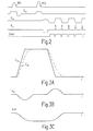
- the sequence comprises two high-frequency excitation pulses RF1 and RF2 (1st line) which, in conjunction with a magnetic gradient field G w (2nd line) running in the w direction, the nuclear magnetization in a layer perpendicular to the w direction by 90 ° or Tilt 180 ° out of its rest position. Then an alternating reading gradient G u running in the u direction becomes effective (3rd line) and a phase coding gradient G v running in the v direction (4th line), which only takes effect during the polarity change of the reading gradient G u .
- an MR signal is detected (5th line), ie the computing and control unit 5 then releases the analog-digital converter 23, so that the received ones MR signals can be converted into MR data.
- Fig. 4 shows the three mutually perpendicular directions u, v, w in the x, y, z coordinate system.
- the direction u of the reading gradient and the direction v of the phase encoding gradient include an angle deviating from 90 ° with the z direction, as does the w direction in which the normal runs to the layer excited by the pulses RF1 and RF2.
- the size of the components must be determined from the transformation matrix shown in Fig. 4b.
- this transformation matrix shows the components from which the gradients G u , G v and G w are composed.
- a magnetic gradient field G u with a certain gradient strength is then obtained, for example, if the magnetic gradient fields G x , G y and G z with the fraction a 1 , b 1 and c 1 of this gradient strength are effective.
- the transformation matrix shows how large the gradient fields G u , G v or G w are if only one of the gradient fields G x , G y or G z is effective (for example, components of the magnetic gradient field result in u-, v- and w direction with the relative size c 1 , c 2 , c 3 if a magnetic gradient field in the z direction with size 1 is switched on).
- the elements a 1 , a 2 and a 3 are each defined by the cosine of the angle which the axes u, v, w enclose with the axis x; the elements b 1 , b 2 , b 3 accordingly represent the direction cosines of the direction of u, v, w with the y axis and c 1 , c 2 , c 3 the respective direction cosines between u, v, w on the one hand and z on the other ,
- the sum of the squares of the three elements contained in a row or column of the transformation matrix is known to be 1.
- the time profiles of G w , G u , G v shown in lines 2 to 4 in FIG. 2 represent the time profile of these variables specified via the control unit 5 or the waveform generator 4.
- the actual profile of the magnetic gradient fields deviates due to the frequency response of components 3, 2 (see FIG. 1). This effect and the resulting consequences are explained below with reference to FIGS. 3a, 3b and 3c.
- 3a shows the time profile of G u in solid lines, ie the profile of the magnetic gradient field in the u direction that is predetermined or desired (by the control unit 5 or the waveform generator 4).
- the actual course G ur of the magnetic gradient field is shown with dashed lines in FIG. 3a, which results because the various gradient systems cannot follow the predetermined time course without delay. Problems may arise from this if there are x, y or. z-direction result in different delays.
- a magnetic gradient field with a gradient extending in the u direction can only be generated if the strength of the magnetic gradient fields G x , G y , and G z corresponds to the elements a 1 , b 1 , c 1 of the transformation matrix behaves.
- This condition is not fulfilled as long as the magnetic gradient fields G x , G y and G z generated by the gradient coil arrangement 2 have not reached their value specified by the waveform generator 4 and are approaching this with different temporal behavior.
- Components of the magnetic gradient field that have a gradient in the v or w direction therefore also occur in these time segments. This means, for example, that although no magnetic gradient field in the w direction is specified at the relevant point in time, the magnetic gradient G u is accompanied by such a gradient G w which is perpendicular to the selected layer.
- c 1 ... c 3 and b 1 ... b 3 are the elements of the transformation matrix of FIG. 4b, while G u (t) and G v (t) are the predetermined (desired) temporal course of the magnetic gradient field in u - or v direction.
- the operator * symbolizes convolution.
- I x , I y and I z are the impulse responses of the channels for the x, y and z directions in units 2 and 3.
- the impulse response is predetermined by the structure of the gradient coil arrangement 2 and the amplifier arrangement 3. It represents the temporal course of the magnetic gradient field when a so-called Dirac impact is specified at the input, ie a signal that jumps to a high value in an abrupt manner and immediately disappears again. In practice, such a Dirac shock cannot be generated because it should have an infinite amplitude and a duration of zero. Nevertheless, the impulse response can be determined by measuring the time profile of a suitable excitation variable at the input (input variable) of one of the gradient amplifiers 3 and the time profile of the magnetic gradient field (output variable), which is then generated by the gradient coil 2 connected to the gradient amplifier.
- Equation 1 when the gradients G u (t) and G v (t) running in the layer plane are applied, the gradient G w (t) running perpendicular to the layer would not arise if the three channels for the x, y, z direction would have identical impulse responses I x , I y , I z . This requirement is usually not met. Although there is usually an identical time profile for the x and y directions (so that the second of the two summands in equation (1) disappears), the time behavior of the gradient systems 2, 3 is different for the x and y Direction depends on the temporal behavior for the z direction. It can further be seen from equation (1) that in the latter case the gradient field perpendicular to the layer plane does not occur even if c 3 is zero, ie if the layer normal w runs perpendicular to the z direction.
- FIG. 3b shows the course over time of the magnetic gradient field G w (t), which is caused by the gradient G u according to FIG. 3a. It can be seen that the interfering gradient G x (t) occurs simultaneously with the actual gradient in the u direction G ur , and as long as this deviates from the predetermined time profile G u .
- the occurrence of the disturbing component G w (t) means that the so-called k-space is not scanned along a u, v plane, but along a non-flat surface.
- the following applies to the component k w (t) in k-space k w (t) ⁇ G w (t) German
- Block 101 includes the initialization and, among other things, the generation of the high-frequency pulses RF1 and RF2.
- An MR signal is then detected at the positive and negative polarities of the reading gradient G u and converted into a sequence of MR data (block 102).
- block 103 the time profile of the magnetic gradient field G w (t) perpendicular to the layer plane is calculated in accordance with equation (1).
- the value k w (t) resulting therefrom according to equation (2) is calculated from the calculated value in block 104, with which the value for the phase error ⁇ according to equation (3) can be calculated in block 105.
- the measured time profile of the signal S (t) is corrected in accordance with the calculated time profile by adding the calculated phase error and the signal phase, which results from the time profile of the measured MR signal S (t), to one another.
- the result is, according to equation (4), the MR signal S 0 (t), which is freed from the phase error.
- Calculation steps 103 and 105 use values (a 1 ... c 3 ; G u (t) ...; I x ... I z ) that are known at the start of the MR examination. This calculation can therefore already take place before the MR signal is acquired (block 102), so that the MR signal can be corrected immediately after its measurement.
- the nuclear magnetization distribution M (u, v) within the excited layer is reconstructed from the corrected MR signals S 0 (t). It must be taken into account that the same effect, which causes the disturbing gradient G w (t) in connection with the reading gradient G u (t), also generates an undesirable magnetic gradient field in the v-direction, which falsifies the phase coding , This falsification can be taken into account by increasing or decreasing the "blips" of the gradient G v accordingly, as explained in the publications mentioned at the beginning, or by using a reconstruction method which does not require an even distribution of the MR data in k-space , such as the well-known gridding process.
- the method ends in block 108.
- the invention has been explained above in connection with an EPI sequence. However, the invention can also be used in other MR methods in which the image information is derived from the MR data in a phase-sensitive manner.
- the artifacts (ghost images, blurring, etc.) associated with the undesired gradients G w (t) depend on the respective MR method.
Landscapes
- Physics & Mathematics (AREA)
- Condensed Matter Physics & Semiconductors (AREA)
- General Physics & Mathematics (AREA)
- High Energy & Nuclear Physics (AREA)
- Health & Medical Sciences (AREA)
- Spectroscopy & Molecular Physics (AREA)
- Optics & Photonics (AREA)
- General Health & Medical Sciences (AREA)
- Nuclear Medicine, Radiotherapy & Molecular Imaging (AREA)
- Radiology & Medical Imaging (AREA)
- Engineering & Computer Science (AREA)
- Signal Processing (AREA)
- Magnetic Resonance Imaging Apparatus (AREA)
Applications Claiming Priority (2)
| Application Number | Priority Date | Filing Date | Title |
|---|---|---|---|
| DE19631845 | 1996-08-07 | ||
| DE19631845 | 1996-08-07 |
Publications (2)
| Publication Number | Publication Date |
|---|---|
| EP0823642A1 EP0823642A1 (de) | 1998-02-11 |
| EP0823642B1 true EP0823642B1 (de) | 2003-04-23 |
Family
ID=7802006
Family Applications (1)
| Application Number | Title | Priority Date | Filing Date |
|---|---|---|---|
| EP97202430A Expired - Lifetime EP0823642B1 (de) | 1996-08-07 | 1997-08-04 | MR-Verfahren und Anordnung zur Durchführung des Verfahrens |
Country Status (4)
| Country | Link |
|---|---|
| US (1) | US5929638A (https=) |
| EP (1) | EP0823642B1 (https=) |
| JP (1) | JP3898294B2 (https=) |
| DE (1) | DE59709890D1 (https=) |
Families Citing this family (4)
| Publication number | Priority date | Publication date | Assignee | Title |
|---|---|---|---|---|
| US6201987B1 (en) * | 1998-05-26 | 2001-03-13 | General Electric Company | Error compensation for device tracking systems employing electromagnetic fields |
| DE19826864A1 (de) * | 1998-06-17 | 1999-12-23 | Philips Patentverwaltung | MR-Verfahren |
| CA2648310C (en) * | 2006-04-12 | 2016-10-18 | Thomson Licensing | Virtual dvd on demand and electronic dvd rental/buy/burn |
| EP3447520A1 (en) * | 2017-08-22 | 2019-02-27 | Koninklijke Philips N.V. | Data-driven correction of phase depending artefacts in a magnetic resonance imaging system |
Family Cites Families (3)
| Publication number | Priority date | Publication date | Assignee | Title |
|---|---|---|---|---|
| US4585995A (en) * | 1984-04-19 | 1986-04-29 | Technicare Corporation | Nuclear magnetic resonance eddy field suppression apparatus |
| EP0216523A3 (en) * | 1985-08-27 | 1989-04-05 | Resonex, Inc. | Process for non-orthogonal nmr imaging |
| US4698591A (en) * | 1986-01-03 | 1987-10-06 | General Electric Company | Method for magnetic field gradient eddy current compensation |
-
1997
- 1997-07-18 US US08/896,759 patent/US5929638A/en not_active Expired - Fee Related
- 1997-08-04 JP JP20933897A patent/JP3898294B2/ja not_active Expired - Fee Related
- 1997-08-04 EP EP97202430A patent/EP0823642B1/de not_active Expired - Lifetime
- 1997-08-04 DE DE59709890T patent/DE59709890D1/de not_active Expired - Fee Related
Also Published As
| Publication number | Publication date |
|---|---|
| EP0823642A1 (de) | 1998-02-11 |
| JP3898294B2 (ja) | 2007-03-28 |
| DE59709890D1 (de) | 2003-05-28 |
| JPH1071135A (ja) | 1998-03-17 |
| US5929638A (en) | 1999-07-27 |
Similar Documents
| Publication | Publication Date | Title |
|---|---|---|
| EP0695947B1 (de) | MR-Verfahren zur Bestimmung der Kernmagnetisierungsverteilung mit einer Oberflächenspulen-Anordnung | |
| EP0088970B1 (de) | Verfahren zum Messen der magnetischen Kernresonanz für die NMR-Tomographie | |
| EP0200049B1 (de) | Verfahren und Vorrichtung zur Zusammensetzung eines MR-Bildes aus atemgesteuert aufgenommenen Bilddaten | |
| EP0629876B1 (de) | Verfahren zur Erzeugung einer MR-Bildfolge und Anordnung zur Durchführung des Verfahren | |
| EP0793113B1 (de) | MR-Verfahren mit reduzierten Bewegungsartefakten | |
| DE3411222A1 (de) | Kernspintomograph | |
| EP0226247A2 (de) | Kernspintomographieverfahren und Anordnung zur Durchführung des Verfahrens | |
| DE102010043956B4 (de) | Erfassung von MR-Daten in einem vorbestimmten dreidimensionalen Volumenabschnitt unter Vermeidung von Einfaltungs- und Bandartefakten | |
| DE3710748A1 (de) | Magnetresonanz-abbildungsanordnung | |
| DE102014205004B3 (de) | Verfahren und Magnetresonanzanlage zum Erfassen von MR-Daten einer Schicht eines Volumenabschnitts innerhalb eines Untersuchungsobjekts | |
| EP0789251B1 (de) | MR-Verfahren zur Bestimmung der Magnetfeldinhomogenität im Untersuchungsbereich und MR-Gerät zur Durchführung des Verfahrens | |
| DE102014206561B4 (de) | Erfassen von MR-Daten mit unterschiedlichen Echozeiten | |
| EP0404248A2 (de) | Kernresonanzabbildungsverfahren | |
| DE19801492A1 (de) | Korrektur von Artefakten, die durch Maxwellterme bei einer Phasenkontrastangiographie verursacht werden | |
| DE3728797C2 (https=) | ||
| EP0259935B1 (de) | Kernspintomographiverfahren und Kernspintomograph zur Durchführung des Verfahrens | |
| EP0357100A2 (de) | Kernspintomographieverfahren und Kernspintomograph zur Durchführung des Verfahrens | |
| EP0322006A2 (de) | Kernresonanz-Spektroskopieverfahren | |
| EP0823642B1 (de) | MR-Verfahren und Anordnung zur Durchführung des Verfahrens | |
| EP0981762A1 (de) | Mr-verfahren | |
| DE3542215A1 (de) | Kernspintomographieverfahren und anordnung zur durchfuehrung des verfahrens | |
| EP0965854B1 (de) | Korrektur von Phasenfehlern durch begleitende Gradienten in der Magnetresonanzbildgebung | |
| DE3938370A1 (de) | Kernspintomographieverfahren und kernspintomograph zur durchfuehrung des verfahrens | |
| EP0369538B1 (de) | Kernspintomographieverfahren zur Bestimmung der Kernmagnetisierung in einer Anzahl paralleler Schichten | |
| DE112019001281T5 (de) | Mr-bildgebung mit spiralerfassung |
Legal Events
| Date | Code | Title | Description |
|---|---|---|---|
| PUAI | Public reference made under article 153(3) epc to a published international application that has entered the european phase |
Free format text: ORIGINAL CODE: 0009012 |
|
| AK | Designated contracting states |
Kind code of ref document: A1 Designated state(s): DE FR GB NL |
|
| RAP3 | Party data changed (applicant data changed or rights of an application transferred) |
Owner name: KONINKLIJKE PHILIPS ELECTRONICS N.V. Owner name: PHILIPS PATENTVERWALTUNG GMBH |
|
| 17P | Request for examination filed |
Effective date: 19980811 |
|
| AKX | Designation fees paid |
Free format text: DE FR GB NL |
|
| RBV | Designated contracting states (corrected) |
Designated state(s): DE FR GB NL |
|
| RAP3 | Party data changed (applicant data changed or rights of an application transferred) |
Owner name: KONINKLIJKE PHILIPS ELECTRONICS N.V. Owner name: PHILIPS CORPORATE INTELLECTUAL PROPERTY GMBH |
|
| 17Q | First examination report despatched |
Effective date: 20020214 |
|
| GRAG | Despatch of communication of intention to grant |
Free format text: ORIGINAL CODE: EPIDOS AGRA |
|
| RAP1 | Party data changed (applicant data changed or rights of an application transferred) |
Owner name: KONINKLIJKE PHILIPS ELECTRONICS N.V. Owner name: PHILIPS CORPORATE INTELLECTUAL PROPERTY GMBH |
|
| GRAG | Despatch of communication of intention to grant |
Free format text: ORIGINAL CODE: EPIDOS AGRA |
|
| GRAH | Despatch of communication of intention to grant a patent |
Free format text: ORIGINAL CODE: EPIDOS IGRA |
|
| GRAH | Despatch of communication of intention to grant a patent |
Free format text: ORIGINAL CODE: EPIDOS IGRA |
|
| GRAA | (expected) grant |
Free format text: ORIGINAL CODE: 0009210 |
|
| AK | Designated contracting states |
Designated state(s): DE FR GB NL |
|
| PG25 | Lapsed in a contracting state [announced via postgrant information from national office to epo] |
Ref country code: NL Free format text: LAPSE BECAUSE OF FAILURE TO SUBMIT A TRANSLATION OF THE DESCRIPTION OR TO PAY THE FEE WITHIN THE PRESCRIBED TIME-LIMIT Effective date: 20030423 Ref country code: FR Free format text: LAPSE BECAUSE OF FAILURE TO SUBMIT A TRANSLATION OF THE DESCRIPTION OR TO PAY THE FEE WITHIN THE PRESCRIBED TIME-LIMIT Effective date: 20030423 |
|
| REG | Reference to a national code |
Ref country code: GB Ref legal event code: FG4D Free format text: NOT ENGLISH |
|
| RAP2 | Party data changed (patent owner data changed or rights of a patent transferred) |
Owner name: KONINKLIJKE PHILIPS ELECTRONICS N.V. Owner name: PHILIPS INTELLECTUAL PROPERTY & STANDARDS GMBH |
|
| REF | Corresponds to: |
Ref document number: 59709890 Country of ref document: DE Date of ref document: 20030528 Kind code of ref document: P |
|
| NLT2 | Nl: modifications (of names), taken from the european patent patent bulletin |
Owner name: KONINKLIJKE PHILIPS ELECTRONICS N.V. |
|
| GBT | Gb: translation of ep patent filed (gb section 77(6)(a)/1977) | ||
| REG | Reference to a national code |
Ref country code: GB Ref legal event code: 746 Effective date: 20030624 |
|
| NLV1 | Nl: lapsed or annulled due to failure to fulfill the requirements of art. 29p and 29m of the patents act | ||
| PLBE | No opposition filed within time limit |
Free format text: ORIGINAL CODE: 0009261 |
|
| STAA | Information on the status of an ep patent application or granted ep patent |
Free format text: STATUS: NO OPPOSITION FILED WITHIN TIME LIMIT |
|
| 26N | No opposition filed |
Effective date: 20040126 |
|
| EN | Fr: translation not filed | ||
| PGFP | Annual fee paid to national office [announced via postgrant information from national office to epo] |
Ref country code: GB Payment date: 20070925 Year of fee payment: 11 |
|
| PGFP | Annual fee paid to national office [announced via postgrant information from national office to epo] |
Ref country code: DE Payment date: 20071015 Year of fee payment: 11 |
|
| GBPC | Gb: european patent ceased through non-payment of renewal fee |
Effective date: 20080804 |
|
| PG25 | Lapsed in a contracting state [announced via postgrant information from national office to epo] |
Ref country code: DE Free format text: LAPSE BECAUSE OF NON-PAYMENT OF DUE FEES Effective date: 20090303 |
|
| PG25 | Lapsed in a contracting state [announced via postgrant information from national office to epo] |
Ref country code: GB Free format text: LAPSE BECAUSE OF NON-PAYMENT OF DUE FEES Effective date: 20080804 |