EP0823321B1 - Joining thermoplastic cases and covers by fusion - Google Patents
Joining thermoplastic cases and covers by fusion Download PDFInfo
- Publication number
- EP0823321B1 EP0823321B1 EP19970306022 EP97306022A EP0823321B1 EP 0823321 B1 EP0823321 B1 EP 0823321B1 EP 19970306022 EP19970306022 EP 19970306022 EP 97306022 A EP97306022 A EP 97306022A EP 0823321 B1 EP0823321 B1 EP 0823321B1
- Authority
- EP
- European Patent Office
- Prior art keywords
- heating element
- casing
- apertures
- parts
- electrodes
- Prior art date
- Legal status (The legal status is an assumption and is not a legal conclusion. Google has not performed a legal analysis and makes no representation as to the accuracy of the status listed.)
- Expired - Lifetime
Links
Images






Classifications
-
- B—PERFORMING OPERATIONS; TRANSPORTING
- B29—WORKING OF PLASTICS; WORKING OF SUBSTANCES IN A PLASTIC STATE IN GENERAL
- B29C—SHAPING OR JOINING OF PLASTICS; SHAPING OF MATERIAL IN A PLASTIC STATE, NOT OTHERWISE PROVIDED FOR; AFTER-TREATMENT OF THE SHAPED PRODUCTS, e.g. REPAIRING
- B29C65/00—Joining or sealing of preformed parts, e.g. welding of plastics materials; Apparatus therefor
- B29C65/02—Joining or sealing of preformed parts, e.g. welding of plastics materials; Apparatus therefor by heating, with or without pressure
- B29C65/34—Joining or sealing of preformed parts, e.g. welding of plastics materials; Apparatus therefor by heating, with or without pressure using heated elements which remain in the joint, e.g. "verlorenes Schweisselement"
- B29C65/3404—Joining or sealing of preformed parts, e.g. welding of plastics materials; Apparatus therefor by heating, with or without pressure using heated elements which remain in the joint, e.g. "verlorenes Schweisselement" characterised by the type of heated elements which remain in the joint
- B29C65/3444—Joining or sealing of preformed parts, e.g. welding of plastics materials; Apparatus therefor by heating, with or without pressure using heated elements which remain in the joint, e.g. "verlorenes Schweisselement" characterised by the type of heated elements which remain in the joint being a ribbon, band or strip
-
- B—PERFORMING OPERATIONS; TRANSPORTING
- B29—WORKING OF PLASTICS; WORKING OF SUBSTANCES IN A PLASTIC STATE IN GENERAL
- B29C—SHAPING OR JOINING OF PLASTICS; SHAPING OF MATERIAL IN A PLASTIC STATE, NOT OTHERWISE PROVIDED FOR; AFTER-TREATMENT OF THE SHAPED PRODUCTS, e.g. REPAIRING
- B29C65/00—Joining or sealing of preformed parts, e.g. welding of plastics materials; Apparatus therefor
- B29C65/02—Joining or sealing of preformed parts, e.g. welding of plastics materials; Apparatus therefor by heating, with or without pressure
- B29C65/34—Joining or sealing of preformed parts, e.g. welding of plastics materials; Apparatus therefor by heating, with or without pressure using heated elements which remain in the joint, e.g. "verlorenes Schweisselement"
- B29C65/3404—Joining or sealing of preformed parts, e.g. welding of plastics materials; Apparatus therefor by heating, with or without pressure using heated elements which remain in the joint, e.g. "verlorenes Schweisselement" characterised by the type of heated elements which remain in the joint
- B29C65/342—Joining or sealing of preformed parts, e.g. welding of plastics materials; Apparatus therefor by heating, with or without pressure using heated elements which remain in the joint, e.g. "verlorenes Schweisselement" characterised by the type of heated elements which remain in the joint comprising at least a single wire, e.g. in the form of a winding
-
- B—PERFORMING OPERATIONS; TRANSPORTING
- B29—WORKING OF PLASTICS; WORKING OF SUBSTANCES IN A PLASTIC STATE IN GENERAL
- B29C—SHAPING OR JOINING OF PLASTICS; SHAPING OF MATERIAL IN A PLASTIC STATE, NOT OTHERWISE PROVIDED FOR; AFTER-TREATMENT OF THE SHAPED PRODUCTS, e.g. REPAIRING
- B29C65/00—Joining or sealing of preformed parts, e.g. welding of plastics materials; Apparatus therefor
- B29C65/02—Joining or sealing of preformed parts, e.g. welding of plastics materials; Apparatus therefor by heating, with or without pressure
- B29C65/34—Joining or sealing of preformed parts, e.g. welding of plastics materials; Apparatus therefor by heating, with or without pressure using heated elements which remain in the joint, e.g. "verlorenes Schweisselement"
- B29C65/3468—Joining or sealing of preformed parts, e.g. welding of plastics materials; Apparatus therefor by heating, with or without pressure using heated elements which remain in the joint, e.g. "verlorenes Schweisselement" characterised by the means for supplying heat to said heated elements which remain in the join, e.g. special electrical connectors of windings
-
- B—PERFORMING OPERATIONS; TRANSPORTING
- B29—WORKING OF PLASTICS; WORKING OF SUBSTANCES IN A PLASTIC STATE IN GENERAL
- B29C—SHAPING OR JOINING OF PLASTICS; SHAPING OF MATERIAL IN A PLASTIC STATE, NOT OTHERWISE PROVIDED FOR; AFTER-TREATMENT OF THE SHAPED PRODUCTS, e.g. REPAIRING
- B29C65/00—Joining or sealing of preformed parts, e.g. welding of plastics materials; Apparatus therefor
- B29C65/02—Joining or sealing of preformed parts, e.g. welding of plastics materials; Apparatus therefor by heating, with or without pressure
- B29C65/34—Joining or sealing of preformed parts, e.g. welding of plastics materials; Apparatus therefor by heating, with or without pressure using heated elements which remain in the joint, e.g. "verlorenes Schweisselement"
- B29C65/36—Joining or sealing of preformed parts, e.g. welding of plastics materials; Apparatus therefor by heating, with or without pressure using heated elements which remain in the joint, e.g. "verlorenes Schweisselement" heated by induction
- B29C65/3604—Joining or sealing of preformed parts, e.g. welding of plastics materials; Apparatus therefor by heating, with or without pressure using heated elements which remain in the joint, e.g. "verlorenes Schweisselement" heated by induction characterised by the type of elements heated by induction which remain in the joint
- B29C65/3644—Joining or sealing of preformed parts, e.g. welding of plastics materials; Apparatus therefor by heating, with or without pressure using heated elements which remain in the joint, e.g. "verlorenes Schweisselement" heated by induction characterised by the type of elements heated by induction which remain in the joint being a ribbon, band or strip
-
- B—PERFORMING OPERATIONS; TRANSPORTING
- B29—WORKING OF PLASTICS; WORKING OF SUBSTANCES IN A PLASTIC STATE IN GENERAL
- B29C—SHAPING OR JOINING OF PLASTICS; SHAPING OF MATERIAL IN A PLASTIC STATE, NOT OTHERWISE PROVIDED FOR; AFTER-TREATMENT OF THE SHAPED PRODUCTS, e.g. REPAIRING
- B29C66/00—General aspects of processes or apparatus for joining preformed parts
- B29C66/01—General aspects dealing with the joint area or with the area to be joined
- B29C66/05—Particular design of joint configurations
- B29C66/10—Particular design of joint configurations particular design of the joint cross-sections
- B29C66/11—Joint cross-sections comprising a single joint-segment, i.e. one of the parts to be joined comprising a single joint-segment in the joint cross-section
- B29C66/114—Single butt joints
- B29C66/1142—Single butt to butt joints
-
- B—PERFORMING OPERATIONS; TRANSPORTING
- B29—WORKING OF PLASTICS; WORKING OF SUBSTANCES IN A PLASTIC STATE IN GENERAL
- B29C—SHAPING OR JOINING OF PLASTICS; SHAPING OF MATERIAL IN A PLASTIC STATE, NOT OTHERWISE PROVIDED FOR; AFTER-TREATMENT OF THE SHAPED PRODUCTS, e.g. REPAIRING
- B29C66/00—General aspects of processes or apparatus for joining preformed parts
- B29C66/01—General aspects dealing with the joint area or with the area to be joined
- B29C66/05—Particular design of joint configurations
- B29C66/10—Particular design of joint configurations particular design of the joint cross-sections
- B29C66/12—Joint cross-sections combining only two joint-segments; Tongue and groove joints; Tenon and mortise joints; Stepped joint cross-sections
- B29C66/124—Tongue and groove joints
- B29C66/1244—Tongue and groove joints characterised by the male part, i.e. the part comprising the tongue
- B29C66/12445—Tongue and groove joints characterised by the male part, i.e. the part comprising the tongue having the tongue on the side
-
- B—PERFORMING OPERATIONS; TRANSPORTING
- B29—WORKING OF PLASTICS; WORKING OF SUBSTANCES IN A PLASTIC STATE IN GENERAL
- B29C—SHAPING OR JOINING OF PLASTICS; SHAPING OF MATERIAL IN A PLASTIC STATE, NOT OTHERWISE PROVIDED FOR; AFTER-TREATMENT OF THE SHAPED PRODUCTS, e.g. REPAIRING
- B29C66/00—General aspects of processes or apparatus for joining preformed parts
- B29C66/01—General aspects dealing with the joint area or with the area to be joined
- B29C66/05—Particular design of joint configurations
- B29C66/10—Particular design of joint configurations particular design of the joint cross-sections
- B29C66/12—Joint cross-sections combining only two joint-segments; Tongue and groove joints; Tenon and mortise joints; Stepped joint cross-sections
- B29C66/124—Tongue and groove joints
- B29C66/1244—Tongue and groove joints characterised by the male part, i.e. the part comprising the tongue
- B29C66/12449—Tongue and groove joints characterised by the male part, i.e. the part comprising the tongue being asymmetric
-
- B—PERFORMING OPERATIONS; TRANSPORTING
- B29—WORKING OF PLASTICS; WORKING OF SUBSTANCES IN A PLASTIC STATE IN GENERAL
- B29C—SHAPING OR JOINING OF PLASTICS; SHAPING OF MATERIAL IN A PLASTIC STATE, NOT OTHERWISE PROVIDED FOR; AFTER-TREATMENT OF THE SHAPED PRODUCTS, e.g. REPAIRING
- B29C66/00—General aspects of processes or apparatus for joining preformed parts
- B29C66/01—General aspects dealing with the joint area or with the area to be joined
- B29C66/05—Particular design of joint configurations
- B29C66/10—Particular design of joint configurations particular design of the joint cross-sections
- B29C66/12—Joint cross-sections combining only two joint-segments; Tongue and groove joints; Tenon and mortise joints; Stepped joint cross-sections
- B29C66/124—Tongue and groove joints
- B29C66/1246—Tongue and groove joints characterised by the female part, i.e. the part comprising the groove
- B29C66/12463—Tongue and groove joints characterised by the female part, i.e. the part comprising the groove being tapered
-
- B—PERFORMING OPERATIONS; TRANSPORTING
- B29—WORKING OF PLASTICS; WORKING OF SUBSTANCES IN A PLASTIC STATE IN GENERAL
- B29C—SHAPING OR JOINING OF PLASTICS; SHAPING OF MATERIAL IN A PLASTIC STATE, NOT OTHERWISE PROVIDED FOR; AFTER-TREATMENT OF THE SHAPED PRODUCTS, e.g. REPAIRING
- B29C66/00—General aspects of processes or apparatus for joining preformed parts
- B29C66/01—General aspects dealing with the joint area or with the area to be joined
- B29C66/05—Particular design of joint configurations
- B29C66/10—Particular design of joint configurations particular design of the joint cross-sections
- B29C66/12—Joint cross-sections combining only two joint-segments; Tongue and groove joints; Tenon and mortise joints; Stepped joint cross-sections
- B29C66/124—Tongue and groove joints
- B29C66/1246—Tongue and groove joints characterised by the female part, i.e. the part comprising the groove
- B29C66/12469—Tongue and groove joints characterised by the female part, i.e. the part comprising the groove being asymmetric
-
- B—PERFORMING OPERATIONS; TRANSPORTING
- B29—WORKING OF PLASTICS; WORKING OF SUBSTANCES IN A PLASTIC STATE IN GENERAL
- B29C—SHAPING OR JOINING OF PLASTICS; SHAPING OF MATERIAL IN A PLASTIC STATE, NOT OTHERWISE PROVIDED FOR; AFTER-TREATMENT OF THE SHAPED PRODUCTS, e.g. REPAIRING
- B29C66/00—General aspects of processes or apparatus for joining preformed parts
- B29C66/01—General aspects dealing with the joint area or with the area to be joined
- B29C66/05—Particular design of joint configurations
- B29C66/10—Particular design of joint configurations particular design of the joint cross-sections
- B29C66/12—Joint cross-sections combining only two joint-segments; Tongue and groove joints; Tenon and mortise joints; Stepped joint cross-sections
- B29C66/128—Stepped joint cross-sections
- B29C66/1282—Stepped joint cross-sections comprising at least one overlap joint-segment
- B29C66/12821—Stepped joint cross-sections comprising at least one overlap joint-segment comprising at least two overlap joint-segments
-
- B—PERFORMING OPERATIONS; TRANSPORTING
- B29—WORKING OF PLASTICS; WORKING OF SUBSTANCES IN A PLASTIC STATE IN GENERAL
- B29C—SHAPING OR JOINING OF PLASTICS; SHAPING OF MATERIAL IN A PLASTIC STATE, NOT OTHERWISE PROVIDED FOR; AFTER-TREATMENT OF THE SHAPED PRODUCTS, e.g. REPAIRING
- B29C66/00—General aspects of processes or apparatus for joining preformed parts
- B29C66/01—General aspects dealing with the joint area or with the area to be joined
- B29C66/05—Particular design of joint configurations
- B29C66/10—Particular design of joint configurations particular design of the joint cross-sections
- B29C66/12—Joint cross-sections combining only two joint-segments; Tongue and groove joints; Tenon and mortise joints; Stepped joint cross-sections
- B29C66/128—Stepped joint cross-sections
- B29C66/1284—Stepped joint cross-sections comprising at least one butt joint-segment
- B29C66/12841—Stepped joint cross-sections comprising at least one butt joint-segment comprising at least two butt joint-segments
- B29C66/12842—Stepped joint cross-sections comprising at least one butt joint-segment comprising at least two butt joint-segments comprising at least three butt joint-segments
-
- B—PERFORMING OPERATIONS; TRANSPORTING
- B29—WORKING OF PLASTICS; WORKING OF SUBSTANCES IN A PLASTIC STATE IN GENERAL
- B29C—SHAPING OR JOINING OF PLASTICS; SHAPING OF MATERIAL IN A PLASTIC STATE, NOT OTHERWISE PROVIDED FOR; AFTER-TREATMENT OF THE SHAPED PRODUCTS, e.g. REPAIRING
- B29C66/00—General aspects of processes or apparatus for joining preformed parts
- B29C66/50—General aspects of joining tubular articles; General aspects of joining long products, i.e. bars or profiled elements; General aspects of joining single elements to tubular articles, hollow articles or bars; General aspects of joining several hollow-preforms to form hollow or tubular articles
- B29C66/51—Joining tubular articles, profiled elements or bars; Joining single elements to tubular articles, hollow articles or bars; Joining several hollow-preforms to form hollow or tubular articles
- B29C66/54—Joining several hollow-preforms, e.g. half-shells, to form hollow articles, e.g. for making balls, containers; Joining several hollow-preforms, e.g. half-cylinders, to form tubular articles
-
- B—PERFORMING OPERATIONS; TRANSPORTING
- B29—WORKING OF PLASTICS; WORKING OF SUBSTANCES IN A PLASTIC STATE IN GENERAL
- B29C—SHAPING OR JOINING OF PLASTICS; SHAPING OF MATERIAL IN A PLASTIC STATE, NOT OTHERWISE PROVIDED FOR; AFTER-TREATMENT OF THE SHAPED PRODUCTS, e.g. REPAIRING
- B29C66/00—General aspects of processes or apparatus for joining preformed parts
- B29C66/50—General aspects of joining tubular articles; General aspects of joining long products, i.e. bars or profiled elements; General aspects of joining single elements to tubular articles, hollow articles or bars; General aspects of joining several hollow-preforms to form hollow or tubular articles
- B29C66/51—Joining tubular articles, profiled elements or bars; Joining single elements to tubular articles, hollow articles or bars; Joining several hollow-preforms to form hollow or tubular articles
- B29C66/54—Joining several hollow-preforms, e.g. half-shells, to form hollow articles, e.g. for making balls, containers; Joining several hollow-preforms, e.g. half-cylinders, to form tubular articles
- B29C66/542—Joining several hollow-preforms, e.g. half-shells, to form hollow articles, e.g. for making balls, containers; Joining several hollow-preforms, e.g. half-cylinders, to form tubular articles joining hollow covers or hollow bottoms to open ends of container bodies
-
- B—PERFORMING OPERATIONS; TRANSPORTING
- B29—WORKING OF PLASTICS; WORKING OF SUBSTANCES IN A PLASTIC STATE IN GENERAL
- B29C—SHAPING OR JOINING OF PLASTICS; SHAPING OF MATERIAL IN A PLASTIC STATE, NOT OTHERWISE PROVIDED FOR; AFTER-TREATMENT OF THE SHAPED PRODUCTS, e.g. REPAIRING
- B29C66/00—General aspects of processes or apparatus for joining preformed parts
- B29C66/80—General aspects of machine operations or constructions and parts thereof
- B29C66/83—General aspects of machine operations or constructions and parts thereof characterised by the movement of the joining or pressing tools
- B29C66/832—Reciprocating joining or pressing tools
- B29C66/8322—Joining or pressing tools reciprocating along one axis
-
- B—PERFORMING OPERATIONS; TRANSPORTING
- B29—WORKING OF PLASTICS; WORKING OF SUBSTANCES IN A PLASTIC STATE IN GENERAL
- B29C—SHAPING OR JOINING OF PLASTICS; SHAPING OF MATERIAL IN A PLASTIC STATE, NOT OTHERWISE PROVIDED FOR; AFTER-TREATMENT OF THE SHAPED PRODUCTS, e.g. REPAIRING
- B29C67/00—Shaping techniques not covered by groups B29C39/00 - B29C65/00, B29C70/00 or B29C73/00
- B29C67/004—Closing perforations or small holes, e.g. using additional moulding material
-
- B—PERFORMING OPERATIONS; TRANSPORTING
- B29—WORKING OF PLASTICS; WORKING OF SUBSTANCES IN A PLASTIC STATE IN GENERAL
- B29C—SHAPING OR JOINING OF PLASTICS; SHAPING OF MATERIAL IN A PLASTIC STATE, NOT OTHERWISE PROVIDED FOR; AFTER-TREATMENT OF THE SHAPED PRODUCTS, e.g. REPAIRING
- B29C57/00—Shaping of tube ends, e.g. flanging, belling or closing; Apparatus therefor, e.g. collapsible mandrels
- B29C57/10—Closing
-
- B—PERFORMING OPERATIONS; TRANSPORTING
- B29—WORKING OF PLASTICS; WORKING OF SUBSTANCES IN A PLASTIC STATE IN GENERAL
- B29C—SHAPING OR JOINING OF PLASTICS; SHAPING OF MATERIAL IN A PLASTIC STATE, NOT OTHERWISE PROVIDED FOR; AFTER-TREATMENT OF THE SHAPED PRODUCTS, e.g. REPAIRING
- B29C65/00—Joining or sealing of preformed parts, e.g. welding of plastics materials; Apparatus therefor
- B29C65/02—Joining or sealing of preformed parts, e.g. welding of plastics materials; Apparatus therefor by heating, with or without pressure
- B29C65/34—Joining or sealing of preformed parts, e.g. welding of plastics materials; Apparatus therefor by heating, with or without pressure using heated elements which remain in the joint, e.g. "verlorenes Schweisselement"
- B29C65/3404—Joining or sealing of preformed parts, e.g. welding of plastics materials; Apparatus therefor by heating, with or without pressure using heated elements which remain in the joint, e.g. "verlorenes Schweisselement" characterised by the type of heated elements which remain in the joint
- B29C65/342—Joining or sealing of preformed parts, e.g. welding of plastics materials; Apparatus therefor by heating, with or without pressure using heated elements which remain in the joint, e.g. "verlorenes Schweisselement" characterised by the type of heated elements which remain in the joint comprising at least a single wire, e.g. in the form of a winding
- B29C65/3432—Joining or sealing of preformed parts, e.g. welding of plastics materials; Apparatus therefor by heating, with or without pressure using heated elements which remain in the joint, e.g. "verlorenes Schweisselement" characterised by the type of heated elements which remain in the joint comprising at least a single wire, e.g. in the form of a winding comprising several wires, e.g. in the form of several independent windings
-
- B—PERFORMING OPERATIONS; TRANSPORTING
- B29—WORKING OF PLASTICS; WORKING OF SUBSTANCES IN A PLASTIC STATE IN GENERAL
- B29C—SHAPING OR JOINING OF PLASTICS; SHAPING OF MATERIAL IN A PLASTIC STATE, NOT OTHERWISE PROVIDED FOR; AFTER-TREATMENT OF THE SHAPED PRODUCTS, e.g. REPAIRING
- B29C65/00—Joining or sealing of preformed parts, e.g. welding of plastics materials; Apparatus therefor
- B29C65/02—Joining or sealing of preformed parts, e.g. welding of plastics materials; Apparatus therefor by heating, with or without pressure
- B29C65/34—Joining or sealing of preformed parts, e.g. welding of plastics materials; Apparatus therefor by heating, with or without pressure using heated elements which remain in the joint, e.g. "verlorenes Schweisselement"
- B29C65/3472—Joining or sealing of preformed parts, e.g. welding of plastics materials; Apparatus therefor by heating, with or without pressure using heated elements which remain in the joint, e.g. "verlorenes Schweisselement" characterised by the composition of the heated elements which remain in the joint
- B29C65/3476—Joining or sealing of preformed parts, e.g. welding of plastics materials; Apparatus therefor by heating, with or without pressure using heated elements which remain in the joint, e.g. "verlorenes Schweisselement" characterised by the composition of the heated elements which remain in the joint being metallic
-
- B—PERFORMING OPERATIONS; TRANSPORTING
- B29—WORKING OF PLASTICS; WORKING OF SUBSTANCES IN A PLASTIC STATE IN GENERAL
- B29C—SHAPING OR JOINING OF PLASTICS; SHAPING OF MATERIAL IN A PLASTIC STATE, NOT OTHERWISE PROVIDED FOR; AFTER-TREATMENT OF THE SHAPED PRODUCTS, e.g. REPAIRING
- B29C65/00—Joining or sealing of preformed parts, e.g. welding of plastics materials; Apparatus therefor
- B29C65/02—Joining or sealing of preformed parts, e.g. welding of plastics materials; Apparatus therefor by heating, with or without pressure
- B29C65/34—Joining or sealing of preformed parts, e.g. welding of plastics materials; Apparatus therefor by heating, with or without pressure using heated elements which remain in the joint, e.g. "verlorenes Schweisselement"
- B29C65/36—Joining or sealing of preformed parts, e.g. welding of plastics materials; Apparatus therefor by heating, with or without pressure using heated elements which remain in the joint, e.g. "verlorenes Schweisselement" heated by induction
- B29C65/3672—Joining or sealing of preformed parts, e.g. welding of plastics materials; Apparatus therefor by heating, with or without pressure using heated elements which remain in the joint, e.g. "verlorenes Schweisselement" heated by induction characterised by the composition of the elements heated by induction which remain in the joint
- B29C65/3676—Joining or sealing of preformed parts, e.g. welding of plastics materials; Apparatus therefor by heating, with or without pressure using heated elements which remain in the joint, e.g. "verlorenes Schweisselement" heated by induction characterised by the composition of the elements heated by induction which remain in the joint being metallic
-
- B—PERFORMING OPERATIONS; TRANSPORTING
- B29—WORKING OF PLASTICS; WORKING OF SUBSTANCES IN A PLASTIC STATE IN GENERAL
- B29C—SHAPING OR JOINING OF PLASTICS; SHAPING OF MATERIAL IN A PLASTIC STATE, NOT OTHERWISE PROVIDED FOR; AFTER-TREATMENT OF THE SHAPED PRODUCTS, e.g. REPAIRING
- B29C66/00—General aspects of processes or apparatus for joining preformed parts
- B29C66/70—General aspects of processes or apparatus for joining preformed parts characterised by the composition, physical properties or the structure of the material of the parts to be joined; Joining with non-plastics material
- B29C66/71—General aspects of processes or apparatus for joining preformed parts characterised by the composition, physical properties or the structure of the material of the parts to be joined; Joining with non-plastics material characterised by the composition of the plastics material of the parts to be joined
-
- B—PERFORMING OPERATIONS; TRANSPORTING
- B29—WORKING OF PLASTICS; WORKING OF SUBSTANCES IN A PLASTIC STATE IN GENERAL
- B29L—INDEXING SCHEME ASSOCIATED WITH SUBCLASS B29C, RELATING TO PARTICULAR ARTICLES
- B29L2031/00—Other particular articles
- B29L2031/712—Containers; Packaging elements or accessories, Packages
- B29L2031/7146—Battery-cases
Definitions
- This invention relates to a method and apparatus for joining and closing a case body with a cover after assembling components such as a battery or other parts into the case body.
- connection may be made using ultrasonic fusion, high frequency electromagnetic induction fusion or by using a bonding agent or adhesive.
- Japanese Unexamined Patent Publication (Kokai) No. S58-59050 and Unexamined Patent Publication (Kokai) No. S62-288029 disclose a method for trapping a heating element between the case body and the cover and fusing the thermoplastic by heating whereby the case and cover are joined. This provides an effective joint without damage to internal components and without affecting the appearance because the process is localised.
- a disadvantage is that an electrode or a resistance heating element conductor by which a supply voltage is applied to the resistance heating element protrudes outside the case and may interfere during assembly of the case into a second casing.
- the protruding electrodes can spoil the outside appearance and provide a hazard thus, for this reason, post-processing becomes necessary to cut off the protruding portion of the electrode and conductor.
- One object of this invention is to provide a method for thermally joining a moulded plastic product formed from a thermoplastic resin using a heating element where the voltage is applied without the ends of the resistance element projecting from the body.
- Another object is to provide a method wherein the body is sealed so that the electrode does not remain exposed to form any gaps in the casing parts.
- a further object is to provide a method wherein the resistance heating element is completely sealed and embedded and where the whole of the plane of the joint is fused.
- a method for connecting together two parts formed of thermoplastic materials using a heat fusion process wherein an electric resistance heating element is located between the parts which are brought together under pressure after which an electric current is passed through the said element sufficient to melt the plastic and fuse the parts together at their junction, characterised in that current applying electrodes are inserted into access apertures provided in a casing part to contact the heating element after which current is applied for the purpose of heating the element to melt and fuse the parts at their junction following which the electrodes are withdrawn from the apertures.
- products are moulded using a thermoplastic resin composition to form, for example, a battery case.
- a groove is formed on a face of the case main body part and a small diameter hole for inserting a voltage applying terminal is provided. This groove and the small diameter hole may also be formed on the side of the cover.
- a protrusion may be formed around the small diameter hole which usually is circular but may be square or rectangular.
- a nickel-chrome alloy, iron-chrome alloy, iron-nickel alloy or the like can be used to form the resistance heating element, and various shapes of single wire or multi-stranded wires, as well as plate shapes and the like may be selected.
- the resistance heating element may preferably be formed in a ring shape in order to fuse and seal the junction all around the circumference between the case main body and the cover.
- a means for forming this resistance heating element into a ring shape both the ends of a single wire rod may be connected and, for example, a thin resistance heating plate may be punched-out using a press for formation into a ring shape.
- the ring shape for the resistance heating element has no free ends and forms a complete fusion seal.
- the resistance heating element is assembled into a groove of the main case and a cover is placed in position with mating rims with the resistance heating element trapped therebetween and pressure applied.
- a voltage is applied by terminals inserted into each of two opposed small diameter holes, contact is made with the resistance heating element, and voltage is applied to heat the resistance heating element, during which plastic around the heating element is fused.
- FIG. 1 shows perspective view of a battery case 10 according to a first embodiment.
- the battery case 10 comprises a cover part 30 located on a main body part 20.
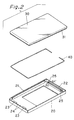
- Figure 2 shows the assembly in exploded view with the battery case 10 comprising main body 20 and the cover 30 which are plastic mouldings formed from a thermoplastic resin.
- An electric resistance heating element 40 locates between the parts.
- a lower lip 31 is formed on the lower edge of cover part 30.
- a channel section 21 is located on opposed sides extending in a longitudinal direction of the main body part 20 and a channel section 22 is located at an end.
- Retainers 23 and a rib 24 are formed for temporarily holding the resistance heating element 40 on the opposing end.
- a small diameter hole 25 is drilled through the bottom face of the main body part 20 in two locations into the channel 22.
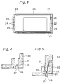
- Figure 3 is a plan view seen from the side of cover 30 showing the resistance heating element 40 fitted into the main body part 20.
- the resistance heating element 40 is located in each channel 21 and in the channel 22 as well as being fixed by the retainers 23 and the rib 24.
- Figure 4 shows the location for applying voltage to the resistance heating element 40 and is a cross-sectional view taken along the line A-A' through the hole 25 shown in Figure 2.
- the small diameter hole 25 is provided at the bottom face of the main body part 20 with a protrusion 26 integrally formed around the hole 25. This defines an electric terminal guide hole 27.
- the internal diameter of the terminal guide hole 27 may be larger than the diameter of hole 25, to make it easier to insert a voltage applying terminal.
- the hole 25 may be formed when moulding the case body part 20 or may be provided afterwards.
- the resistance heating element 40 is first inserted between the retainers 23 and the ribs 24 of the main body part 20 so that the element is trapped and then assembled into the channels 21 and 22.
- the element 40 is thus trapped between the main body 20 and the cover 30 after placing the cover 30 thereon and inserting the lower lip 31 into the channels 21 and 22.
- two voltage applying terminals 50 connected to a voltage supply controller are inserted into the terminal holes 27 respectively and further pass through the small diameter hole 25 to contact the resistance heating element 40, after which power is applied to heat the element 40. Because of factors such as the type of plastic resin used and the size of the case as well as the material and dimensions of the element 40, the heating parameters are predetermined by the voltage supply controller.
- the channel sections 21 and 22 extend along three sides, but the entire circumference can be fused if the channels are provided around the entire circumference and the ends of the resistance heating element 40 are overlapped or a ring shaped resistance heating element 40 is used.
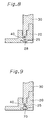
- the tip 60 of a disc shaped contact face is pressed against the tip of the protrusion 26 as shown in Figure 7. Then, the resin of the protrusion 26 is melted or fused, and if necessary further pressed to be collapsed by the tip 60, the resin of the fused protrusion 26 is formed into a homogeneous body.
- the tip 60 When the tip 60 is separated and cooled down, the part 28 is formed as shown in Figure 8, and as a result, the small diameter hole 26 is blocked, and the resistance heating element 40 is closed-off.
- the tip 60 may include a heating element.
- Figure 9 shows an embodiment where a plug body 70 is fitted in the small diameter hole 25 to block the small diameter hole 25.
- the tip 60 may be a heating rod, but a better finish can be obtained by using the tip of a refrigerant cooled metal strip for cooling-down after electrically heating the metallic strip.
- the contact face shape of tip 60 can be formed as required to produce a cup shape, a square shape or the like.
- channel 21 and small diameter hole 25 for fitting and heating the element 40 are provided installed on the side of case main body 20 in this embodiment, they may also be provided on the side of cover 30, and the position can be optionally selected for convenience of the case shape and the manufacturing process.
- the embodiment described relates to a thermal production method and the assembly of the resistance heating element into the moulded product which is to be thermally connected by inserting the voltage applying terminal through the small diameter hole provided in the moulded product, to make contact with the resistance heating element for the heating and fusion process.
- Advantages are:
- This embodiment uses a form of resistance heating element shaped into a ring so as not to leave any unfused portions of the case. Reference is made to Figures 10 through to Figure 16.
- Figure 10 shows a perspective view of a battery case 110 where the case main body and the cover are joined using a ring shaped resistance heating element according to this invention.
- the battery case is of the shape where the cover 130 is placed on the case main body 120.
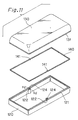
- Figure 11 shows the assembly 110 in exploded perspective view, wherein the case main body 120 and the cover 130 are plastic mouldings formed from thermoplastic resin, and 140 is a ring shaped resistance heating element formed from a nickel-chrome alloy. A rim 131 is formed on the edges of cover 130.
- the resistance heating element 140 has the same profile as the casing.
- the present embodiment uses an element material SUS 303 with thickness 0.15 mm and width 0.5 mm with two circular electrode pads 141 positioned at opposing points dividing the resistance heating element 140 into two equal sections.
- the channel section 121 in the bottom case part 120 and the relieved parts 122 of approximately same shape as the two electrode pads 141 of the resistance heating element 140 are provided on the upper rim around the sides of the case part 120.
- Figure 12 is a cross-sectional view taken along the line B-B' of Figure 11.
- the terminal guide hole 124 opens toward the bottom face of the case part 120 on the rear side of parts 122, and a small diameter hole 124 is provided toward the bottom of the main part 120 to align with the terminal guide hole 123 at the central area of 122.
- Integrally formed protrusion sections 125 are located around the periphery of hole 124 on the side of terminal guide hole 123.
- the small hole 124 may be moulded during the moulding of case 120, or may be processed or formed at a later stage.
- Figure 13 shows a view prior to fusing.
- the resistance heating element 140 is assembled into the channel 121 so that the electrode pads 141 of resistance heating element 140 may be located in the relieved parts 122 formed in the channel 121 so that the electrode pads 141 of resistance heating element 240 may be located in the relieved parts 122 formed in the channel 121, the cover 130 is then fitted with the lower rim forming the fusion face engaging the fusion face on the side of the main body 120.
- the resistance heating element 140 is trapped between the fusion faces.
- the body 120 and the cover 130 are pressed together with an adequate force using a clamp (not shown).
- two voltage applying terminals 150 connected to a voltage supply controller (not shown) are inserted into the respective terminal guide holes 123, and further brought into contact with the electrode pads 141 of heating element 140 through the small diameter hole 124, a voltage of AC 4V at about 1000A is applied for 2.5 seconds to heat the element 140.
- This heating varies according to the size of case and resin used.
- the resin is fused by the heating of the resistance heating element 140 and the fused resins on the side of body 120 and on the side of cover 130 are fused to each other.
- This fusion zone is the area enclosed by the broken lines in Figure 14.
- the voltage is cut-off when a sufficiently fused state is reached and the terminal 150 is withdrawn to allow cooling down.
- the fused resin hardens and the case main body 120 and the cover 130 are fused and connected to each other.
- a fusing tip 160 whose contact face is of cup shape is inserted into the terminal guide hole 123, and contacts the protrusion 125 around hole 124.
- the resin of protrusion 125 is melted and further pressed by the tip, so that the resin is shaped and fused.
- the part 126 formed as shown in Figure 16 blocks-off the small diameter hole 124 and the electrode pads 141 and element 140 are totally enclosed and the case 110 is hermetically sealed.
- the tip 160 may be a heating rod, but a better finish can be obtained if the deposition tip of such construction can blow a refrigerant over a metallic strip to cool it down after applying a voltage to the metallic strip for the fusing operation.
- the small diameter hole 124 is provided on the side of the main body 120 and the voltage impressing terminal 150 is forced against the electrode pads 141 of element 140 from the rear of body 120, but it is also possible to provide the hole 124 on the side of cover 130 and the position of small diameter hole 124 can be optionally elected in view of the particular shape of the case and the manufacturing process.
- the electrode pad 141 is located on the resistance heating element but this is not essential where the voltage impressing terminal can be brought into good contact with the resistance heating element itself.
- This embodiment relates to a method for contacting the voltage impressing terminal from a lateral face onto the resistance heating element located between the main body of the case and the cover.
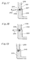
- Figures 17 to Figure 19 show cross-sectional view of the relevant part, while Figure 20 shows a complete perspective view of case 210.
- the channel 221 has an opening 228 facing the outside of the main case body 220 with an inner rib 227 and at two opposed sides of the case.
- the openings provide access to the resistance heating element 240 approximately dividing the element 240 into two parts.
- the resistance heating element 240 is seated into the channel 221 formed around the case body side wall 220 as shown in Figure 17.
- the cover 230 is then positioned and the lower rim mated with the opposed face on the main body 220, with the resistance heating element 240 trapped between the faces to be fused.
- the same procedures as those of Embodiments 1 and 2 are adopted and the case main body 220 and the cover 230 are pressed together with an adequate force using a press (not shown).
- the resistance heating element 240 is thus exposed at two opposed places through apertures 228 in the main body 220.
- the voltage impressing terminals 250 can be pressed against the sections of exposed resistance heating element 240, and voltage applied as shown in Figure 18, the resistance heating element 240 is thus heated and the fusion zone shown by the dotted lines is formed. After cooling the main body 220 and the cover 230 are fused together.
- Figure 19 shows a cross-section view of the fusion zone along the channel 221 away from apertures 228.
- Figure 20 shows a complete assembly and the position of apertures.
- the moulded piece shown in Figure 21 formed from an ABS plastic resin was used as the test piece.
- the test (1) used the trapped resistance heating element R formed from SUS 304 on one side of the test piece A, and a voltage of AC 4V (6A) was applied to the said heating element for the thermal fusion.
- the test (2) used an ultrasonic method with integrally moulded rib S whose cross-section was triangular. Both the faces were brought into contact with each other for the fusion in the test piece A.
- the units for the figures in the drawings are mm.
- the tensile direction when taking the measurement of tensile strength is shown in (3).
- the electrode for applying the voltage does not protrude from the outside of the product and there is thus no need for a secondary operation of cutting the electrode.
- the entire joint plane can be fused giving enhanced strength and enhanced sealing.
- a hermetically sealed plastic case can be manufactured by closing the small diameter holes for applying the voltage, and fusing this part after connection to block the electrode holes.
- the resistance heating element can be produced efficiently by stamping the resistance heating from thin plate.
- the junction strength between the main body and the cover can be enhanced.
Landscapes
- Engineering & Computer Science (AREA)
- Mechanical Engineering (AREA)
- Lining Or Joining Of Plastics Or The Like (AREA)
Description
- This invention relates to a method and apparatus for joining and closing a case body with a cover after assembling components such as a battery or other parts into the case body.
- In order to join a casing body and a cover both of which are formed from a thermoplastic material a connection may be made using ultrasonic fusion, high frequency electromagnetic induction fusion or by using a bonding agent or adhesive.
- Such methods using ultrasonic high frequency electromagnetic induction may damage electronic components. Connection by adhesive bonding agent may take time as the adhesive needs to harden and occasionally the bonding agent exudes out of the faces to be joined which may stain and mar the outside appearance.
- As a means for solving this problem, Japanese Unexamined Patent Publication (Kokai) No. S58-59050 and Unexamined Patent Publication (Kokai) No. S62-288029 disclose a method for trapping a heating element between the case body and the cover and fusing the thermoplastic by heating whereby the case and cover are joined. This provides an effective joint without damage to internal components and without affecting the appearance because the process is localised.
- A disadvantage is that an electrode or a resistance heating element conductor by which a supply voltage is applied to the resistance heating element protrudes outside the case and may interfere during assembly of the case into a second casing. For a case body the protruding electrodes can spoil the outside appearance and provide a hazard thus, for this reason, post-processing becomes necessary to cut off the protruding portion of the electrode and conductor.
- It is also possible for contaminants such as liquids to ingress through the electrode to plastic joint after fusion where they pass through the plastic case.
- One object of this invention is to provide a method for thermally joining a moulded plastic product formed from a thermoplastic resin using a heating element where the voltage is applied without the ends of the resistance element projecting from the body.
- Another object is to provide a method wherein the body is sealed so that the electrode does not remain exposed to form any gaps in the casing parts.
- A further object is to provide a method wherein the resistance heating element is completely sealed and embedded and where the whole of the plane of the joint is fused.
- According to this invention there is provided a method for connecting together two parts formed of thermoplastic materials using a heat fusion process, wherein an electric resistance heating element is located between the parts which are brought together under pressure after which an electric current is passed through the said element sufficient to melt the plastic and fuse the parts together at their junction,
characterised in that current applying electrodes are inserted into access apertures provided in a casing part to contact the heating element after which current is applied for the purpose of heating the element to melt and fuse the parts at their junction following which the electrodes are withdrawn from the apertures. - Further and preferred features of this invention are described in the appended sub-claims.
- This invention is described in greater detail with reference to the drawings showing embodiments by way of examples only.
- In the drawings:_
- Figure 1
- is a perspective view of a battery case using the
technique of
Embodiment 1 of this invention, - Figure 2
- is an exploded view showing the construction of Embodiment 1,
- Figure 3
- is a plan view of the main case body of
Embodiment 1 from the cover side with the resistance heating element in position, - Figure 4
- is a cross section on A-A' of Figure 2,
- Figure 5
- is a cross section on A-A' but with the parts assembled,
- Figure 6
- is a cross section on A-A'during the fusion process,
- Figure 7
- is a cross section on A-A' after fusion and before closure of the electrode hole,
- Figure 8
- is a cross section on A-A' after closure of the electrode hole,
- Figure 9
- is a cross section on A-A' after closure of the electrode hole by a plug,
- Figure 10
- is a perspective view of a battery case using the
technique of
Embodiment 2 of this invention, - Figure 11
- is an exploded view showing the construction of Embodiment 2,
- Figure 12
- is a cross section taken on B-B' of Figure 11,
- Figure 13
- is a cross-section on B-B' but with the parts assembled,
- Figure 14
- is a cross-section on B-B' during the fusion process,
- Figure 15
- is a cross-section on B-B' after fusion but before closure of the electrode hole,
- Figure 16
- is a cross-section on B-B' after closure of the electrode hole,
- Figure 17
- is a cross-section showing a
further embodiment 3 wherein the electrodes are applied from the side of the casing, - Figure 18
- shows a cross-section as in Figure 17 after heating and fusion,
- Figure 19
- shows a cross-section at another portion of the casing shown in Figure 17,
- Figure 20
- shows a perspective view of the case of
Embodiment 3 and shown in Figures 17 to 19, and - Figure 21
- shows diagrammatically a test piece and test method used in the comparative examples.
- In this invention products are moulded using a thermoplastic resin composition to form, for example, a battery case. A groove is formed on a face of the case main body part and a small diameter hole for inserting a voltage applying terminal is provided. This groove and the small diameter hole may also be formed on the side of the cover.
- A protrusion may be formed around the small diameter hole which usually is circular but may be square or rectangular.
- A nickel-chrome alloy, iron-chrome alloy, iron-nickel alloy or the like can be used to form the resistance heating element, and various shapes of single wire or multi-stranded wires, as well as plate shapes and the like may be selected.
- The resistance heating element may preferably be formed in a ring shape in order to fuse and seal the junction all around the circumference between the case main body and the cover. As a means for forming this resistance heating element into a ring shape, both the ends of a single wire rod may be connected and, for example, a thin resistance heating plate may be punched-out using a press for formation into a ring shape. The ring shape for the resistance heating element has no free ends and forms a complete fusion seal.
- In the method of this invention the resistance heating element is assembled into a groove of the main case and a cover is placed in position with mating rims with the resistance heating element trapped therebetween and pressure applied. When a voltage is applied by terminals inserted into each of two opposed small diameter holes, contact is made with the resistance heating element, and voltage is applied to heat the resistance heating element, during which plastic around the heating element is fused.
- After this, the voltage is removed and the terminals withdrawn so that cooling of the fused parts takes place and the plastic hardens. As a result, the case main body and the cover are fused together and connected.
- The result is a fully sealed and integrated case with no accessible resistance heating element.
- Figure 1 shows perspective view of a
battery case 10 according to a first embodiment. Thebattery case 10 comprises acover part 30 located on amain body part 20. - Figure 2 shows the assembly in exploded view with the
battery case 10 comprisingmain body 20 and thecover 30 which are plastic mouldings formed from a thermoplastic resin. An electricresistance heating element 40 locates between the parts. Alower lip 31 is formed on the lower edge ofcover part 30. - A
channel section 21 is located on opposed sides extending in a longitudinal direction of themain body part 20 and achannel section 22 is located at an end.Retainers 23 and arib 24 are formed for temporarily holding theresistance heating element 40 on the opposing end. - A
small diameter hole 25 is drilled through the bottom face of themain body part 20 in two locations into thechannel 22. - Figure 3 is a plan view seen from the side of
cover 30 showing theresistance heating element 40 fitted into themain body part 20. Theresistance heating element 40 is located in eachchannel 21 and in thechannel 22 as well as being fixed by theretainers 23 and therib 24. - Figure 4 shows the location for applying voltage to the
resistance heating element 40 and is a cross-sectional view taken along the line A-A' through thehole 25 shown in Figure 2. - The
small diameter hole 25 is provided at the bottom face of themain body part 20 with aprotrusion 26 integrally formed around thehole 25. This defines an electricterminal guide hole 27. The internal diameter of theterminal guide hole 27 may be larger than the diameter ofhole 25, to make it easier to insert a voltage applying terminal. - It is not necessary to provide a
protrusion 26 when thehole 25 is not closed-off. Thehole 25 may be formed when moulding thecase body part 20 or may be provided afterwards. - The thermal closure method in accordance with this invention is explained with reference to Figures 5 to 8, which are cross-sectional views taken along the line A-A' of Figure 2.
- The
resistance heating element 40 is first inserted between theretainers 23 and theribs 24 of themain body part 20 so that the element is trapped and then assembled into thechannels element 40 is thus trapped between themain body 20 and thecover 30 after placing thecover 30 thereon and inserting thelower lip 31 into thechannels - The
main body part 20 and thecover 30 are pressed together with sufficient force using a pressing device (not shown). Figure 5 shows the final position. - As shown in Figure 6, two
voltage applying terminals 50 connected to a voltage supply controller (not shown) are inserted into the terminal holes 27 respectively and further pass through thesmall diameter hole 25 to contact theresistance heating element 40, after which power is applied to heat theelement 40. Because of factors such as the type of plastic resin used and the size of the case as well as the material and dimensions of theelement 40, the heating parameters are predetermined by the voltage supply controller. - The plastic around the periphery of the case is melted and fused by the heating action of the
element 40. Thus the resin along the sides ofcase body 20 and on the sides ofcover 30 are fused, this fusion area being indicated by the broken lines in Figure 6. If the voltage application is stopped when the resin is sufficiently fused and theterminals 50 are removed, then the fused plastics hardens and thecase body part 20 and thecover part 30 are connected together. - In the present embodiment, the
channel sections resistance heating element 40 are overlapped or a ring shapedresistance heating element 40 is used. - Further, the following technique may be used for sealing and concealing the
resistance heating element 40 from the outside of thecase part 10. Figure 7, Figure 8 and Figure 9 show the arrangement. - The
tip 60 of a disc shaped contact face is pressed against the tip of theprotrusion 26 as shown in Figure 7. Then, the resin of theprotrusion 26 is melted or fused, and if necessary further pressed to be collapsed by thetip 60, the resin of the fusedprotrusion 26 is formed into a homogeneous body. - When the
tip 60 is separated and cooled down, thepart 28 is formed as shown in Figure 8, and as a result, thesmall diameter hole 26 is blocked, and theresistance heating element 40 is closed-off. Thetip 60 may include a heating element. - Figure 9 shows an embodiment where a
plug body 70 is fitted in thesmall diameter hole 25 to block thesmall diameter hole 25. - The
tip 60 may be a heating rod, but a better finish can be obtained by using the tip of a refrigerant cooled metal strip for cooling-down after electrically heating the metallic strip. - The contact face shape of
tip 60 can be formed as required to produce a cup shape, a square shape or the like. - Although the
channel 21 andsmall diameter hole 25 for fitting and heating theelement 40 are provided installed on the side of casemain body 20 in this embodiment, they may also be provided on the side ofcover 30, and the position can be optionally selected for convenience of the case shape and the manufacturing process. - The embodiment described relates to a thermal production method and the assembly of the resistance heating element into the moulded product which is to be thermally connected by inserting the voltage applying terminal through the small diameter hole provided in the moulded product, to make contact with the resistance heating element for the heating and fusion process. Advantages are:
- 1) Because the electrode for applying the voltage does not protrude from the moulded product, there is no need for further processing such as the cutting of the electrode after fusion.
- 2) By fusing then closing off the small diameter hole, the heating element cannot be accessed from the outside, and liquid cannot invade. The unit is thus fully sealed and protected.
- 3) Because the small diameter hole is moulded into the product, no operation other than assembly and contacting of the resistance heating element is needed.
- 4) When reopening of the case is required, insert the electrode through the (unplugged) small diameter hole, apply a voltage to the resistance heating element and separate and release the case main body and the cover while softened and replace of repair the parts contained therein, and re-close.
-
- This embodiment uses a form of resistance heating element shaped into a ring so as not to leave any unfused portions of the case. Reference is made to Figures 10 through to Figure 16.
- Figure 10 shows a perspective view of a
battery case 110 where the case main body and the cover are joined using a ring shaped resistance heating element according to this invention. The battery case is of the shape where thecover 130 is placed on the casemain body 120. - Figure 11 shows the
assembly 110 in exploded perspective view, wherein the casemain body 120 and thecover 130 are plastic mouldings formed from thermoplastic resin, and 140 is a ring shaped resistance heating element formed from a nickel-chrome alloy. Arim 131 is formed on the edges ofcover 130. - The
resistance heating element 140 has the same profile as the casing. The present embodiment uses an element material SUS 303 with thickness 0.15 mm and width 0.5 mm with twocircular electrode pads 141 positioned at opposing points dividing theresistance heating element 140 into two equal sections. - The
channel section 121 in thebottom case part 120 and therelieved parts 122 of approximately same shape as the twoelectrode pads 141 of theresistance heating element 140 are provided on the upper rim around the sides of thecase part 120. - Figure 12 is a cross-sectional view taken along the line B-B' of Figure 11. The
terminal guide hole 124 opens toward the bottom face of thecase part 120 on the rear side ofparts 122, and asmall diameter hole 124 is provided toward the bottom of themain part 120 to align with theterminal guide hole 123 at the central area of 122. Integrally formedprotrusion sections 125 are located around the periphery ofhole 124 on the side ofterminal guide hole 123. Thesmall hole 124 may be moulded during the moulding ofcase 120, or may be processed or formed at a later stage. - The assembly of the resistance heating element is explained with reference to Figures 13 to Figure 16 which are the enlarged cross-section views taken along the line B-B' of Figure 11.
- Figure 13 shows a view prior to fusing. The
resistance heating element 140 is assembled into thechannel 121 so that theelectrode pads 141 ofresistance heating element 140 may be located in therelieved parts 122 formed in thechannel 121 so that theelectrode pads 141 ofresistance heating element 240 may be located in therelieved parts 122 formed in thechannel 121, thecover 130 is then fitted with the lower rim forming the fusion face engaging the fusion face on the side of themain body 120. Theresistance heating element 140 is trapped between the fusion faces. Thebody 120 and thecover 130 are pressed together with an adequate force using a clamp (not shown). - Next, as shown in Figure 14, two
voltage applying terminals 150 connected to a voltage supply controller (not shown) are inserted into the respective terminal guide holes 123, and further brought into contact with theelectrode pads 141 ofheating element 140 through thesmall diameter hole 124, a voltage of AC 4V at about 1000A is applied for 2.5 seconds to heat theelement 140. This heating varies according to the size of case and resin used. - The resin is fused by the heating of the
resistance heating element 140 and the fused resins on the side ofbody 120 and on the side ofcover 130 are fused to each other. This fusion zone is the area enclosed by the broken lines in Figure 14. The voltage is cut-off when a sufficiently fused state is reached and the terminal 150 is withdrawn to allow cooling down. The fused resin hardens and the casemain body 120 and thecover 130 are fused and connected to each other. - The following technique may be included if the
resistance heating element 140 is to be sealed from the outside ofcase 120 in order to hermetically seal thecase 110. Figure 15 and Figure 16 show this technique. - As shown in Figure 15, a
fusing tip 160 whose contact face is of cup shape is inserted into theterminal guide hole 123, and contacts theprotrusion 125 aroundhole 124. The resin ofprotrusion 125 is melted and further pressed by the tip, so that the resin is shaped and fused. When thetip 160 is removed and cooled down, thepart 126 formed as shown in Figure 16 blocks-off thesmall diameter hole 124 and theelectrode pads 141 andelement 140 are totally enclosed and thecase 110 is hermetically sealed. - The
tip 160 may be a heating rod, but a better finish can be obtained if the deposition tip of such construction can blow a refrigerant over a metallic strip to cool it down after applying a voltage to the metallic strip for the fusing operation. - In this embodiment, the
small diameter hole 124 is provided on the side of themain body 120 and thevoltage impressing terminal 150 is forced against theelectrode pads 141 ofelement 140 from the rear ofbody 120, but it is also possible to provide thehole 124 on the side ofcover 130 and the position ofsmall diameter hole 124 can be optionally elected in view of the particular shape of the case and the manufacturing process. - The
electrode pad 141 is located on the resistance heating element but this is not essential where the voltage impressing terminal can be brought into good contact with the resistance heating element itself. - This embodiment relates to a method for contacting the voltage impressing terminal from a lateral face onto the resistance heating element located between the main body of the case and the cover.
- Figures 17 to Figure 19 show cross-sectional view of the relevant part, while Figure 20 shows a complete perspective view of
case 210. - The
channel 221 has anopening 228 facing the outside of themain case body 220 with aninner rib 227 and at two opposed sides of the case. The openings provide access to theresistance heating element 240 approximately dividing theelement 240 into two parts. - For the fused connection the
resistance heating element 240 is seated into thechannel 221 formed around the casebody side wall 220 as shown in Figure 17. Thecover 230 is then positioned and the lower rim mated with the opposed face on themain body 220, with theresistance heating element 240 trapped between the faces to be fused. The same procedures as those ofEmbodiments main body 220 and thecover 230 are pressed together with an adequate force using a press (not shown). Theresistance heating element 240 is thus exposed at two opposed places throughapertures 228 in themain body 220. Thevoltage impressing terminals 250 can be pressed against the sections of exposedresistance heating element 240, and voltage applied as shown in Figure 18, theresistance heating element 240 is thus heated and the fusion zone shown by the dotted lines is formed. After cooling themain body 220 and thecover 230 are fused together. - Figure 19 shows a cross-section view of the fusion zone along the
channel 221 away fromapertures 228. Figure 20 shows a complete assembly and the position of apertures. - The tensile strength of an ultrasonic fusion method which is customary in the art of joining thermoplastic resin was compared with the method of this invention shown in
Embodiment 2. - Table 1 indicates the result.
- The moulded piece shown in Figure 21 formed from an ABS plastic resin was used as the test piece.
- Referring to this Fig 21 the test (1) used the trapped resistance heating element R formed from SUS 304 on one side of the test piece A, and a voltage of AC 4V (6A) was applied to the said heating element for the thermal fusion.
- The test (2) used an ultrasonic method with integrally moulded rib S whose cross-section was triangular. Both the faces were brought into contact with each other for the fusion in the test piece A. The units for the figures in the drawings are mm.
- The tensile direction when taking the measurement of tensile strength is shown in (3).
- The measured results showed approximately the same tensile strength for both cases.
- Therefore, it can be said that in this invention wherein the deposition can be made instantaneously and safely using the resistance heating element is superior to the supersonic wave deposition method which involves a risk of inducing defective joints and risk to any incorporated electronic parts and the like.
Tensile strength tester: Manufactured by Toyo PrecisionDevice Fabrication Co. Ltd. Universal Tensile Tester Model V10-C Material of test piece (A) : ABS plastic resin Bonding Method Employed Sample No. Tensile Strength of Unit Area Resistance heating element 1. 22.05 N/mm2 Resistance heating element 2. 22.44 Resistance heating element 3. 23.32 Ultrasonic bonding process 4. 19.99 Ultrasonic bonding process 5. 20.29 Ultrasonic bonding process 6. 20.97 - According to the embodiments, using the ring shaped resistance heating element in the moulded casing, the following advantages occur:
- The electrode for applying the voltage does not protrude from the outside of the product and there is thus no need for a secondary operation of cutting the electrode.
- Where the resistance heating element is of ring shape, the entire joint plane can be fused giving enhanced strength and enhanced sealing.
- A hermetically sealed plastic case can be manufactured by closing the small diameter holes for applying the voltage, and fusing this part after connection to block the electrode holes.
- The resistance heating element can be produced efficiently by stamping the resistance heating from thin plate.
- If an optional concave section or ridge on the surface of resistance heating element is provided, the junction strength between the main body and the cover can be enhanced.
Claims (18)
- A method for connecting together two parts (20,30) formed of thermoplastic materials using a heat fusion process, wherein an electric resistance heating element (40) is located between the parts which are brought together under pressure after which an electric current is passed through the said element sufficient to melt the plastic and fuse the parts together at their junction, characterised in that current applying electrodes (50) are inserted into access apertures (25) provided in a casing part to contact the heating element (40) after which current is applied for the purpose of heating the element to melt and fuse the parts at their junction following which the electrodes are withdrawn from the apertures.
- A method in accordance with Claim 1, characterised in that the access apertures (25) are closed-off after withdrawal of the electrodes (50) by melting, pressing and collapsing the plastic material (26) around the apertures.
- A method in accordance with Claim 1, characterised in that the access apertures (25) are closed-off after withdrawal of the electrodes by inserting plugs (70).
- A method in accordance with any preceding Claim, characterised in that the parts (20,30) form a casing (10) having a body (20) and a lid (30) with a rim (31) which engages a channel (21) in the body (20), the heating element (40) being provided in the channel (21), the heating element (40) being pre-assembled into the channel (21) which has the externally accessible apertures (25), following which components are located in the body, if required, the lid rim (31) being then engaged with the channel (21) and the electrodes (50) thereafter inserted through the apertures (25) to apply current to the heating element.
- A method in accordance with any preceding Claim, characterised in that the access apertures (25) are located adjacently in the casing the heating element (40) comprising a loop with the ends brought together for contact by an electrode (50) adjacent a respective aperture.
- A method in accordance with any preceding Claim 1 to 4, characterised in that the access apertures (124) are located one on each opposite side of the casing (121), the heating element (140) comprising a continuous loop with opposed contact pads (141) accessible through respective apertures.
- A method in accordance with any preceding Claim, characterised in that the current applying electrodes comprise probes (50) inserted through the access apertures (25) from the outside to contact the element (40) lying in the plane of the junction between the two parts.
- A method in accordance with any preceding Claim, characterised in that the access apertures (25) are formed in the casing by a drilling operation after which the electrodes (50) are inserted.
- A moulded product, especially a two-part casing for housing components such as electrical batteries, and comprising two parts (20,30) formed of thermoplastic materials and which are joined together using a heat fusion process, wherein an electric resistance heating element (40) is located between the parts which are brought together under pressure after which an electric current is passed through the said element sufficient to melt the plastic and fuse the parts together at their junction, characterised in that externally opening current applying electrode access apertures (25) are provided in one casing part (20) through which contact may be made between the internally located heating element (40) and the electrodes.
- A moulded product as claimed in Claim 9, characterised in that the heating element is located in a channel (21,22,121,221) of one casing part (20, 120, 220) the access apertures (25, 124, 228) being provided through the wall of a casing part to expose a portion of the heating element.
- A moulded product in accordance with Claim 9 or 10, characterised in that the heating element comprises a wire (40) formed into a discontinuous loop, each end of the wire being adjacent but spaced and aligned with an aperture (25) such that a current applying probe (50) passed through the aperture (25) may electrically contact respective ends of the wire loop (40).
- A moulded product according to Claim 9 or 10, characterised in that the element (140) is of ring shape, the apertures (124) being provided at diametrically opposed locations in the casing (120) such that current applying probes (150) passed through the apertures may electrically contact respective opposed sides (141) of the element (140).
- A moulded product according to any preceding Claim 9 to 12, characterised by a plurality of electrode access apertures (25, 124, 228) extending through one or other or both casing parts (20, 30, 120, 130, 220, 230).
- A moulded product according to any preceding Claim 9 to 13, characterised in that the heating element is formed from a thin plate (140) by a stamping operation, the parts of the element adapted to be contacted by the electrodes comprising contact pads (141) each located adjacent an access aperture (124).
- A moulded product according to any preceding Claim 9 to 14, characterised in that the product comprises a lower casing (20, 120, 220) with an upstanding wall having a channel (21, 122, 221) receiving the element (40, 140, 240) and a top cover (30, 130, 230) having a rim to engage the channel, the element comprising a planar ring (40, 140) lying on the plane of the junction between the casing and cover, the parts at the junction being fusible on application of heating current to the element.
- A moulded product according to an one of Claims 9 to 15, characterised in that the access apertures (25, 124, 228) have an outwardly extending boss of enlarged diameter (26, 125, 228) which is adapted to be melted and collapsed to close the aperture or which is adapted to receive a plug (70) to close the aperture.
- A moulded product according to any preceding claim 9 to 16, characterised in that the apertures (228) are provided in the sides of the casing (220).
- A moulded product in accordance with any preceding Claim 9 to 17, characterised in the casing houses a battery unit.
Applications Claiming Priority (6)
| Application Number | Priority Date | Filing Date | Title |
|---|---|---|---|
| JP209647/96 | 1996-08-08 | ||
| JP8209647A JP2937311B2 (en) | 1996-08-08 | 1996-08-08 | Thermoplastic welding method |
| JP20964796 | 1996-08-08 | ||
| JP280435/96 | 1996-10-23 | ||
| JP28043596 | 1996-10-23 | ||
| JP28043596A JP2856352B2 (en) | 1996-10-23 | 1996-10-23 | Method for heat welding molded articles molded with thermoplastic resin and molded articles for heat welding |
Publications (2)
| Publication Number | Publication Date |
|---|---|
| EP0823321A1 EP0823321A1 (en) | 1998-02-11 |
| EP0823321B1 true EP0823321B1 (en) | 2001-06-13 |
Family
ID=26517578
Family Applications (1)
| Application Number | Title | Priority Date | Filing Date |
|---|---|---|---|
| EP19970306022 Expired - Lifetime EP0823321B1 (en) | 1996-08-08 | 1997-08-07 | Joining thermoplastic cases and covers by fusion |
Country Status (3)
| Country | Link |
|---|---|
| US (1) | US5968442A (en) |
| EP (1) | EP0823321B1 (en) |
| DE (1) | DE69705174T2 (en) |
Cited By (1)
| Publication number | Priority date | Publication date | Assignee | Title |
|---|---|---|---|---|
| DE102018114801A1 (en) | 2018-06-20 | 2019-12-24 | Biotronik Se & Co. Kg | Diffusion barrier for implantable electrode lines |
Families Citing this family (19)
| Publication number | Priority date | Publication date | Assignee | Title |
|---|---|---|---|---|
| JPH11154208A (en) * | 1997-11-21 | 1999-06-08 | Mitsubishi Electric Corp | IC card and manufacturing method thereof |
| JP3394193B2 (en) * | 1998-09-01 | 2003-04-07 | ジー・ピー・ダイキョー株式会社 | Method of joining thermoplastic resin molded products |
| JP2895475B1 (en) * | 1998-05-15 | 1999-05-24 | 東北ムネカタ株式会社 | Method for welding molded article molded with thermoplastic resin and welding electrode used in this welding method |
| DE19916494A1 (en) * | 1999-04-13 | 2000-10-19 | Mannesmann Vdo Ag | Method for producing a plastic component and fuel tank for a motor vehicle |
| EP1097797B1 (en) * | 1999-11-02 | 2004-02-04 | TOHOKU MUNEKATA Co., Ltd. | Joining thermoplastic cases and covers by fusion |
| AU2002216635A1 (en) * | 2000-10-18 | 2002-04-29 | Honeywell International, Inc. | Modular entertainment and data system |
| US6838617B2 (en) * | 2003-05-01 | 2005-01-04 | Ultratech International, Inc. | Macroencapsulation container having both releasable and permanent sealing means |
| US7389789B2 (en) * | 2004-01-21 | 2008-06-24 | Raval-Agriculture Cooperative Societies Ltd. | Fuel accessory for fuel tank and method for internally attaching same |
| US7913712B2 (en) * | 2004-01-21 | 2011-03-29 | Raval A.C.S. Ltd. | Fuel accessory for fuel tank and method for internally attaching same |
| KR20080031466A (en) * | 2005-07-27 | 2008-04-08 | 어플라이드 머티어리얼스, 인코포레이티드 | Hot wire welding method of plastic |
| JP5043021B2 (en) | 2005-10-04 | 2012-10-10 | アプライド マテリアルズ インコーポレイテッド | Method and apparatus for drying a substrate |
| US8741091B2 (en) | 2012-04-26 | 2014-06-03 | Richard Hardy | Method for thermoplastic welding and welded composite structures |
| CN103612394B (en) * | 2013-11-29 | 2015-07-15 | 北京化工大学 | High-voltage static drive and variable-diameter 3D (three dimensional) printer |
| DE102015110244B4 (en) | 2015-06-25 | 2023-01-19 | Schuler Pressen Gmbh | Battery cell housing and method of manufacturing same |
| GB2561234B (en) | 2017-04-07 | 2019-07-24 | Ford Motor Co | A housing assembly and method |
| US10688731B2 (en) * | 2018-01-30 | 2020-06-23 | Te Connectivity Corporation | System and method for bonding structural components |
| CN109822919A (en) * | 2019-01-31 | 2019-05-31 | 诸暨市逍遥管道科技有限公司 | During accurate control electric fusion welding on electric melting pipe fittings weldingvoltage welding method |
| KR102722506B1 (en) * | 2020-07-24 | 2024-10-29 | 에스케이온 주식회사 | Battery module with double fixing structure and manufacturing method thereof |
| DE102023100401A1 (en) | 2023-01-10 | 2024-07-11 | Ford Global Technologies, Llc | Battery assembly and method for manufacturing a battery assembly |
Family Cites Families (8)
| Publication number | Priority date | Publication date | Assignee | Title |
|---|---|---|---|---|
| NL236188A (en) * | 1958-02-17 | |||
| FR1372303A (en) * | 1963-10-22 | 1964-09-11 | Rollmaplast Ag | Welding sleeve for plastics and method of making this sleeve |
| FR1427108A (en) * | 1964-12-10 | 1966-04-20 | Citroen Sa Andre | Method of manufacturing a steering wheel and steering wheel thus obtained |
| JPS5859050A (en) * | 1981-10-05 | 1983-04-07 | Hiroshima Plast Kk | Welding method for resin |
| SU1070812A1 (en) * | 1982-09-03 | 1991-07-23 | Киевский филиал Всесоюзного научно-исследовательского института по монтажным и специальным строительным работам | Coupling for welding thermoplastic tubes |
| US4743320A (en) * | 1984-08-07 | 1988-05-10 | Bondico, Inc. | Method of heat sealing a thermoplastic drum and lid and article of manufacture |
| JPS62288029A (en) * | 1986-06-06 | 1987-12-14 | Aisin Seiki Co Ltd | Vessel made of resin and bonded by fusion, and fusion bonding thereof |
| JP2813148B2 (en) * | 1994-03-02 | 1998-10-22 | 日本碍子株式会社 | Ceramic products |
-
1997
- 1997-06-23 US US08/880,617 patent/US5968442A/en not_active Expired - Fee Related
- 1997-08-07 EP EP19970306022 patent/EP0823321B1/en not_active Expired - Lifetime
- 1997-08-07 DE DE69705174T patent/DE69705174T2/en not_active Expired - Fee Related
Cited By (2)
| Publication number | Priority date | Publication date | Assignee | Title |
|---|---|---|---|---|
| DE102018114801A1 (en) | 2018-06-20 | 2019-12-24 | Biotronik Se & Co. Kg | Diffusion barrier for implantable electrode lines |
| US11610703B2 (en) | 2018-06-20 | 2023-03-21 | Biotronik Se & Co. Kg | Diffusion barrier for implantable electrode leads |
Also Published As
| Publication number | Publication date |
|---|---|
| EP0823321A1 (en) | 1998-02-11 |
| DE69705174T2 (en) | 2002-05-02 |
| US5968442A (en) | 1999-10-19 |
| DE69705174D1 (en) | 2001-07-19 |
Similar Documents
| Publication | Publication Date | Title |
|---|---|---|
| EP0823321A1 (en) | Joining thermoplastic cases and covers by fusion | |
| EP0420413B1 (en) | Means and method of securing an insert in a shell | |
| CA2238921C (en) | Connection structure of wire and terminal, connecting method therefor and a terminal | |
| JP3311645B2 (en) | How to connect wires and terminals | |
| US6072124A (en) | Waterproof covered wire connection | |
| JP4396787B2 (en) | Thin temperature fuse and method of manufacturing thin temperature fuse | |
| US8785252B2 (en) | Resin sealed semiconductor device and manufacturing method therefor | |
| JPH09320652A (en) | Insulated wire joint structure | |
| JPH1055869A (en) | Method of joining covered electric wires and joining structure of covered electric wires | |
| EP0849834B1 (en) | Connection structure and method for electric wire and terminal | |
| US6195885B1 (en) | Method of making wire connecting structure | |
| GB2321795A (en) | Ultrasonic cable connection | |
| US5947073A (en) | Adhesively bonded plastic automotive air intake assembly | |
| JPH117986A (en) | Connection structure between wires and terminals | |
| EP1097797B1 (en) | Joining thermoplastic cases and covers by fusion | |
| KR19980032460A (en) | Cladding wire bonding method and structure | |
| JP3311627B2 (en) | Wire connection structure | |
| JP2856352B2 (en) | Method for heat welding molded articles molded with thermoplastic resin and molded articles for heat welding | |
| JP2003191341A (en) | Thermal welding method for thermoplastic resin molded products | |
| US4220938A (en) | Thermostatic electrical switch | |
| JP3053786B2 (en) | Heat welding method of sealed resin case | |
| GB2321791A (en) | Ultrasonic cable connection | |
| JP3523065B2 (en) | Connection structure and connection method between wire and terminal, and terminal | |
| GB2119179A (en) | Cooling a terminal of a plug | |
| RU2214654C2 (en) | Storage battery sealing method |
Legal Events
| Date | Code | Title | Description |
|---|---|---|---|
| PUAI | Public reference made under article 153(3) epc to a published international application that has entered the european phase |
Free format text: ORIGINAL CODE: 0009012 |
|
| AK | Designated contracting states |
Kind code of ref document: A1 Designated state(s): DE GB IE NL SE |
|
| 17P | Request for examination filed |
Effective date: 19980427 |
|
| AKX | Designation fees paid |
Free format text: DE GB IE NL SE |
|
| RBV | Designated contracting states (corrected) |
Designated state(s): DE GB IE NL SE |
|
| GRAG | Despatch of communication of intention to grant |
Free format text: ORIGINAL CODE: EPIDOS AGRA |
|
| GRAG | Despatch of communication of intention to grant |
Free format text: ORIGINAL CODE: EPIDOS AGRA |
|
| GRAH | Despatch of communication of intention to grant a patent |
Free format text: ORIGINAL CODE: EPIDOS IGRA |
|
| 17Q | First examination report despatched |
Effective date: 20001020 |
|
| GRAH | Despatch of communication of intention to grant a patent |
Free format text: ORIGINAL CODE: EPIDOS IGRA |
|
| GRAA | (expected) grant |
Free format text: ORIGINAL CODE: 0009210 |
|
| AK | Designated contracting states |
Kind code of ref document: B1 Designated state(s): DE GB IE NL SE |
|
| PG25 | Lapsed in a contracting state [announced via postgrant information from national office to epo] |
Ref country code: NL Free format text: LAPSE BECAUSE OF FAILURE TO SUBMIT A TRANSLATION OF THE DESCRIPTION OR TO PAY THE FEE WITHIN THE PRESCRIBED TIME-LIMIT Effective date: 20010613 |
|
| REF | Corresponds to: |
Ref document number: 69705174 Country of ref document: DE Date of ref document: 20010719 |
|
| PG25 | Lapsed in a contracting state [announced via postgrant information from national office to epo] |
Ref country code: IE Free format text: LAPSE BECAUSE OF NON-PAYMENT OF DUE FEES Effective date: 20010807 |
|
| REG | Reference to a national code |
Ref country code: IE Ref legal event code: FG4D |
|
| NLV1 | Nl: lapsed or annulled due to failure to fulfill the requirements of art. 29p and 29m of the patents act | ||
| REG | Reference to a national code |
Ref country code: GB Ref legal event code: IF02 |
|
| PLBE | No opposition filed within time limit |
Free format text: ORIGINAL CODE: 0009261 |
|
| STAA | Information on the status of an ep patent application or granted ep patent |
Free format text: STATUS: NO OPPOSITION FILED WITHIN TIME LIMIT |
|
| 26N | No opposition filed | ||
| REG | Reference to a national code |
Ref country code: IE Ref legal event code: MM4A |
|
| PGFP | Annual fee paid to national office [announced via postgrant information from national office to epo] |
Ref country code: GB Payment date: 20080818 Year of fee payment: 12 |
|
| PGFP | Annual fee paid to national office [announced via postgrant information from national office to epo] |
Ref country code: SE Payment date: 20080825 Year of fee payment: 12 |
|
| PGFP | Annual fee paid to national office [announced via postgrant information from national office to epo] |
Ref country code: DE Payment date: 20081113 Year of fee payment: 12 |
|
| GBPC | Gb: european patent ceased through non-payment of renewal fee |
Effective date: 20090807 |
|
| PG25 | Lapsed in a contracting state [announced via postgrant information from national office to epo] |
Ref country code: DE Free format text: LAPSE BECAUSE OF NON-PAYMENT OF DUE FEES Effective date: 20100302 |
|
| PG25 | Lapsed in a contracting state [announced via postgrant information from national office to epo] |
Ref country code: GB Free format text: LAPSE BECAUSE OF NON-PAYMENT OF DUE FEES Effective date: 20090807 |
|
| PG25 | Lapsed in a contracting state [announced via postgrant information from national office to epo] |
Ref country code: SE Free format text: LAPSE BECAUSE OF NON-PAYMENT OF DUE FEES Effective date: 20090808 |