EP0822887B1 - Machine for producing a board- or panel-shaped wooden element - Google Patents
Machine for producing a board- or panel-shaped wooden element Download PDFInfo
- Publication number
- EP0822887B1 EP0822887B1 EP96912356A EP96912356A EP0822887B1 EP 0822887 B1 EP0822887 B1 EP 0822887B1 EP 96912356 A EP96912356 A EP 96912356A EP 96912356 A EP96912356 A EP 96912356A EP 0822887 B1 EP0822887 B1 EP 0822887B1
- Authority
- EP
- European Patent Office
- Prior art keywords
- carriage
- material web
- rows
- machine
- cutting
- Prior art date
- Legal status (The legal status is an assumption and is not a legal conclusion. Google has not performed a legal analysis and makes no representation as to the accuracy of the status listed.)
- Expired - Lifetime
Links
Images



Classifications
-
- B—PERFORMING OPERATIONS; TRANSPORTING
- B27—WORKING OR PRESERVING WOOD OR SIMILAR MATERIAL; NAILING OR STAPLING MACHINES IN GENERAL
- B27M—WORKING OF WOOD NOT PROVIDED FOR IN SUBCLASSES B27B - B27L; MANUFACTURE OF SPECIFIC WOODEN ARTICLES
- B27M3/00—Manufacture or reconditioning of specific semi-finished or finished articles
- B27M3/0013—Manufacture or reconditioning of specific semi-finished or finished articles of composite or compound articles
- B27M3/006—Manufacture or reconditioning of specific semi-finished or finished articles of composite or compound articles characterised by oblong elements connected both laterally and at their ends
-
- B—PERFORMING OPERATIONS; TRANSPORTING
- B26—HAND CUTTING TOOLS; CUTTING; SEVERING
- B26D—CUTTING; DETAILS COMMON TO MACHINES FOR PERFORATING, PUNCHING, CUTTING-OUT, STAMPING-OUT OR SEVERING
- B26D1/00—Cutting through work characterised by the nature or movement of the cutting member or particular materials not otherwise provided for; Apparatus or machines therefor; Cutting members therefor
- B26D1/56—Cutting through work characterised by the nature or movement of the cutting member or particular materials not otherwise provided for; Apparatus or machines therefor; Cutting members therefor involving a cutting member which travels with the work otherwise than in the direction of the cut, i.e. flying cutter
- B26D1/60—Cutting through work characterised by the nature or movement of the cutting member or particular materials not otherwise provided for; Apparatus or machines therefor; Cutting members therefor involving a cutting member which travels with the work otherwise than in the direction of the cut, i.e. flying cutter and is mounted on a movable carriage
- B26D1/605—Cutting through work characterised by the nature or movement of the cutting member or particular materials not otherwise provided for; Apparatus or machines therefor; Cutting members therefor involving a cutting member which travels with the work otherwise than in the direction of the cut, i.e. flying cutter and is mounted on a movable carriage for thin material, e.g. for sheets, strips or the like
-
- B—PERFORMING OPERATIONS; TRANSPORTING
- B27—WORKING OR PRESERVING WOOD OR SIMILAR MATERIAL; NAILING OR STAPLING MACHINES IN GENERAL
- B27M—WORKING OF WOOD NOT PROVIDED FOR IN SUBCLASSES B27B - B27L; MANUFACTURE OF SPECIFIC WOODEN ARTICLES
- B27M1/00—Working of wood not provided for in subclasses B27B - B27L, e.g. by stretching
- B27M1/08—Working of wood not provided for in subclasses B27B - B27L, e.g. by stretching by multi-step processes
-
- Y—GENERAL TAGGING OF NEW TECHNOLOGICAL DEVELOPMENTS; GENERAL TAGGING OF CROSS-SECTIONAL TECHNOLOGIES SPANNING OVER SEVERAL SECTIONS OF THE IPC; TECHNICAL SUBJECTS COVERED BY FORMER USPC CROSS-REFERENCE ART COLLECTIONS [XRACs] AND DIGESTS
- Y10—TECHNICAL SUBJECTS COVERED BY FORMER USPC
- Y10T—TECHNICAL SUBJECTS COVERED BY FORMER US CLASSIFICATION
- Y10T156/00—Adhesive bonding and miscellaneous chemical manufacture
- Y10T156/12—Surface bonding means and/or assembly means with cutting, punching, piercing, severing or tearing
-
- Y—GENERAL TAGGING OF NEW TECHNOLOGICAL DEVELOPMENTS; GENERAL TAGGING OF CROSS-SECTIONAL TECHNOLOGIES SPANNING OVER SEVERAL SECTIONS OF THE IPC; TECHNICAL SUBJECTS COVERED BY FORMER USPC CROSS-REFERENCE ART COLLECTIONS [XRACs] AND DIGESTS
- Y10—TECHNICAL SUBJECTS COVERED BY FORMER USPC
- Y10T—TECHNICAL SUBJECTS COVERED BY FORMER US CLASSIFICATION
- Y10T156/00—Adhesive bonding and miscellaneous chemical manufacture
- Y10T156/12—Surface bonding means and/or assembly means with cutting, punching, piercing, severing or tearing
- Y10T156/1374—Surface bonding means and/or assembly means with cutting, punching, piercing, severing or tearing with means projecting fluid against work
-
- Y—GENERAL TAGGING OF NEW TECHNOLOGICAL DEVELOPMENTS; GENERAL TAGGING OF CROSS-SECTIONAL TECHNOLOGIES SPANNING OVER SEVERAL SECTIONS OF THE IPC; TECHNICAL SUBJECTS COVERED BY FORMER USPC CROSS-REFERENCE ART COLLECTIONS [XRACs] AND DIGESTS
- Y10—TECHNICAL SUBJECTS COVERED BY FORMER USPC
- Y10T—TECHNICAL SUBJECTS COVERED BY FORMER US CLASSIFICATION
- Y10T156/00—Adhesive bonding and miscellaneous chemical manufacture
- Y10T156/17—Surface bonding means and/or assemblymeans with work feeding or handling means
- Y10T156/1702—For plural parts or plural areas of single part
- Y10T156/1712—Indefinite or running length work
- Y10T156/1715—Means joining indefinite length work edge to edge
- Y10T156/1717—Means applying adhesively secured tape to seam
Definitions
- the present invention relates to a machine for producing a board- or panel-shaped wooden element which consists of at least two parallel rows of bars and which is especially intended to be glued to at least one other board- or panel-shaped wooden element, thereby to form a building element for the production of a laminated wooden floor, such as a parquet floor.
- the object of this invention is to provide a continuously operating machine for implementing the last-mentioned method.
- this object is achieved by a machine which is characterised in that it has a feeding path for continuously feeding at least two adjacent rows of adjoining bars, a tape-applying device for applying a strip of adhesive tape on each pair of adjacent rows in parallel with these in such a manner that the strip of adhesive tape covers the joint between said rows in order to join the rows together, and a cutting device for cutting the continuous material web made up of the joined bar rows into predetermined lengths, said cutting device having a carriage which is reciprocatingly movable along the feeding path between a rear initial position and a front turning position, a cutting unit mounted on the rear portion of the carriage, and a stop means mounted on the front portion of the carriage, the distance between the cutting unit and the stop means being adjustable according to the aimed-at cutting length, that the stop means in the initial position of the carriage is so placed in relation to the feeding path that the material web will, during the feeding operation, come to be applied against the stop means with its front end so as to displace the carriage from its initial position to its turning position, that the stop means in the
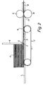
- the illustrated machine At its inlet end (Fig. 2), the illustrated machine has a feeding table 1 and a feeding conveyor 2, which is in the form of an endless conveyor belt having a horizontal upper run 3. Two juxtaposed stacks 4 of wooden bars 5 rest on the upper run 3 of the conveyor belt and are driven thereby in their longitudinal direction towards a stop 6. Between the stop 6, which is vertically adjustable, and the upper run 3, there is provided a feeding gap 7 which is adjustable by vertical adjustment of the stop and whose height only slightly exceeds the thickness of the bars 5, thus enabling the feeding of but one bar 5 at a time (the lowermost) from each stack 4.
- the feeding conveyor 2 is followed by a feeding path extending along the machine and being in the form of a slide table 8.
- the bars 5 fed from each stack 4 form a bar row, which is transferred onto the slide table 8.
- the two bar rows are pressed against one another with the aid of guiding rules (not shown) arranged along the sides of the slide table 8.
- Two pairs of rubber-clad cylinders 9, 10 and 11, 12 arranged in succession drive the two bar rows forward along the slide table 8.
- the lowermost cylinder 10, 12 of each pair of cylinders is placed in a recess 13 (Fig. 2) in the slide table 8.
- the uppermost cylinder 9, 11 of each pair of cylinders is rotated with the aid of a motor (not shown).
- the cylinders 9, 10 and 11, 12 of each pair of cylinders form a feeding nip, through which pass the two bar rows.
- the uppermost cylinder 9 of the cylinder pair 9, 10 located upstream is driven at a slightly higher peripheral speed than is the uppermost cylinder 11 of the cylinder pair 11, 12 located downstream.
- a metal sheet 14 is arranged above the slide table 8 in order to prevent the bars 5 in the two rows from rising at their edges when pressed against one another in the lateral as well as the longitudinal direction.
- a rubber-clad tape-application cylinder 15 which is freely rotatable, is disposed after the two cylinder pairs 9, 10 and 11, 12. The cylinder 15 is pressed against the bar rows with the aid of a cylinder assembly (not shown).
- a strip of adhesive tape 16 is unwound from a roller 17 provided above the slide table 8 and is, via a plurality of guide rollers 18, conducted into the nip between the cylinder 15 and the bar rows in order to be continuously applied on the latter.
- the strip of adhesive tape 16 consists of a strip of kraft paper which on one side is provided with a gumming.
- a nozzle 19 adapted to spray water having a temperature of approximately 50°C onto the gumming of the strip of adhesive tape 16 is arranged slightly upstream from the tape-application cylinder 15. The strip of adhesive tape 16 is so applied on the bar rows as to cover the joint therebetween.
- a brush mat 21 applied against the upper side of the continuous material web 20 formed of the bar rows joined by tape is arranged after the tape-application cylinder 15 in order to press the strip of adhesive tape 16 against the bar rows.
- the brush mat 21 extends from the tape-application cylinder 15 to the downstream end of the slide table 8.
- a hot-air unit 22 is arranged in an opening in the brush mat 21. This unit 22 blows hot air having a temperature of approximately 180°C towards the strip of adhesive tape 16 in order to dry it. As a result of this hot-air drying, the strip of adhesive tape 16 contracts and presses the bars in the two rows properly against one another.
- a cutting device 23 intended to cut into predetermined lengths- the continuous material web 20 made up of the joined bar rows.
- the cutting device 23 has a carriage 24, which can be moved to and fro along the feeding path between a rear initial position (Fig. 3) and a front turning position (Fig. 5).
- the feeding path consists of a horizontal upper run 25 of a discharge conveyor 26 in the form of an endless conveyor belt.
- the carriage 24 is slidably mounted on two horizontal, rear guiding rods 27, which are arranged one on each side of the machine.
- the carriage 24 is mounted on the guiding rods 27 by means of ball bushings 28.
- the carriage 24 is displaceably mounted on two front guiding rods 29, which are arranged one on each side of the machine.
- the carriage 24 is mounted on the guiding rods 29 by means of roller pairs, the rollers 30, 31 of which are disposed one on each side of the respective guiding rods 29.
- Each of the front guiding rods 29 has a horizontal rear portion 29a, a horizontal front portion 29b located in a slightly more elevated position, as well as an intermediate ramp portion 29c.
- a cutting unit 32 is mounted on the rear portion of the carriage 24.
- This cutting unit 32 comprises a table 33 which, along with an extension metal sheet 33', forms part of the feeding path, a cylinder assembly 34 having a downwardly projectable retention stamp 35, and a vertically movable knife means 36 cooperating with a slit (not shown) in the table 33, thereby to cut the material web 20.
- a stop means 37 is adjustably mounted on the front portion of the carriage 24 in such a manner that the distance between the cutting unit 32 and the stop means 37 can be adjusted according to the aimed-at cutting length, which is equal to the distance between the knife means 36 and the stop means 37.
- an attachment 38 for the one roller pair 30, 31 mounted on one side of the carriage first acts upon a first microswitch 39, causing the stamp 35 to be projected into application against the material web 20 in order to press this against the table 33, and then acts upon a second microswitch 40, causing the knife means 36 to move downwards in order to cut off a length of the material web 20 determined by the distance between the stop means 37 and the knife means 36 (see the intermediate position for the carriage 24 illustrated in Fig. 4).
- the two roller pairs 30, 31 of the carriage 24 are, as shown in Fig. 4, located in the rear portion 29a of the guiding rods 29.
- both the knife means 36 and the stamp 35 are returned to their respective upper positions.
- the two roller pairs 30, 31 reach the intermediate ramp portion 29c of the guiding rods 29, the front portion of the carriage 24 and, hence, the stop means 37 are raised to such an extent that the stop means 37 releases the cut-off length of material web.
- This is then discharged from the machine with the aid of the discharge conveyor 26, which is driven at a much higher speed than is the preceding feeding unit, i.e. the roller pair 11, 12.
- the machine described in the foregoing is intended for the production of board-shaped wooden elements consisting of two parallel rows of bars. It will be appreciated that the machine according to the invention may also be used for producing board- or panel-shaped wooden elements consisting of three or more rows of bars. Usually, board-shaped wooden elements made up of three bar rows are produced, the bars of adjacent rows being preferably offset in relation to one another in the longitudinal direction. Fig. 6 illustrates part of such a wooden element 42 comprising three rows R1, R2, R3 of bars 5.
- This wooden element 42 is produced in a machine that differs from the machine illustrated in Figs 1-5 and described above only in that it supports, at its inlet end, three juxtaposed stacks 4 of wooden bars 5 and in that it comprises an additional roller 17, from which is unwound a strip of adhesive tape 16.
- the board-shaped wooden element 42 shown in Fig. 6 is to form a wear layer in a board-shaped building element intended for the production of a laminated wooden floor, such as a parquet floor.
- This building element consists of three glued-together layers, namely a bottom veneer layer, an intermediate veneer layer and the wear layer formed by the wooden element 42.
- a method of producing such a building element is disclosed in SE Patent Application 9501089-8.
Landscapes
- Life Sciences & Earth Sciences (AREA)
- Engineering & Computer Science (AREA)
- Forests & Forestry (AREA)
- Wood Science & Technology (AREA)
- Mechanical Engineering (AREA)
- Manufacturing & Machinery (AREA)
- Dry Formation Of Fiberboard And The Like (AREA)
- Veneer Processing And Manufacture Of Plywood (AREA)
- Laminated Bodies (AREA)
- Securing Of Glass Panes Or The Like (AREA)
- Diaphragms For Electromechanical Transducers (AREA)
- Automatic Assembly (AREA)
- Bending Of Plates, Rods, And Pipes (AREA)
Abstract
Description
Claims (2)
- A machine for producing a board- or panel-shaped wooden element (42) which consists of at least two parallel rows (R1, R2, R3) of bars (5) and which is especially intended to be glued to at least one other board- or panel-shaped wooden element, thereby to form a building element for the production of a laminated wooden floor, such as a parquet floor, characterised in that it has a feeding path (3, 8, 33, 33', 25) for continuously feeding at least two adjacent rows (R1, R2, R3) of adjoining bars (5), a tape-applying device (15, 17, 18, 19) for applying a strip of adhesive tape (16) on each pair of adjacent rows (R1, R2, R3) in parallel with these in such a manner that the strip of adhesive tape (16) covers the joint between said rows in order to join the rows together, and a cutting device (23) for cutting the continuous material web (20) made up of the joined bar rows (R1, R2, R3) into predetermined lengths, said cutting device (23) having a carriage (24) which is reciprocatingly movable along the feeding path between a rear initial position and a front turning position, a cutting unit (32) mounted on the rear portion of the carriage (24), and a stop means (37) mounted on the front portion of the carriage (24), the distance between the cutting unit (32) and the stop means (37) being adjustable according to the aimed-at cutting length, that the stop means (37) in the initial position of the carriage (24) is so placed in relation to the feeding path (25) that the material web (20) will, during the feeding operation, come to be applied against the stop means (37) with its front end so as to displace the carriage (24) from its initial position to its turning position, that the cutting unit (32) is adapted to perform a cutting operation during this displacement of the carriage (24), that the stop means (37) is adapted, before the carriage (24) reaches its turning position, to be removed from the feeding path (25), thereby to release the cut-off length of material web so that this can be discharged from the machine, that a discharge conveyor (26) is adapted to discharge the cut-off length of material web at a speed exceeding that at which the material web is fed in the remainder of the machine, and that a return means (41) is adapted to return the carriage (24) to its initial position.
- A machine as set forth in claim 1, characterised in that the carriage (24) at its front portion is displaceably mounted on two guiding rods (29) by means of rollers (30, 31), that each of the guiding rods (29) has a horizontal rear portion (29a), a horizontal front portion (29b) located in a slightly more elevated position, and an intermediate ramp portion (29c), and that the rollers (30, 31) are adapted, when reaching the intermediate ramp portion (29c) of the guiding rods (29) during the forward displacement of the carriage (24), to raise the front portion of the carriage, hence removing the stop means (37) from the feeding path (25).
Applications Claiming Priority (3)
| Application Number | Priority Date | Filing Date | Title |
|---|---|---|---|
| SE9501552A SE505907C2 (en) | 1995-04-27 | 1995-04-27 | Machine for making a board or board-shaped wooden element |
| SE9501552 | 1995-04-27 | ||
| PCT/SE1996/000378 WO1996033849A1 (en) | 1995-04-27 | 1996-03-26 | Machine for producing a board- or panel-shaped wooden element |
Publications (2)
| Publication Number | Publication Date |
|---|---|
| EP0822887A1 EP0822887A1 (en) | 1998-02-11 |
| EP0822887B1 true EP0822887B1 (en) | 2000-11-02 |
Family
ID=20398103
Family Applications (1)
| Application Number | Title | Priority Date | Filing Date |
|---|---|---|---|
| EP96912356A Expired - Lifetime EP0822887B1 (en) | 1995-04-27 | 1996-03-26 | Machine for producing a board- or panel-shaped wooden element |
Country Status (13)
| Country | Link |
|---|---|
| US (1) | US5938886A (en) |
| EP (1) | EP0822887B1 (en) |
| AT (1) | ATE197262T1 (en) |
| AU (1) | AU5519196A (en) |
| CA (1) | CA2218748A1 (en) |
| DE (1) | DE69610831T2 (en) |
| DK (1) | DK0822887T3 (en) |
| ES (1) | ES2152020T3 (en) |
| GR (1) | GR3035095T3 (en) |
| NO (1) | NO309415B1 (en) |
| PT (1) | PT822887E (en) |
| SE (1) | SE505907C2 (en) |
| WO (1) | WO1996033849A1 (en) |
Families Citing this family (2)
| Publication number | Priority date | Publication date | Assignee | Title |
|---|---|---|---|---|
| DE29703542U1 (en) * | 1997-02-27 | 1997-04-17 | Große, Dieter, 27386 Bothel | Template for milling of lamellas and / or segments made with them, in particular floor coverings |
| DE102012111879A1 (en) * | 2012-12-06 | 2014-06-12 | Sommer Anlagentechnik Gmbh | Method and device for processing plates |
Family Cites Families (6)
| Publication number | Priority date | Publication date | Assignee | Title |
|---|---|---|---|---|
| FR961175A (en) * | 1950-05-06 | |||
| US2687754A (en) * | 1951-01-02 | 1954-08-31 | Us Plywood Corp | Edge-jointing and bonding machine |
| US3547735A (en) * | 1967-03-24 | 1970-12-15 | Gerhard Ortel | Machine for butt joining the longitudinal edges of thin,flat workpieces |
| US3616065A (en) * | 1968-09-25 | 1971-10-26 | Jeddeloh Bros Sweed Mills Inc | String and glue applicator for veneer |
| GB2151979A (en) * | 1983-12-31 | 1985-07-31 | Huang Chi Sheng | Face veneer manufacturing apparatus |
| US5009740A (en) * | 1989-08-09 | 1991-04-23 | Nippon Flute Co., Ltd. | Bag making machine |
-
1995
- 1995-04-27 SE SE9501552A patent/SE505907C2/en not_active IP Right Cessation
-
1996
- 1996-03-26 WO PCT/SE1996/000378 patent/WO1996033849A1/en not_active Ceased
- 1996-03-26 DE DE69610831T patent/DE69610831T2/en not_active Expired - Fee Related
- 1996-03-26 US US08/945,355 patent/US5938886A/en not_active Expired - Fee Related
- 1996-03-26 AU AU55191/96A patent/AU5519196A/en not_active Abandoned
- 1996-03-26 PT PT96912356T patent/PT822887E/en unknown
- 1996-03-26 ES ES96912356T patent/ES2152020T3/en not_active Expired - Lifetime
- 1996-03-26 CA CA002218748A patent/CA2218748A1/en not_active Abandoned
- 1996-03-26 AT AT96912356T patent/ATE197262T1/en not_active IP Right Cessation
- 1996-03-26 EP EP96912356A patent/EP0822887B1/en not_active Expired - Lifetime
- 1996-03-26 DK DK96912356T patent/DK0822887T3/en active
-
1997
- 1997-10-23 NO NO974894A patent/NO309415B1/en not_active IP Right Cessation
-
2000
- 2000-12-18 GR GR20000402783T patent/GR3035095T3/en not_active IP Right Cessation
Also Published As
| Publication number | Publication date |
|---|---|
| SE9501552D0 (en) | 1995-04-27 |
| AU5519196A (en) | 1996-11-18 |
| ES2152020T3 (en) | 2001-01-16 |
| WO1996033849A1 (en) | 1996-10-31 |
| NO309415B1 (en) | 2001-01-29 |
| NO974894L (en) | 1997-12-08 |
| DK0822887T3 (en) | 2001-02-12 |
| US5938886A (en) | 1999-08-17 |
| CA2218748A1 (en) | 1996-10-31 |
| DE69610831D1 (en) | 2000-12-07 |
| GR3035095T3 (en) | 2001-03-30 |
| ATE197262T1 (en) | 2000-11-15 |
| NO974894D0 (en) | 1997-10-23 |
| SE505907C2 (en) | 1997-10-20 |
| EP0822887A1 (en) | 1998-02-11 |
| PT822887E (en) | 2001-04-30 |
| SE9501552L (en) | 1996-10-28 |
| DE69610831T2 (en) | 2001-06-07 |
Similar Documents
| Publication | Publication Date | Title |
|---|---|---|
| CA1278737C (en) | Method and apparatus for assembling veneer sheet into a plywood | |
| JP6448070B2 (en) | Book block forming device | |
| AU648174B2 (en) | Apparatus and method for laminating and debossing decorative designs in wood veneer gypsum drywall or gypsum board | |
| US2991214A (en) | Method of manufacturing composite paper and veneer sheet material | |
| US3819448A (en) | Automatic sheet lining machine | |
| GB2049551A (en) | A method of and apparatus for laminating timber | |
| ITVE940023A1 (en) | MINERAL WOOL PANEL AND PROCEDURE FOR ITS REALIZATION. | |
| US10800629B2 (en) | Sheet depositing arrangement | |
| US5938886A (en) | Machine for producing a board- or panel-shaped wooden element | |
| CN115782292B (en) | Corrugated board plant and method for producing corrugated board | |
| US20050224154A1 (en) | Method for production of plaster plates having 4 trapered edges | |
| US3538968A (en) | Method and apparatus for making cuts of precise depth | |
| KR20070114759A (en) | Apparatus and method for manufacturing cellular shade material | |
| JPH06102327B2 (en) | Method and apparatus for manufacturing particle board and similar board materials | |
| US4997514A (en) | Device for manufacturing of a laminated wood panel | |
| KR20110000218A (en) | Tissue Stacking Device for Wallet Tissue Automatic Packaging Machine | |
| US3318749A (en) | Method and apparatus for laminating thin sheet material to relatively rigid base units | |
| CA1196549A (en) | Veneer splicing apparatus | |
| JPH0426282B2 (en) | ||
| IES970232A2 (en) | A manufacturing process | |
| WO1984004081A1 (en) | Improved pastry product and method and apparatus for handling same | |
| US20130292051A1 (en) | Method and apparatus for fabricating fiberboard honeycomb structures | |
| US20040005976A1 (en) | Double box glue and tape machine with separable conveyors, semi-automatic alignment and feed system, and glue flushing system | |
| JP2002348035A (en) | Inter folder | |
| US12447710B2 (en) | Arrangement for producing a corrugated board web laminated on both sides |
Legal Events
| Date | Code | Title | Description |
|---|---|---|---|
| PUAI | Public reference made under article 153(3) epc to a published international application that has entered the european phase |
Free format text: ORIGINAL CODE: 0009012 |
|
| 17P | Request for examination filed |
Effective date: 19971007 |
|
| AK | Designated contracting states |
Kind code of ref document: A1 Designated state(s): AT BE CH DE DK ES FI FR GB GR IE IT LI LU MC NL PT SE |
|
| GRAG | Despatch of communication of intention to grant |
Free format text: ORIGINAL CODE: EPIDOS AGRA |
|
| GRAG | Despatch of communication of intention to grant |
Free format text: ORIGINAL CODE: EPIDOS AGRA |
|
| GRAH | Despatch of communication of intention to grant a patent |
Free format text: ORIGINAL CODE: EPIDOS IGRA |
|
| 17Q | First examination report despatched |
Effective date: 20000323 |
|
| GRAH | Despatch of communication of intention to grant a patent |
Free format text: ORIGINAL CODE: EPIDOS IGRA |
|
| GRAA | (expected) grant |
Free format text: ORIGINAL CODE: 0009210 |
|
| AK | Designated contracting states |
Kind code of ref document: B1 Designated state(s): AT BE CH DE DK ES FI FR GB GR IE IT LI LU MC NL PT SE |
|
| REF | Corresponds to: |
Ref document number: 197262 Country of ref document: AT Date of ref document: 20001115 Kind code of ref document: T |
|
| REG | Reference to a national code |
Ref country code: CH Ref legal event code: EP |
|
| ITF | It: translation for a ep patent filed | ||
| REF | Corresponds to: |
Ref document number: 69610831 Country of ref document: DE Date of ref document: 20001207 |
|
| REG | Reference to a national code |
Ref country code: IE Ref legal event code: FG4D |
|
| REG | Reference to a national code |
Ref country code: CH Ref legal event code: NV Representative=s name: PATENTANWALTSBUERO FELDMANN AG |
|
| ET | Fr: translation filed | ||
| REG | Reference to a national code |
Ref country code: ES Ref legal event code: FG2A Ref document number: 2152020 Country of ref document: ES Kind code of ref document: T3 |
|
| PG25 | Lapsed in a contracting state [announced via postgrant information from national office to epo] |
Ref country code: SE Free format text: LAPSE BECAUSE OF FAILURE TO SUBMIT A TRANSLATION OF THE DESCRIPTION OR TO PAY THE FEE WITHIN THE PRESCRIBED TIME-LIMIT Effective date: 20010202 |
|
| REG | Reference to a national code |
Ref country code: DK Ref legal event code: T3 |
|
| REG | Reference to a national code |
Ref country code: PT Ref legal event code: SC4A Free format text: AVAILABILITY OF NATIONAL TRANSLATION Effective date: 20010109 |
|
| PLBE | No opposition filed within time limit |
Free format text: ORIGINAL CODE: 0009261 |
|
| STAA | Information on the status of an ep patent application or granted ep patent |
Free format text: STATUS: NO OPPOSITION FILED WITHIN TIME LIMIT |
|
| 26N | No opposition filed | ||
| REG | Reference to a national code |
Ref country code: GB Ref legal event code: IF02 |
|
| PGFP | Annual fee paid to national office [announced via postgrant information from national office to epo] |
Ref country code: AT Payment date: 20020305 Year of fee payment: 7 |
|
| PGFP | Annual fee paid to national office [announced via postgrant information from national office to epo] |
Ref country code: MC Payment date: 20020306 Year of fee payment: 7 Ref country code: FI Payment date: 20020306 Year of fee payment: 7 Ref country code: DK Payment date: 20020306 Year of fee payment: 7 Ref country code: CH Payment date: 20020306 Year of fee payment: 7 |
|
| PGFP | Annual fee paid to national office [announced via postgrant information from national office to epo] |
Ref country code: IE Payment date: 20020326 Year of fee payment: 7 |
|
| PGFP | Annual fee paid to national office [announced via postgrant information from national office to epo] |
Ref country code: PT Payment date: 20020327 Year of fee payment: 7 |
|
| PGFP | Annual fee paid to national office [announced via postgrant information from national office to epo] |
Ref country code: GR Payment date: 20020329 Year of fee payment: 7 |
|
| PG25 | Lapsed in a contracting state [announced via postgrant information from national office to epo] |
Ref country code: IE Free format text: LAPSE BECAUSE OF NON-PAYMENT OF DUE FEES Effective date: 20030326 Ref country code: FI Free format text: LAPSE BECAUSE OF NON-PAYMENT OF DUE FEES Effective date: 20030326 Ref country code: AT Free format text: LAPSE BECAUSE OF NON-PAYMENT OF DUE FEES Effective date: 20030326 |
|
| PG25 | Lapsed in a contracting state [announced via postgrant information from national office to epo] |
Ref country code: MC Free format text: LAPSE BECAUSE OF NON-PAYMENT OF DUE FEES Effective date: 20030331 Ref country code: LI Free format text: LAPSE BECAUSE OF NON-PAYMENT OF DUE FEES Effective date: 20030331 Ref country code: DK Free format text: LAPSE BECAUSE OF NON-PAYMENT OF DUE FEES Effective date: 20030331 Ref country code: CH Free format text: LAPSE BECAUSE OF NON-PAYMENT OF DUE FEES Effective date: 20030331 |
|
| PG25 | Lapsed in a contracting state [announced via postgrant information from national office to epo] |
Ref country code: PT Free format text: LAPSE BECAUSE OF NON-PAYMENT OF DUE FEES Effective date: 20030930 |
|
| PG25 | Lapsed in a contracting state [announced via postgrant information from national office to epo] |
Ref country code: GR Free format text: LAPSE BECAUSE OF NON-PAYMENT OF DUE FEES Effective date: 20031002 |
|
| REG | Reference to a national code |
Ref country code: DK Ref legal event code: EBP |
|
| REG | Reference to a national code |
Ref country code: CH Ref legal event code: PL |
|
| REG | Reference to a national code |
Ref country code: PT Ref legal event code: MM4A Free format text: LAPSE DUE TO NON-PAYMENT OF FEES Effective date: 20030930 |
|
| REG | Reference to a national code |
Ref country code: IE Ref legal event code: MM4A |
|
| PGFP | Annual fee paid to national office [announced via postgrant information from national office to epo] |
Ref country code: IT Payment date: 20060331 Year of fee payment: 11 |
|
| PGFP | Annual fee paid to national office [announced via postgrant information from national office to epo] |
Ref country code: NL Payment date: 20070324 Year of fee payment: 12 |
|
| PGFP | Annual fee paid to national office [announced via postgrant information from national office to epo] |
Ref country code: ES Payment date: 20070326 Year of fee payment: 12 |
|
| PGFP | Annual fee paid to national office [announced via postgrant information from national office to epo] |
Ref country code: GB Payment date: 20070327 Year of fee payment: 12 |
|
| PGFP | Annual fee paid to national office [announced via postgrant information from national office to epo] |
Ref country code: LU Payment date: 20070403 Year of fee payment: 12 |
|
| PGFP | Annual fee paid to national office [announced via postgrant information from national office to epo] |
Ref country code: DE Payment date: 20070430 Year of fee payment: 12 |
|
| PGFP | Annual fee paid to national office [announced via postgrant information from national office to epo] |
Ref country code: BE Payment date: 20070430 Year of fee payment: 12 |
|
| PGFP | Annual fee paid to national office [announced via postgrant information from national office to epo] |
Ref country code: FR Payment date: 20070319 Year of fee payment: 12 |
|
| BERE | Be: lapsed |
Owner name: TARKETT A.B. Effective date: 20080331 |
|
| GBPC | Gb: european patent ceased through non-payment of renewal fee |
Effective date: 20080326 |
|
| PG25 | Lapsed in a contracting state [announced via postgrant information from national office to epo] |
Ref country code: NL Free format text: LAPSE BECAUSE OF NON-PAYMENT OF DUE FEES Effective date: 20081001 |
|
| NLV4 | Nl: lapsed or anulled due to non-payment of the annual fee |
Effective date: 20081001 |
|
| REG | Reference to a national code |
Ref country code: FR Ref legal event code: ST Effective date: 20081125 |
|
| PG25 | Lapsed in a contracting state [announced via postgrant information from national office to epo] |
Ref country code: DE Free format text: LAPSE BECAUSE OF NON-PAYMENT OF DUE FEES Effective date: 20081001 |
|
| PG25 | Lapsed in a contracting state [announced via postgrant information from national office to epo] |
Ref country code: BE Free format text: LAPSE BECAUSE OF NON-PAYMENT OF DUE FEES Effective date: 20080331 |
|
| PG25 | Lapsed in a contracting state [announced via postgrant information from national office to epo] |
Ref country code: FR Free format text: LAPSE BECAUSE OF NON-PAYMENT OF DUE FEES Effective date: 20080331 |
|
| REG | Reference to a national code |
Ref country code: ES Ref legal event code: FD2A Effective date: 20080327 |
|
| PG25 | Lapsed in a contracting state [announced via postgrant information from national office to epo] |
Ref country code: GB Free format text: LAPSE BECAUSE OF NON-PAYMENT OF DUE FEES Effective date: 20080326 |
|
| PG25 | Lapsed in a contracting state [announced via postgrant information from national office to epo] |
Ref country code: ES Free format text: LAPSE BECAUSE OF NON-PAYMENT OF DUE FEES Effective date: 20080327 |
|
| PG25 | Lapsed in a contracting state [announced via postgrant information from national office to epo] |
Ref country code: IT Free format text: LAPSE BECAUSE OF NON-PAYMENT OF DUE FEES Effective date: 20070326 |
|
| PG25 | Lapsed in a contracting state [announced via postgrant information from national office to epo] |
Ref country code: LU Free format text: LAPSE BECAUSE OF NON-PAYMENT OF DUE FEES Effective date: 20080326 |