EP0822522B1 - Method and apparatus for defining surfaces of three-dimensional object from three-dimensional wire-frame model - Google Patents
Method and apparatus for defining surfaces of three-dimensional object from three-dimensional wire-frame model Download PDFInfo
- Publication number
- EP0822522B1 EP0822522B1 EP97113146A EP97113146A EP0822522B1 EP 0822522 B1 EP0822522 B1 EP 0822522B1 EP 97113146 A EP97113146 A EP 97113146A EP 97113146 A EP97113146 A EP 97113146A EP 0822522 B1 EP0822522 B1 EP 0822522B1
- Authority
- EP
- European Patent Office
- Prior art keywords
- edges
- edge
- closed
- defining
- loop
- Prior art date
- Legal status (The legal status is an assumption and is not a legal conclusion. Google has not performed a legal analysis and makes no representation as to the accuracy of the status listed.)
- Expired - Lifetime
Links
Images


Classifications
-
- G—PHYSICS
- G06—COMPUTING OR CALCULATING; COUNTING
- G06T—IMAGE DATA PROCESSING OR GENERATION, IN GENERAL
- G06T17/00—Three-dimensional [3D] modelling for computer graphics
- G06T17/30—Polynomial surface description
-
- G—PHYSICS
- G06—COMPUTING OR CALCULATING; COUNTING
- G06T—IMAGE DATA PROCESSING OR GENERATION, IN GENERAL
- G06T17/00—Three-dimensional [3D] modelling for computer graphics
- G06T17/20—Finite element generation, e.g. wire-frame surface description, tesselation
Definitions
- the present invention relates to a method and an apparatus for efficiently defining surfaces of a three-dimensional object from a three-dimensional wire-frame model as in a three-dimensional modeling system using a computer, such as computer-aided design (CAD) and computer-aided manufacturing (CAM).
- CAD computer-aided design
- CAM computer-aided manufacturing
- a CAD or CAM system as disclosed in JP-A-62-251965 is adapted to newly design or re-design parts or products having a certain shape, by using wire-frame models which are relatively simple in data construction.
- the wire-frame models are automatically processed into desired solid models. While such wire-frame models enable a human being to imagine three-dimensional objects, each wire-frame model is nothing but a group of edges (segments), namely, consists of a list of coordinate values of vertices (apices) in a three-dimensional coordinate system, and a list of the edges or segments each connecting the adjacent vertices. Therefore, suitable processing of the wire-frame models is required to erase hidden lines, to obtain volumes or weights of the objects, or to convert them into solid models.
- the processing includes definition of a plurality of surfaces or faces which collectively define each three-dimensional object.
- each of the edges is checked to determine whether this edge cooperates with any other edges connected thereto to define a closed loop.
- Each closed loop is defined or determined as a surface of the three-dimensional object corresponding to the wire-frame models.
- the first object indicated above may be achieved according to a first aspect of this invention, which provides a method of defining surfaces of a three-dimensional object on the basis of a three-dimensional wire-frame model, using a computer, the method comprising: (a) an edge pair pointing step of sequentially pointing a plurality of pairs of edges selected from edges which constitute the three-dimensional wire-frame model, each of the pairs of edges consisting of two edges lying on the same plane; (b) a candidate edge determining step of determining a group of candidate edges consisting of the edges of a currently pointed one of the plurality of pairs and at least one edge which lies on the same plane as the edges of the currently pointed one of the plurality of pairs; (c) a closed-loop edge set determining step of determining, as a set of closed-loop defining edges, those ones of the candidate edges of the group which cooperate to define a closed loop; and (d) a surface defining step of defining a surface of the three-dimensional object, on the basis of the set of closed-
- the edge pair pointing step is formulated to sequentially point the pairs of edges, each pair consisting of two edges lying on the same one plane
- the candidate edge determining step is formulated to determine groups of candidate edges, each group consisting of the edges of the currently pointed pair and at least one edge lying on the same plane as the edges of the currently pointed pair.
- the closed-loop edge set determining step is formulated to determine a set of closed-loop defining edges, which consist of those candidate edges of the group under examination which cooperate with each other to define a closed loop.
- the surface defining step is formulated to define the surfaces of the three-dimensional object on the basis of the respective sets of closed-loop defining edges determined on the basis of the respective groups of candidate edges.
- the determination as to whether the edges define a closed loop is effected for each group of candidate edges. Since all of the candidate edges including the currently selected pair of edges lie on the same plane, the number of the edges for which the determination is effected for each edge of the wire-frame model is considerably smaller than the number of edges for which similar determination is conventionally effected for each edge. In the conventional method, the determination for each edge is effected for all of the other edges. Accordingly, the efficiency of surface definition on the basis of the three-dimensional wire-frame model according to the present invention is significantly improved.
- the edge pair pointing step comprises sequentially pointing the plurality of pairs of edges, each pair consisting of two mutually connected edges lying on the same plane. Since the two edges of the pointed pair necessarily lie on the same plane, it is not necessary to effect a step of determining whether the two edges which are not connected to each other lie on the same plane or not.
- the three-dimensional wire-frame model includes coordinate values, in a three-dimensional coordinate system, of each of two vertices defining each of the edges of the three-dimensional wire-frame model
- the surface defining step comprises preparing a list of surfaces wherein each of the surfaces is represented by the set of closed-loop defining edges each defined by the two vertices whose coordinate values are known.
- the second object indicated above may be achieved according to a second aspect of the present invention, which provides a computer-aided apparatus for defining surfaces of a three-dimensional object on the basis of a three-dimensional wire-frame model, the apparatus comprising: (a) edge pair pointing means for sequentially pointing a plurality of pairs of edges selected from edges which constitute the three-dimensional wire-frame model, each of the pairs of edges consisting of two edges lying on the same plane; (b) candidate edge determining means for determining a group of candidate edges consisting of the edges of a currently pointed one of the plurality of pairs and at least one edge which lies on the same plane as the edges of the currently pointed one of the plurality of pairs; (c) closed-loop edge set determining means for determining, as a set of closed-loop defining edges, those ones of the candidate edges of the group which cooperate to define a closed loop; and (d) surface defining means for defining a surface of the three-dimensional object, on the basis of the set of closed-loop defining edges.
- the edge pair pointing means is adapted to sequentially point the pairs of edges, each pair consisting of two edges lying on the same one plane
- the candidate edge determining means is adapted to determine groups of candidate edges, each group consisting of the edges of the currently pointed pair and at least one edge lying on the same plane as the edges of the currently pointed pair.
- the closed-loop edge set determining means is adapted to determine a set of closed-loop defining edges, which consist of those candidate edges of the group under examination which cooperate with each other to define a closed loop.
- the surface defining means is adapted to define the surfaces of the three-dimensional object on the basis of the respective sets of closed-loop defining edges determined on the basis of the respective groups of candidate edges.
- the determination as to whether the edges define a closed loop is effected for each group of candidate edges. Since all of the candidate edges including the currently selected pair of edges lie on the same plane, the number of the edges for which the determination is effected for each edge of the wire-frame model is considerably smaller than the number of edges for which similar determination is conventionally effected for each edge. In the conventional method, the determination for each edge is effected for all of the other edges. Accordingly, the efficiency of surface definition on the basis of the three-dimensional wire-frame model according to the present invention is significantly improved.
- the edge pair pointing means comprises means for sequentially pointing the plurality of pairs of edges, each pair consisting of two mutually connected edges lying on the same plane.
- the three-dimensional wire-frame model includes coordinate values, in a three-dimensional coordinate system, of each of two vertices defining each of the edges of the three-dimensional wire-frame model
- the surface defining step comprises preparing a list of surfaces wherein each of the surfaces is represented by the set of closed-loop defining edges each defined by the two vertices whose coordinate values are known.
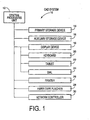
- a computer-aided design (CAD) system 10 includes a central processing unit 12, a primary storage device 14 incorporating a random-access memory (RAM) and a read-only memory (ROM), and an expandable auxiliary storage device 16 such as a hard disc device, an MO storage and a tape storage.
- the central processing unit 12 operates to perform various operations according to control programs stored in the primary storage device 14, while utilizing a temporary data storage function of the primary storage device 14 and auxiliary storage device 16.
- the operations performed by the central processing unit 12 include: operations to generate or modify three-dimensional wire-frame models; operations to define the surfaces of three-dimensional objects from the three-dimensional wire-frame models; operations to generate, expand, contract, modify, translate and rotate solid models on the basis of the three-dimensional wire-frame models whose surfaces have been defined; operations to obtain a sum (a union set), a difference (a difference set) or a product (an intersection set) of three-dimensional models; and operations to define cross sectional shapes of desired portions of three-dimensional models.
- the CAD system 10 further includes a display device 18 such as a cathode ray tube (CRT) or a liquid crystal display (LCD) panel, a keyboard 20, a tablet 22, and a dial 24.
- the display device 18 is adapted to provide visual representation of images such as the three-dimensional models, and operation menu which permits the operator of the system to easily select desired operations to be performed.
- the keyboard 20, tablet 22 and dial 24 function as a data input device through which the operator enters appropriate data necessary to generate three-dimensional models, and numerical control (NC) data for moving the three-dimensional models.
- the data input device is also used for commanding the system to perform the operations to expand, contract, modify, move or rotate the three-dimensional models, to obtain the sum, difference or product of the three-dimensional models, and to select the desired operation through the menu provided on the display device 18.
- the CAD system is equipped with a printer 26, a paper tape puncher 28, and a network controller 30.
- the printer 26 is capable of printing NC data, and other data as displayed on the display device 18 or obtained by the central processing unit 12.
- the paper tape puncher 28 is provided to prepare NC tapes used by machine tools for machining operations.
- the network controller 30 is connected to a work station or machine tools for data communications therebetween.
- each three-dimensional wire-frame model for which the surfaces are defined includes a list of the coordinate values of each vertex (apex) P, and a list of edges (segments) L each of which is defined by adjacent two vertices.
- the three-dimensional wire-frame model is a cube 32 as shown in Fig. 3, by way of example, the list of the vertices P and the list of the edges L are as indicated in TABLES 1 and 2 given below: VERTEX NO.
- the vertices P are represented by the X-, Y- and Z-coordinate values x, y and z in the X-Y-Z rectangular coordinate system, while each edge L is represented by the two vertices corresponding to its opposite ends (start and end points).
- the central processing unit 12 includes edge pair pointing means 38, candidate edge determining means 40, closed-loop edge set determining means 42 and surface defining means 44.
- the edge pair pointing means 38 is adapted to sequentially point or designate pairs of edges selected from the edges constituting the three-dimensional wire-frame model, each pair consisting of two mutually connected edges lying on the same one plane.
- these pairs of mutually connected edges include, for instance: a pair of edges L1 and L2; a pair of edges L2 and L3; a pair of edges L2 and L11; a pair of edges L3 and L12; and a pair of edges L3 and L4.
- the candidate edge determining means 40 is adapted to determine a group of candidate edges consisting the two connected edges of the pair currently pointed by the edge pair pointing means 38, and at least one edge which lies on the same plane as the currently pointed pair of edges.
- the candidate edge determining means 42 determines the edges L1, L2, L3 and L4 as a group of candidate edges, since the edges L3 and L4 lie on the same plane as the pointed pair of edges L1 and L2.
- the closed-loop edge set determining means 42 is adapted to determine whether the pair of edges currently pointed by the edge pair pointing means 38 cooperate with any of the other candidate edges determined by the candidate edge determining means 40, to define a closed loop, namely, a wire frame.
- the closed-loop edge set determining means 42 determines whether the edges L1 and L2 cooperate with the edge L3 and/or the edge L4, to define a closed loop.
- the closed-loop edge set determining means 42 determines the edges defining each closed loop, as a set of closed-loop defining edges, and stores this set of closed-loop defining edges.
- the manner of determining whether the three or more edges define a closed loop is similar to the conventionally practiced manner, the present method of defining the surfaces of a three-dimensional object on the basis of a three-dimensional wire-frame model is different from the conventional method in that the edges (referred to as "candidate edges") to be checked for the above determination by the closed-loop edge set determining means 42 all lie on the same plane.
- the surface defining means 44 is adapted to define a surface or face of the object corresponding to the three-dimensional wire-frame model, on the basis of each set of closed-loop defining edges determined by the closed-loop edge set determining means 44.
- the edges L1, L2, L3 and L4 are determined as a set of closed-loop defining edges by the closed-loop edge set determining means 42, for example, the surface defining means 44 prepares and stores data indicating that a surface S1 is defined by the four edges L1-L4.
- the thus prepared data constitute a part of a list of surfaces wherein the surfaces are defined by respective sets of closed-loop defining edges.
- the surface defining means 44 may incorporate smallest loop determining means 46, which is operated if two or more closed loops are determined by the closed-loop edge set determining means 42.
- the smallest closed loop determining means 46 is adapted to determine or select a smallest one of the closed loops, so that the selected smallest closed loop is used for the surface definition by the surface defining means 44.
- the central processing unit 12 is adapted to execute a surface defining routine illustrated in the flow chart of Fig. 4.
- This surface defining routine is initiated with step SA1 to read the edges (segments) L1-Ln of the three-dimensional wire-frame model under examination.
- the twelve edges L1 through L12 are read out from the edge list (indicated in TABLE 2) stored in the primary storage device 14.
- Step SA1 is followed by step SA2 in which a pair of edges (e.g., L1 and L2) of the wire-frame model is pointed.
- a pair of edges e.g., L1 and L2
- the different pairs of edges are sequentially pointed in a predetermined order. For instance, the edges L1 and L2 are initially pointed as the first pair of edges in step SA2.
- step SA3 determines whether the two edges of the pair pointed in step SA3 are connected to each other and lie on the same one plane). For instance, this determination is effected on the basis of the coordinate values x, y and z of the two vertices (apices) defining the opposite ends of each of the two edges of the currently pointed pair. If two or more pairs of connected edges exit on the same plane, only one of these pairs (e.g., only the first pair) is selected, and the other pair or pairs is/are discarded.
- steps SA2 and SA3 correspond to the edge pair pointing means 38 for sequentially pointing the pairs of mutually connected edges lying on the same plane.
- step SA3 If a negative decision (NO) is obtained in step SA3, the control flow goes to step SA5, while skipping step SA4. If an affirmative decision (YES) is obtained in step SA3, the control flow goes to step SA4 corresponding to the candidate edge determining means 40 described above, to determine whether each of the edges read in step SA1 (all edges L1-L12) of the wire-frame model) lies on the same plane as the pointed point of connected edges. For instance, the edges L3 and L4 are determined to lie on the same plane as the currently pointed pair of connected edges L1 and L2, and these four edges are determined as a group G1 of candidate edges lying on the same plane.
- step SA5 determines whether steps SA2, SA3 and SA4 have been implemented for all of the pairs of edges.
- steps SA2-SA4 are repeatedly implemented until an affirmative decision (YES) is obtained in step SA5.
- YES affirmative decision
- the candidate edge groups Gi determined by the candidate edge determining means 40 in step SA4 are stored.
- step SA6 is effected according to a closed-loop determining sub-routine illustrated in the flow chart of Fig. 5.
- the sub-routine is initiated with step SB1 to determine whether a currently pointed one of the candidate edges Li of the pointed candidate edge group Gi is connected at its end point to another candidate edge Li. If a negative decision (NO) is obtained in step SB1, the control flow goes to step SB8 to determine whether the determination has been effected for all of the candidate edges Li of the group Gi under examination. If a negative decision (NO) is obtained in step SB8, the control flow goes back to step SB1.
- the candidate edges of the group Gi under examination are sequentially pointed, and the determination in step SB1 is effected for all candidate edges Li of the group Gi under examination.
- step SB1 If an affirmative decision (YES) is obtained in step SB1, the control flow goes to step SB2 to store the next candidate edge to which the end point of the candidate edge Li under examination is connected. Step SB2 is followed by step SB3 to determine whether the stored candidate edge is connected at its end point to another candidate edge of the group Gi. If an affirmative decision (YES) is obtained, the control flow goes to step SB4 to store the next candidate edge to which the end point of the candidate edge is connected. Step SB4 is followed by step SB5 to determine whether the end point of the stored candidate edge is the same as the start point of the candidate edge for which the affirmative decision (YES) was obtained in step SB1.
- step SB5 If a negative decision (NO) is obtained in step SB5, the control flow goes to step SB6 to determine whether the determination has been effected for all of the candidate edges Li of the group Gi under examination. Steps SB3-SB5 are repeatedly implemented until an affirmative decision (YES) is obtained in step SB5.
- step SB5 When the affirmative decision (YES) is obtained in step SB5, the control flow goes to step SB7 in which the candidate edges Li of the group Gi which have been determined to be connected connected end to end are determined as a set of closed-loop defining edges. Step SB7 is followed by step SB8 to determine whether the determination has been effected for all candidate edges of the group Gi under examination. Thus, steps SB1-SB7 are repeated for all of the candidate edges of the group Gi.
- step SA6 the control flow goes to step SA6 if an affirmative decision (YES) is obtained in step SA6 in which the determined set of closed-loop defining edges is stored in the primary storage device 14.
- the candidate edge group G1 consisting of the candidate edges L1, L2, L3 and L4
- all of the four candidate edges L1-L4 cooperate with each other to define a closed loop, namely, a surface S1 of a three-dimensional object corresponding to the three-dimensional wire-frame model in question.
- the four edges L1-L4 are stored as a set of closed-loop defining edges in relation to the surface S1, as part of the surface list, in the primary storage memory 14, as indicated in Fig. 2.
- steps SA6 and SA7 correspond to the closed-loop edge set determining means 42 for determining a set of closed-loop defining edges which belong to the candidate edge group Gi and which lie on the same plane.
- Step SA7 is followed by step SA8 indicated above, to determine whether steps SA6 and SA7 have been performed for all of the candidate edge groups Gi. Steps SA6 and SA7 are repeatedly implemented until an affirmative decision (YES) is obtained in step SA8.
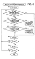
- step SC1 The sub-routine of Fig. 6 is initiated with step SC1 in which counters "a” and “b" are set at “1".
- the counters "a” and “b” correspond to the respective closed loops "a” and “b” which are defined by the candidate edges Li of the group Gi under examination.
- Step SC1 is followed by step SC2 to determine whether the two or more edges of the closed loop "a” are the same as the two or more edges of the closed loop "b”. If a negative decision (NO) is obtained in step SC2, the control flow goes to step SC7 and the subsequent steps to increment the counters "a” and "b".
- step SC2 If an affirmative decision (YES) is obtained in step SC2, the control flow goes to step SC3 to determine whether the number of the closed loop "a" is larger than the number of the closed loop "b". If an affirmative decision (YES) is obtained in step SC3, the control flow goes to step SC4 to discard the closed loop "a”. If a negative decision (NO) is obtained in step SC3, the control flow goes to step SC5 to determine whether the number of the edges of the closed loop "a" is smaller than the number of the edges of the closed loop "b”. If an affirmative decision (YES) is obtained in step SC5, the control flow goes to step SC6 to discard the closed loop "b". If a negative decision (NO) is obtained in step SC5, the control flow goes to step SC7 to increment the counter "b".
- Step SC7 is followed by step SC8 to determine whether the content of the counter "b" is equal to "n" which represents the number of the closed loops defined by the group Gi under examination. If a negative decision (NO) is obtained in step SC8, the control flow goes back to step SC2. Steps SC2-SC7 are repeatedly implemented until an affirmative decision (YES) is obtained in step SC8. When the affirmative decision is obtained in step SC8, the control flow goes to step SC9 to increment the counter "a”. Step SC8 is followed by step SC10 to determine whether the content of the counter "a" is equal to "n”. If a negative decision (NO) is obtained steps SC2-SC9 are repeatedly implemented until an affirmative decision (YES) is obtained. The sub-routine of Fig. 6 is terminated when the affirmative decision is obtained in step SC10.
- step SA9 is followed by step SA10 corresponding to the surface defining means 44, in which all of the surfaces Sn (e.g., surfaces S1 through S6) of the three-dimensional object are defined by the respective sets of closed-loop defining edges Li, and a list of the surfaces Sn is stored in the primary storage device 14, as indicated in TABLE 3 by way of example.
- the surface S1 is defined by the four edges L1, L2, L3 and L4, while the surface S2 is defined by the four edges L3, L11, L7 and L12, for instance. If two or more sets of closed-loop defining edges exist for the same surface Sn, only one of these sets is stored, and the remainder is discarded.
- the edge pair pointing means 38 operates in steps SA2 and SA3 to sequentially point the pairs of edges, each pair consisting of two mutually connected edges which lie on the same plane.
- the candidate edge determining means 40 operates to determine groups Gi of candidate edges, each group Gi consisting of the currently pointed pair of mutually connected edges and one or more edges lying on the same plane as the pointed pair of edges.
- the closed-loop edge set determining means 42 operates to determine sets of closed-loop defining edges, each set consisting of the edges which define a closed loop on the plane of each group Gi under examination.
- the surface defining means 44 operates to define the surfaces on the basis of the respective sets of closed-loop defining edges determined by the closed-loop edge set determining means 42.
- the determination as to whether the edges define a closed loop or wire frame is effected for each group Gi of candidate edges. Since all of the candidate edges of each group Gi including the currently pointed pair of connected edges lie on the same plane, the number of the edges for which the determination is effected for each edge of the wire-frame model is considerably smaller than the number of edges for which similar determination is conventionally effected for each edge. In the conventional method, the determination for each edge is effected for all of the other edges. Accordingly, the efficiency of surface definition on the basis of the three-dimensional wire-frame model according to the present invention is significantly improved.
- a closed-loop determining sub-routine as illustrated in the flow chart of Fig. 5 is executed for determining the closed loops defining the surfaces of a three-dimensional object, on the basis of the corresponding wire-frame model.
- this conventional method is applied to the wire-frame model as illustrated in Fig.
- the determination to find closed loops involving the edge L1 should be effected as many as 14 times corresponding to the following 14 closed loops: L1-L2-L3-L4; L1-L2-L3-L-12-L8-L9; L1-L2-L3-L12-L7-L6-L5-L9; L1-L2-L11-L6-L5-L9; L1-L2-L11-L6-L5-L8-L12-L4; L1-L2-L11-L7-L8-L9, L1-L2-L11-L7-L12-L4; L1-L10-L5-L9; L1-L10-L5-L8-L7-L11-L3-L4; L1-L10-L5-L8-L12-L4; L1-L10-L6-L7-L8-L9; L1-L10-L6-L7-L12-L4; L1-L10-
- step SA6 is repeated for the six groups Gi of candidate edges lying on respective six planes, so that the number of determinations that should be effected in steps SB1, SB3 and SB5 is considerably reduced, and the required data processing time is accordingly reduced.
- the candidate edge determining means 40 or step SA3 is adapted to determine all groups Gi of candidate edges corresponding to respective planes, before the closed-loop edge set determining means 42 or step SA6, SA7 determines whether the candidate edges of each group Gi include the edges defining a closed loop.
- the routine of Fig. 4 may be modified such that the candidate edge determining means 40 or step SA3 and the closed-loop edge set determining means 42 are operated or performed alternatively so that the determination by the closed-loop edge set determining means 42 (in step SA6, SA7) is followed by the determination of each candidate edge group Gi by the candidate edge determining means 40 (in step SA3).
- step SA8 is eliminated, and step SA5 is moved so that step SA7 is followed by step SA5.
- control flow goes back to step SA2 if the negative decision (NO) is obtained in step SA5, so that steps SA2-SA7 are repeatedly implemented until the determination by the closed-loop edge set determining means 42 has been effected for all candidate edge groups Gi determined by the candidate edge determining means 40.
- the edge pair pointing means 38 is adapted to sequentially point pairs of edges of the three-dimensional wire-frame model, in step SA2, and determine in step SA3 whether the two edges of each pointed pair are connected to each other and lie on the same plane.
- the edge pair pointing means 38 may be adapted to sequentially point pairs of two mutually connected edges in step SA2.
- step SA3 is not necessary, since the two mutually connected edges of each pair necessarily lie on the same plane.
- step SA9 may be eliminated from the routine of Fig. 4, if the routine is applied to a three-dimensional wire-frame model wherein the candidate edge groups Gi do not have any group whose candidate edges define two or more closed loops.
- step SA3 is formulated to determine whether the two edges of the pointed pair are connected to each other, as well as whether the two edges lie on the same plane. However, the former determination may be eliminated.
- Computer-aided method and apparatus for defining surfaces (S) of a three-dimensional object (32) on the basis of a three-dimensional wire-frame model wherein a plurality of pairs of edges (Li) selected from edges which constitute the three-dimensional wire-frame model are sequentially pointed (38, SA2, SA3), each pointed pair consisting of two edges lying on the same plane, and a group (Gi) of candidate edges is determined (40, SA4), the group consisting of the currently pointed pair of edges and at least one edge lying on the same plane as the edges of the currently pointed pair, so that those candidate edges of the determined group which cooperate to define a closed loop are determined as a set of closed-loop defining edges (42, SA6, SA7), and a surface (S) of the three-dimensional object is defined on the basis of the set of closed-loop defining edges (44, SA10).
- a plurality of pairs of edges (Li) selected from edges which constitute the three-dimensional wire-frame model are sequentially pointed (38, SA2, SA3), each pointed pair
Landscapes
- Physics & Mathematics (AREA)
- Engineering & Computer Science (AREA)
- General Physics & Mathematics (AREA)
- Theoretical Computer Science (AREA)
- Software Systems (AREA)
- Geometry (AREA)
- Computer Graphics (AREA)
- Algebra (AREA)
- Mathematical Analysis (AREA)
- Mathematical Optimization (AREA)
- Mathematical Physics (AREA)
- Pure & Applied Mathematics (AREA)
- Image Generation (AREA)
- Processing Or Creating Images (AREA)
Description
to assign an edge to a current loop attached to a face, to mark the edge as having been used for the face, and to find the next edge on the loop by finding that edge which starts from the endpoint of the current edge, repeating the process until the edge is closed. If there are still unmarked edges that belong to the face, a new loop is created. The whole process is repeated until all the edges that belong to the face are marked.
| VERTEX NO. | X-COORDINATE | Y-COORDINATE | Z-COORDINATE | |
| No. 1 | P1 | x1 | y1 | z1 |
| No. 2 | P2 | x2 | y2 | z2 |
| No. 3 | P3 | x3 | y3 | z3 |
| No. 4 | P4 | x4 | y4 | z4 |
| No. 5 | P5 | x5 | y5 | z5 |
| No. 6 | P6 | x6 | y6 | z6 |
| No. 7 | P7 | x7 | y7 | z7 |
| No. 8 | P8 | x8 | y8 | z8 |
| EDGE NO. | VERTEX N0. | EDGE NO. | VERTEX NO. | ||
| No. 1 | L1 | P1, P2 | No. 7 | L7 | P7, P8 |
| No. 2 | L2 | P2, P3 | No. 8 | L8 | P8, P5 |
| No. 3 | L3 | P3, P4 | No. 9 | L9 | P1, P5 |
| No. 4 | L4 | P4, P1 | No. 10 | L10 | P2, P6 |
| No. 5 | L5 | P5, P6 | No. 11 | L11 | P3, P7 |
| No. 6 | L6 | P6, P7 | No. 12 | L12 | P4, P8 |
| SURFACE NO. | EDGE NO. | |
| No. 1 | S1 | L1, L2, L3, L4 |
| No. 2 | S2 | L3, L11, L7, L12 |
| No. 3 | S3 | L5, L8, L7, L6 |
| No. 4 | S4 | L1, L9, L5, L10 |
| No. 5 | S5 | L4, L12, L8, L9 |
| No. 6 | S6 | L2, L10, L6, L11 |
Claims (6)
- A method of automatically defining surfaces (S) of a three-dimensional object (32) on the basis of a three-dimensional wire-frame model, using a computer (12), characterized by comprising:an edge pair pointing step (SA2, SA3) of sequentially pointing a plurality of pairs of edges (Li) selected from edges which constitute said three-dimensional wire-frame model, each of said pairs of edges consisting of two edges lying on the same plane;a candidate edge determining step (SA4) of determining a group (Gi) of candidate edges consisting of the edges of a currently pointed one of said plurality of pairs and at least one edge which lies on the same plane as the edges of said currently pointed one of said plurality of pairs;a closed-loop edge set determining step (SA6, SA7) of determining, as a set of closed-loop defining edges, those ones of said candidate edges of said group which cooperate to define a closed loop; anda surface defining step (SA10) of defining a surface (S) of said three-dimensional object, on the basis of said set of closed-loop defining edges.
- A method according to claim 1, wherein said edge pair pointing step (SA2, SA3) comprises sequentially pointing said plurality of pairs of edges, each pair consisting of two mutually connected edges lying on the same plane.
- A method according to claim 1 or 2, wherein said three-dimensional wire-frame model includes coordinate values, in a three-dimensional coordinate system, of each of two vertices defining each of said edges of said three-dimensional wire-frame model, and said surface defining step (SA10) comprises preparing a list of surfaces wherein each of said surfaces is represented by said set of closed-loop defining edges each defined by the two vertices whose coordinate values are known.
- A computer-aided apparatus for defining surfaces (S) of a three-dimensional object (32) on the basis of a three-dimensional wire-frame model, characterized by comprising:edge pair pointing means (38) for sequentially pointing a plurality of pairs of edges (Li) selected from edges which constitute said three-dimensional wire-frame model, each of said pairs of edges consisting of two edges lying on the same plane;candidate edge determining means (40) for determining a group (Gi) of candidate edges consisting of the edges of a currently pointed one of said plurality of pairs and at least one edge which lies on the same plane as the edges of said currently pointed one of said plurality of pairs;closed-loop edge set determining means (42) for determining, as a set of closed-loop defining edges, those ones of said candidate edges of said group which cooperate to define a closed loop; andsurface defining means (44) for defining a surface (S) of said three-dimensional object, on the basis of said set of closed-loop defining. edges.
- A computer-aided apparatus according to claim 4, wherein said edge pair pointing means (38) comprises means for sequentially pointing said plurality of pairs of edges, each pair consisting of two mutually connected edges lying on the same plane.
- A computer-aided apparatus according to claim 4 or 5, wherein said three-dimensional wire-frame model includes coordinate values, in a three-dimensional coordinate system, of each of two vertices defining each of said edges of said three-dimensional wire-frame model, and said surface defining step (SA10) comprises preparing a list of surfaces wherein each of said surfaces is represented by said set of closed-loop defining edges each defined by the two vertices whose coordinate values are known.
Applications Claiming Priority (3)
| Application Number | Priority Date | Filing Date | Title |
|---|---|---|---|
| JP20170896A JP3162630B2 (en) | 1996-07-31 | 1996-07-31 | Surface definition method and apparatus for wireframe model |
| JP20170896 | 1996-07-31 | ||
| JP201708/96 | 1996-07-31 |
Publications (3)
| Publication Number | Publication Date |
|---|---|
| EP0822522A2 EP0822522A2 (en) | 1998-02-04 |
| EP0822522A3 EP0822522A3 (en) | 1998-08-19 |
| EP0822522B1 true EP0822522B1 (en) | 2002-10-23 |
Family
ID=16445618
Family Applications (1)
| Application Number | Title | Priority Date | Filing Date |
|---|---|---|---|
| EP97113146A Expired - Lifetime EP0822522B1 (en) | 1996-07-31 | 1997-07-30 | Method and apparatus for defining surfaces of three-dimensional object from three-dimensional wire-frame model |
Country Status (6)
| Country | Link |
|---|---|
| US (1) | US5971583A (en) |
| EP (1) | EP0822522B1 (en) |
| JP (1) | JP3162630B2 (en) |
| KR (1) | KR100254836B1 (en) |
| CA (1) | CA2211887C (en) |
| DE (1) | DE69716532T2 (en) |
Families Citing this family (17)
| Publication number | Priority date | Publication date | Assignee | Title |
|---|---|---|---|---|
| JP3341549B2 (en) * | 1995-11-14 | 2002-11-05 | ミノルタ株式会社 | 3D shape data processing device |
| US6259461B1 (en) * | 1998-10-14 | 2001-07-10 | Hewlett Packard Company | System and method for accelerating the rendering of graphics in a multi-pass rendering environment |
| US6230062B1 (en) | 1999-01-08 | 2001-05-08 | Voyan Technology | Adaptation to unmeasured variables |
| US6278898B1 (en) * | 1999-04-07 | 2001-08-21 | Voyan Technology | Model error bounds for identification of stochastic models for control design |
| US6771818B1 (en) * | 2000-04-04 | 2004-08-03 | Microsoft Corporation | System and process for identifying and locating people or objects in a scene by selectively clustering three-dimensional regions |
| KR100333913B1 (en) * | 2000-06-26 | 2002-04-22 | 이충전 | A cooling apparatus of vending mechine |
| JP2003044530A (en) * | 2001-07-30 | 2003-02-14 | Toshiba Corp | Structure shape definition device, structure shape definition method, structure shape definition program, and design drawing creation device |
| US6819966B1 (en) | 2003-12-06 | 2004-11-16 | Paul E. Haeberli | Fabrication of free form structures from planar materials |
| US8295546B2 (en) | 2009-01-30 | 2012-10-23 | Microsoft Corporation | Pose tracking pipeline |
| US8811938B2 (en) | 2011-12-16 | 2014-08-19 | Microsoft Corporation | Providing a user interface experience based on inferred vehicle state |
| EP2811463B1 (en) * | 2013-06-04 | 2018-11-21 | Dassault Systèmes | Designing a 3d modeled object with 2d views |
| EP2874118B1 (en) | 2013-11-18 | 2017-08-02 | Dassault Systèmes | Computing camera parameters |
| EP3032495B1 (en) | 2014-12-10 | 2019-11-13 | Dassault Systèmes | Texturing a 3d modeled object |
| EP3188033B1 (en) | 2015-12-31 | 2024-02-14 | Dassault Systèmes | Reconstructing a 3d modeled object |
| EP4131172A1 (en) | 2016-09-12 | 2023-02-08 | Dassault Systèmes | Deep convolutional neural network for 3d reconstruction of a real object |
| CN109426832A (en) * | 2017-08-30 | 2019-03-05 | 湖南拓视觉信息技术有限公司 | Closed loop detection method, storage medium and electronic equipment in scene three-dimensional modeling |
| CN115239884A (en) * | 2022-07-22 | 2022-10-25 | 中船黄埔文冲船舶有限公司 | A method and device for reconstructing a three-dimensional model in a middle assembly |
Family Cites Families (13)
| Publication number | Priority date | Publication date | Assignee | Title |
|---|---|---|---|---|
| JPH0821089B2 (en) * | 1986-04-25 | 1996-03-04 | 東芝機械株式会社 | Solid model shape definition method in CAD / CAM system |
| WO1989009975A1 (en) * | 1988-04-07 | 1989-10-19 | Matsushita Electric Industrial Co., Ltd. | Solid modelling method |
| US5276783A (en) * | 1989-11-21 | 1994-01-04 | International Business Machines Corporation | Tessellating complex polygons in modeling coordinates |
| GB2259432A (en) * | 1991-09-06 | 1993-03-10 | Canon Res Ct Europe Ltd | Three dimensional graphics processing |
| GB2274376B (en) * | 1992-12-09 | 1996-12-18 | Honda Motor Co Ltd | Method of and system for producing solid models |
| JP2627608B2 (en) * | 1993-07-26 | 1997-07-09 | 日本アイ・ビー・エム株式会社 | Solid model synthesizing apparatus and synthesizing method |
| CA2129477C (en) * | 1993-08-06 | 1999-07-06 | Koichi Nishizaka | Method of generating or modifying solid model of an object and apparatus suitable for practicing the method |
| US5416893A (en) * | 1993-10-26 | 1995-05-16 | Hewlett-Packard Co. | Method for displaying edging or decaling of an object in a graphics display |
| JPH07311858A (en) * | 1994-05-18 | 1995-11-28 | Sony Corp | Free curved surface creation method and free curved surface creation device |
| US5655063A (en) * | 1994-06-28 | 1997-08-05 | Computervision Corporation | Topology based tolerancing for geometric modeling operations |
| JPH0821089A (en) * | 1994-07-05 | 1996-01-23 | Masato Sugano | Locking operating tool |
| US5659493A (en) * | 1995-03-03 | 1997-08-19 | Ford Motor Company | Virtual machining techniques for modifying computer models of parts |
| US5742291A (en) * | 1995-05-09 | 1998-04-21 | Synthonics Incorporated | Method and apparatus for creation of three-dimensional wire frames |
-
1996
- 1996-07-31 JP JP20170896A patent/JP3162630B2/en not_active Expired - Fee Related
-
1997
- 1997-07-29 CA CA002211887A patent/CA2211887C/en not_active Expired - Fee Related
- 1997-07-30 EP EP97113146A patent/EP0822522B1/en not_active Expired - Lifetime
- 1997-07-30 DE DE69716532T patent/DE69716532T2/en not_active Expired - Fee Related
- 1997-07-31 US US08/904,427 patent/US5971583A/en not_active Expired - Fee Related
- 1997-07-31 KR KR1019970036492A patent/KR100254836B1/en not_active Expired - Fee Related
Also Published As
| Publication number | Publication date |
|---|---|
| EP0822522A3 (en) | 1998-08-19 |
| EP0822522A2 (en) | 1998-02-04 |
| CA2211887C (en) | 2001-10-09 |
| KR100254836B1 (en) | 2000-05-01 |
| DE69716532D1 (en) | 2002-11-28 |
| JP3162630B2 (en) | 2001-05-08 |
| CA2211887A1 (en) | 1998-01-31 |
| KR980010879A (en) | 1998-04-30 |
| JPH1049708A (en) | 1998-02-20 |
| US5971583A (en) | 1999-10-26 |
| DE69716532T2 (en) | 2003-06-26 |
Similar Documents
| Publication | Publication Date | Title |
|---|---|---|
| US5971583A (en) | Method and apparatus for defining surfaces of three-dimensional object from three-dimensional wire-frame model | |
| EP0598406A1 (en) | Method of and apparatus for producing register mark pattern | |
| JP3268666B2 (en) | Computer graphics production equipment | |
| JP3792584B2 (en) | Tool path surface calculation method, tool path surface calculation program, and recording medium recording tool path surface calculation program | |
| JP2005078207A (en) | 3D data creation system, 3D data creation method, and program | |
| EP0822521A2 (en) | Method and apparatus for generating three-dimensional solid models | |
| JPS62251965A (en) | Solid model form defining system in cad/cam system | |
| JP2001222305A (en) | Sheet metal integral supporting system and storage medium with stored graphic data generation management program | |
| EP0500936A1 (en) | Method of depicting numeric control data for machining polyhedron | |
| JPH0616290B2 (en) | Method for defining shape of three-dimensional connected body | |
| JP3127551B2 (en) | Layout device | |
| Kuric | Computer Aided Systems | |
| JP3848717B2 (en) | 3D model generation system | |
| US5151864A (en) | Method of generating cutting passes of complex curved surface | |
| JPS62263564A (en) | Coordinate grid creation support method and device | |
| JPH04158481A (en) | Preparing method for numerical analysis for product design | |
| JPH0644350A (en) | Method for generating solid-state element of finite element method mainly composed of hexahedron due to plane display | |
| JPH06314317A (en) | Stereoscopic diagram drawing method for cad data | |
| JPH1011490A (en) | Design support equipment | |
| Lewis et al. | IFECS—an interactive finite element computing system | |
| JPS60134979A (en) | Input system of three-dimensional graphic information | |
| JPH05265171A (en) | Layout device | |
| Sonmez | Interactive computer aided drawing, manipulating, storing, retrieving and analyses of overall facility layout | |
| Stoiljković | CAE in Sheet Forming | |
| Evans et al. | CAD/CAM: improved design quality, increased productivity |
Legal Events
| Date | Code | Title | Description |
|---|---|---|---|
| PUAI | Public reference made under article 153(3) epc to a published international application that has entered the european phase |
Free format text: ORIGINAL CODE: 0009012 |
|
| 17P | Request for examination filed |
Effective date: 19970730 |
|
| AK | Designated contracting states |
Kind code of ref document: A2 Designated state(s): DE ES FR GB IT SE |
|
| AX | Request for extension of the european patent |
Free format text: AL;LT;LV;RO;SI |
|
| PUAL | Search report despatched |
Free format text: ORIGINAL CODE: 0009013 |
|
| AK | Designated contracting states |
Kind code of ref document: A3 Designated state(s): AT BE CH DE DK ES FI FR GB GR IE IT LI LU MC NL PT SE |
|
| AX | Request for extension of the european patent |
Free format text: AL;LT;LV;RO;SI |
|
| AKX | Designation fees paid |
Free format text: DE ES FR GB IT SE |
|
| RBV | Designated contracting states (corrected) |
Designated state(s): DE ES FR GB IT SE |
|
| GRAG | Despatch of communication of intention to grant |
Free format text: ORIGINAL CODE: EPIDOS AGRA |
|
| 17Q | First examination report despatched |
Effective date: 20020215 |
|
| GRAG | Despatch of communication of intention to grant |
Free format text: ORIGINAL CODE: EPIDOS AGRA |
|
| GRAH | Despatch of communication of intention to grant a patent |
Free format text: ORIGINAL CODE: EPIDOS IGRA |
|
| GRAA | (expected) grant |
Free format text: ORIGINAL CODE: 0009210 |
|
| GRAH | Despatch of communication of intention to grant a patent |
Free format text: ORIGINAL CODE: EPIDOS IGRA |
|
| AK | Designated contracting states |
Kind code of ref document: B1 Designated state(s): DE ES FR GB IT SE |
|
| PG25 | Lapsed in a contracting state [announced via postgrant information from national office to epo] |
Ref country code: IT Free format text: LAPSE BECAUSE OF FAILURE TO SUBMIT A TRANSLATION OF THE DESCRIPTION OR TO PAY THE FEE WITHIN THE PRESCRIBED TIME-LIMIT;WARNING: LAPSES OF ITALIAN PATENTS WITH EFFECTIVE DATE BEFORE 2007 MAY HAVE OCCURRED AT ANY TIME BEFORE 2007. THE CORRECT EFFECTIVE DATE MAY BE DIFFERENT FROM THE ONE RECORDED. Effective date: 20021023 |
|
| REG | Reference to a national code |
Ref country code: GB Ref legal event code: FG4D |
|
| REF | Corresponds to: |
Ref document number: 69716532 Country of ref document: DE Date of ref document: 20021128 |
|
| PG25 | Lapsed in a contracting state [announced via postgrant information from national office to epo] |
Ref country code: SE Free format text: LAPSE BECAUSE OF FAILURE TO SUBMIT A TRANSLATION OF THE DESCRIPTION OR TO PAY THE FEE WITHIN THE PRESCRIBED TIME-LIMIT Effective date: 20030123 |
|
| ET | Fr: translation filed | ||
| PG25 | Lapsed in a contracting state [announced via postgrant information from national office to epo] |
Ref country code: ES Free format text: LAPSE BECAUSE OF FAILURE TO SUBMIT A TRANSLATION OF THE DESCRIPTION OR TO PAY THE FEE WITHIN THE PRESCRIBED TIME-LIMIT Effective date: 20030429 |
|
| PLBE | No opposition filed within time limit |
Free format text: ORIGINAL CODE: 0009261 |
|
| STAA | Information on the status of an ep patent application or granted ep patent |
Free format text: STATUS: NO OPPOSITION FILED WITHIN TIME LIMIT |
|
| 26N | No opposition filed |
Effective date: 20030724 |
|
| PGFP | Annual fee paid to national office [announced via postgrant information from national office to epo] |
Ref country code: FR Payment date: 20040708 Year of fee payment: 8 |
|
| PGFP | Annual fee paid to national office [announced via postgrant information from national office to epo] |
Ref country code: GB Payment date: 20040728 Year of fee payment: 8 |
|
| PGFP | Annual fee paid to national office [announced via postgrant information from national office to epo] |
Ref country code: DE Payment date: 20040812 Year of fee payment: 8 |
|
| PG25 | Lapsed in a contracting state [announced via postgrant information from national office to epo] |
Ref country code: GB Free format text: LAPSE BECAUSE OF NON-PAYMENT OF DUE FEES Effective date: 20050730 |
|
| PG25 | Lapsed in a contracting state [announced via postgrant information from national office to epo] |
Ref country code: DE Free format text: LAPSE BECAUSE OF NON-PAYMENT OF DUE FEES Effective date: 20060201 |
|
| GBPC | Gb: european patent ceased through non-payment of renewal fee |
Effective date: 20050730 |
|
| PG25 | Lapsed in a contracting state [announced via postgrant information from national office to epo] |
Ref country code: FR Free format text: LAPSE BECAUSE OF NON-PAYMENT OF DUE FEES Effective date: 20060331 |
|
| REG | Reference to a national code |
Ref country code: FR Ref legal event code: ST Effective date: 20060331 |