EP0821418B1 - Piezoelectric mechanism for gas lighters with externally closed telescopic body - Google Patents
Piezoelectric mechanism for gas lighters with externally closed telescopic body Download PDFInfo
- Publication number
- EP0821418B1 EP0821418B1 EP96940664A EP96940664A EP0821418B1 EP 0821418 B1 EP0821418 B1 EP 0821418B1 EP 96940664 A EP96940664 A EP 96940664A EP 96940664 A EP96940664 A EP 96940664A EP 0821418 B1 EP0821418 B1 EP 0821418B1
- Authority
- EP
- European Patent Office
- Prior art keywords
- telescopic body
- striker
- telescopic
- ramps
- ramp
- Prior art date
- Legal status (The legal status is an assumption and is not a legal conclusion. Google has not performed a legal analysis and makes no representation as to the accuracy of the status listed.)
- Expired - Lifetime
Links
- 230000007246 mechanism Effects 0.000 title claims abstract description 56
- 230000014759 maintenance of location Effects 0.000 claims description 7
- 230000000295 complement effect Effects 0.000 claims description 5
- 230000000149 penetrating effect Effects 0.000 claims description 3
- 230000000717 retained effect Effects 0.000 claims description 3
- 238000005304 joining Methods 0.000 claims description 2
- 238000000034 method Methods 0.000 abstract description 8
- 230000008569 process Effects 0.000 abstract description 8
- 239000013078 crystal Substances 0.000 abstract description 5
- 238000011084 recovery Methods 0.000 description 19
- 230000006835 compression Effects 0.000 description 11
- 238000007906 compression Methods 0.000 description 11
- 230000004913 activation Effects 0.000 description 4
- 230000000694 effects Effects 0.000 description 4
- 238000003780 insertion Methods 0.000 description 4
- 230000037431 insertion Effects 0.000 description 4
- 230000009471 action Effects 0.000 description 3
- 238000002485 combustion reaction Methods 0.000 description 3
- 239000000428 dust Substances 0.000 description 3
- 230000000903 blocking effect Effects 0.000 description 2
- 230000008030 elimination Effects 0.000 description 2
- 238000003379 elimination reaction Methods 0.000 description 2
- 238000004519 manufacturing process Methods 0.000 description 2
- 239000002245 particle Substances 0.000 description 2
- 238000000926 separation method Methods 0.000 description 2
- 238000004904 shortening Methods 0.000 description 2
- 206010061307 Neck deformity Diseases 0.000 description 1
- 230000003213 activating effect Effects 0.000 description 1
- 230000009172 bursting Effects 0.000 description 1
- 238000010276 construction Methods 0.000 description 1
- 230000007797 corrosion Effects 0.000 description 1
- 238000005260 corrosion Methods 0.000 description 1
- 230000006866 deterioration Effects 0.000 description 1
- 231100001261 hazardous Toxicity 0.000 description 1
- 230000006698 induction Effects 0.000 description 1
- 239000000463 material Substances 0.000 description 1
- 244000045947 parasite Species 0.000 description 1
- 230000002265 prevention Effects 0.000 description 1
- 230000000750 progressive effect Effects 0.000 description 1
Images






Classifications
-
- F—MECHANICAL ENGINEERING; LIGHTING; HEATING; WEAPONS; BLASTING
- F23—COMBUSTION APPARATUS; COMBUSTION PROCESSES
- F23Q—IGNITION; EXTINGUISHING-DEVICES
- F23Q3/00—Igniters using electrically-produced sparks
- F23Q3/002—Igniters using electrically-produced sparks using piezoelectric elements
Definitions
- the present invention as expressed in the title of this specification, consists of a piezoelectric mechanism for gas lighters, offering notable advantageous characteristics versus conventional ones.
- the piezoelectric mechanisms used for the production of the lighting spark is basically made up of a pair of telescopic bodies which are to be found mutually assisted by a spring which keeps them in the maximum extended position, being equipped with means which limit the total accidental separation. Solidly attached to one of these bodies are indistinctly located the crystal or piezoelectric element which provides the lighting spark when the striker hammer makes impact on the same.
- the piezoelectric element is in turn found located between a metallic part named “anvil” and another part which is the one which in reality receives the impact of the striker hammer, called “base” or "stop part".
- the main object of the invention is constituted by the presentation of an improved shape in the structure of the exterior telescopic body to achieve prevention of the ingress of dust and foreign bodies into the inside of the telescopic assembly in which the actuation mechanisms are enclosed.
- the striker hammer plays in the axial cavity of the interior telescopic body, and in the rest position it is found spaced from the piezoelectric element, due to the existance of retention means which will be described hereinafter.
- the guiding means of the striker hammer are defined by a pair of confronted longitudinal slots, which run through the wall of one of the tubular bodies of the telescopic assembly, the slots housing two diametrical projections of the striker hammer.
- the striker hammer In the condition of rest of the mechanism, the striker hammer is found retained by its transversal projections, in two notches, each open at a side of the respective longitudinal groove of said tubular body, being inserted in the notches when the striker hammer is forced to effect a rotational movement.
- the striker hammer performs a small rotation, both for exiting from the retention notches and for entering the same after the impact, to originate the rearming of the mechanisms, at the end of the compression run of the telescopic assembly, and during the distension of the same, respectively, the diametrical projections of the striker hammer are pressed by the ramp edges of two windows provided on the other telescopic body, where said projections also play.
- the Spanish Patent application P-8902741 (ES-A-2 014 189), describes and claims a piezoelectric mechanism for gas lighters by means of which the elimination of angular movement between both telescopic components is achieved, providing on the exterior body, a pair of projections which act with a key function, playing in the interior of the actual slots provided on the interior telescopic body for the axial movement of the striker hammer. Due to this, said slots need to be of greater length than that necessary for the guiding of the hammer.
- the spring which assists the striker hammer is partially or totally guided inside the telescopic body which houses the striker hammer, abutting its other end on a cover which is attached on the free end of said body, since it is equipped with projections with sawtoothed section, the projections being inserted in respective lateral windows existing on the confronted walls of the telescopic body, becoming immobilized in said fixed position.
- the present invention offers a piezoelectric mechanism for gas lighters, with telescopic body, which is closed to the exterior. Consequently, the exterior telescopic body which conventionally presented open windows towards the exterior and the upper and lower edges of which are inclined to form the ramps which force the rotation of the striker hammer, during the release and the rearming, is replaced by a body which is closed to the exterior, on two interior opposed walls of which, are provided two recesses which present the ramps which guide said striker projections, both in the process of assembly of both telescopic bodies and during the said release and rearming phases of the striker.
- the upper or first ramps cause the rearming and the lower ramps or second ramps, the release.
- the piezoelectric mechanism of the invention comprises a first and a second telescopic body, as well as a first spring which is capable of maintaining both bodies separated from each other at a determined distance.
- the first telescopic body fixedly houses a piezoelectric element, whilst inside the interior of the second telescopic body a striker is housed, retained in a first position, spaced from the piezoelectric element.
- the mechanism comprises a second spring which impels the striker against the piezoelectric element, means for preventing the relative rotation between the telescopic bodies as well as means for releasing the striker from its first position.
- the means for releasing the striker are associated to the telescopic bodies in such a manner that, when sufficient compression force is applied, the two bodies move close to each other and, simultaneously produce the release of the striker from its first position, in such a manner that the second spring may impel the striker against the piezoelectric element with sufficient force so that the impact generates the electric energy for producing a lighting spark.
- the mechanism also includes means for transmitting the electric energy to electrodes arranged in a combustion chamber.
- the first telescopic body or interior body houses the piezoelectric element assembled between an anvil and a stopping part.
- the striker is impelled against the stopping part.
- the second telescopic body or exterior body comprises on the interior wall of its internal cavity, a pair of recesses as well as ramps which guide the striker.
- the striker presents an essentially cylindrical shape and two diametrically opposed lateral projections which are guided in the recesses and ramps in the second telescopic body, as well as means for connecting with the second spring.
- the means for releasing the striker comprise a lower ramp or second ramp provided in relation with each one of the recesses of the second body, in such a manner that when the telescopic bodies are moved one towards the other during the compression movement, the projections of the striker contact with said second ramps related to the recesses, so as to rotate the striker out of its first position.
- the recesses also respectively present an upper ramp or first ramp in order to move the projections of the striker back towards their first position when the compression strength is eliminated and the telescopic bodies return to their rest position.
- the first telescopic body advantageously presents a paraxial slot which divides its interior end into two legs presenting curved, transversal sections which, in their exterior part, are essentially complementary to the curvature of at least one section of the axial perforation provided in the second telescopic body.
- Said paraxial slot extends from the interior end or first end of the first telescopic body towards its exterior portion in such a manner that it permits a sufficient travel to allow the axial movement of the diametrical projections of the striker in the release and the recovery of the striker.
- recesses or notches are each provided on diametrically opposed sharp edges. These notches form retention means in which the diametrical projections of the striker rest in their first position.
- said projections contact with, and slide on, said second ramps, in such a manner that they exit from said notches, while, after the release of the striker, said projections reenter into said notches, to allow the striker to rest in said first position, forced by the first ramps.
- said recesses mentioned in relation to the second telescopic body are provided on opposed walls of the axial cavity or perforation on the interior part of said second body, and are symmetrical in inverted mirrored image.
- said first ramps are two ramps inclined in opposite directions as regards to each other, provided in diametrically opposite locations on the upper part of the interior wall of the interior cavity of said second telescopic body. The inclination of each one of the two first ramps ascends towards the upper or first end of the second telescopic body.
- the two second ramps are provided on axially opposite position to the first ramps and are inclined in the same direction as said first ramps. Between the ends of said first ramps and the ends of said second ramps, essentially parallel, vertical, edges or paraxial guides exist which guide the projections of the striker during its movement in the compression phase of the the two telescopic bodies and in the recovery phase of the rest position, after the release of the striker.
- the rest position of the striker corresponds with the position in which the diametrical projections of the striker remain in the corner formed on the highest part of the first ramps.
- said opposed interior walls present axial grooves in their central part, which start off from one of their ends and end up in said respective recesses.
- the positioning ramps of the free end of the legs formed at both sides of the longitudinal slots of the first telescopic body may also be dispensed with, said positioning ramps being the ones with which the striker hammer was forced to perform a rotation, during the assembly, so that the diametral projections of the same were introduced in the longitudinal slots, rotating once again in opposite direction when they reached the respective retention notches performed at one side in the same rotation direction, achieving the rest position of the mechanism.
- the improvements introduced in the structure of the mechanism are directed towards the conservation of the "tight" characteristics of the telescopic assembly, preventing the ingress of foreign particles and humidity into the mechanism which is housed in its interior.
- the two recesses located in diametrically opposite zones of the second telescopic body present the characteristics which are herewith defined.
- the paraxial recesses are each made up of an upper ramp section, or first ramp, which forces the projections of the striker to occupy the housing position in the side notches of the longitudinal slots of the first telescopic body, during the assembly, and when the extension of the telescopic assembly is produced when the compression force is eliminated, so that the piezoelectric mechanism adquires the rest or recovery position of the initial conditions; other longitudinal sections, or vertical paraxial guides of the respective recess, determine the limits which permit the longitudinal and rotational movement of the striker hammer during the compression and recovery of the telescopic assembly; finally, the fourth section which defines the lower ramp, or second ramp of the recess, thanks to which the exit of the diametrical projections of the striker is produced for causing the impact on the crystal at the end of the compression of the telescopic assembly, can be located at the internal edge of the cover which closes the lower end of the exterior telescopic body.
- the first ramp is formed as an integral part of the second telescopic body with the second ramp being formed in an independent cover inserted into the second end of the second telescopic body, or the second ramp is formed as an integral part of the second telescopic body with the first ramp being formed on an independent portion arranged at the first end of the second telescopic body. which is applied to close the exterior end of the same.
- a cover with ideal characteristics for the present invention is described and represented for example, in the United States Patent US-A-5.262.697.
- the curvatures in horizontal projection of the ramps correspond to segments of a major circular crown, concentric to a circular transversal section of the interior axial cavity of the second telescopic body.
- the diameter of the circular crown segments of the curvatures of the ramps is sufficiently superior to the extension between the diametrical projections of the striker, to facilitate the free rotation of said projections on said ramps.
- the interior cavity of the second telescopic body presents a substantially quadrangular interior transversal section, from its lower end or exterior end of the telescopic assembly, to approximately the horizontal plane of the lower ramps, and subsequently a circular section to its upper end, or interior of the telescopic assembly.
- the extension of the diagonal between the corners of the quadrangular part of the cavity is sufficiently wide to permit the diagonal insertion through the base of the exterior end of said body and the free movement of the diametrical projection of the striker towards the upper ramps, or second ramps.
- the ends of the legs formed on the first telescopic body present a chamfer, which, during assembly, contacts, on insertion of said first telescopic body, into the second telescopic body , with the diametrical projections of the striker and causes an approximate 45o rotation of the same, confronting the projections with the slots defined between the legs, thus guiding said projections on the internal edges of the legs and subsequently, in a new 45° rotation in opposite direction to the former, housing the projections into the side notches provided on said legs.
- the interior cavity of the second telescopic body presents two vertical grooves which essentially extend through the centre of two opposite sides of the interior cavity, from the exterior or second end of the second telescopic body to the plane of the second ramps or inferior ramps.
- the distance between the bottom parts of the two grooves permit the insertion and sliding of the striker up to the second ramp, guiding the diametrical projections of the same in said grooves.
- the lower section of the axial perforation of the second telescopic body may be cylindrical, its transversal section being at least as wide as the first section of said perforation on which the recesses , comprised of the previously indicated guides and the ramps, are to be found.
- means are provided, which prevent the relative rotation between both telescopic bodies, defined by an angular "L"-shaped part, according to what is also described in the United States Patent US-A-5.262.697.
- first ramps, or upper ramps of each one of the two diametrically opposed axial hollows, and/or the vertical guides or longitudinal edges of the same are established on an independent section of the second telescopic body, which is connected to the rest of the same.
- the lower ramps or second ramps and the vertical guide sections are included on two opposite walls of the cover which closes said second telescopic body, said cover being provided with a tubular section which penetrates through the mouth of said second telescopic body.
- a tubular section which penetrates through the mouth of said second telescopic body.
- two notches exist, established on opposite walls, in such a manner, that the upper end of the cover almost reaches the lower end of the first ramps formed in the upper part of said second telescopic body which is being considered at present.
- the lower cover may have a short neck which penetrates through the lower mouth of the second telescopic body, counting only with the notch which makes up the lower ramp of the recess, one on each side.
- the upper part of the second telescopic body is also detachable and independent from the remainder, joining with said remainder, due to the fact that it has a tubular extension which is inserted through the upper mouth of said remainder.
- the lateral wall of said remainder includes on two opposite points, windows through which are inserted the teeth provided in correspondence, on the exterior of the tubular extension of said detachable terminal part.
- This detachable part, upper and independent from the exterior telescopic body, is foreseen to include the first ramps as well as the vertical or lateral guides of the longitudinal recesses, due to which, its neck which penetrates through the mouth, is rather long, since it practically reaches the internal end of the lower cover which, in this case, only includes the second ramps, or lower ramps.
- the upper and independent part of the second telescopic body shall only include the first ramps, the upper part being of shorter length and its internal mouth practically reaching the plane where the vertical guides start, the same existing in the second telescopic body and carried out jointly with the respective lower ramps. Since said detachable upper part exists, the rest of the second telescopic body is constructed of one single part, the confronted longitudinal recesses, being open on their upper part.
- the first telescopic body 1 has in its internal part, as regards the second telescopic body 2, a tubular cylindrical configuration in which the striker hammer 3 is guided.
- the diametrical projections 4 of the striker hammer 3 play in respective longitudinal slots 6 established according to two opposed generatrices, open at the bottom, establishing two longitudinal legs 7.
- the striker hammer 3 is assisted by the release spring 8 which is guided in the same axial cavity of said interior body 1 and in the axial cavity provided to that effect in the second telescopic body 2, and the lower end of which abuts on a cover 9 which covers the lower base or second end of said second telescopic body 2.
- the windows are respectively formed by said upper ramp 10, a first vertical section 11, another lower or release ramp 12, and another vertical section 13, the lower angle of said window being shot as can be observed in figure 1.
- the conventional piezoelectric assembly is found on the upper part of the first telescopic body 1, made up of the actual piezoelectric crystal, the anvil 14 and a stopping part on which the striker hammer directly impacts, neither the base part nor the piezoelectric crystal arranged in intermediate position being represented in this figure.
- the anvil 14 is electrically connected to a first electrode 15 which emerges towards the combustion chamber (not represented), the spark being produced on activation of the pushbutton 16.
- the second telescopic body 2 is closed on its bottom by cover 9, which is attached by means of two opposed projections 17, which house in complementary windows 18 of the walls of body 2.
- the release ramp 12, instead of being formed on the wall of second telescopic body 2, may also be provided by means of chamfers on each of the ends of the internal upper part of cover 9.
- the lower part of the first telescopic body 1 penetrates into the cavity of the second telescopic body 2, carrying with it, the striker 3 until its projections 4 are deviated by the respective release ramps 12, until projections 4 exit from the notches of legs 7 in order to impact against the base of the piezoelectric assembly, by the action of the release spring 8.
- the recovery spring 5 is compressed. In this phase it also happens, that the vertical wing of the angular part 19 forming part of the first telescopic body 1, angularly moves cam 20 which opens the gas valve 21 in which the second lighting electrode 22 is to be found.
- Reference 23 designates the shell of the lighter, shown in exploded view.
- the second telescopic body is represented, in its first embodiment according to the present invention, being referenced with 2A.
- the lower part of the interior cavity 24 of body 2A presents a substantially quadrangular cross section (figure 7), while that of its upper part is essentially circular (figure 6).
- the ramps are constructured which act on the the projections of the striker 3. More specifically, the first ramp or upper ramp 25 as well as the vertical edges 26 and 27 are configured by said longitudinal recesses.
- the second ramp, lower ramp or release ramp is formed in this case in the edge of the lower cover 9 which closes the mouth of a second end of said second telescopic body 2A, this second ramp being referenced with number 28.
- Two ramps naturally exist on two opposed walls. It must be noted, that the lower part of the second telescopic body 2A also presents the windows 18, diametrically opposed, of the conventional body of figure 1. Evidently, said windows 18 may be replaced by hollows in the axial cavity wall 24 of the second telescopic body 2A.
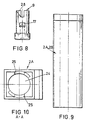
- Figures 8, 13 and 16 show in greater detail, the release ramps, that is to say, the second ramps or lower ramps 28 provided on cover 9 which must remain attached to the lower mouth at the second end of the conventional second telescopic body 2, as in the one represented by the invention, referenced with 2A.
- Figure 9 shows that, on the contrary to the conventional second telescopic body 2, the second telescopic body 2A does not present conventional windows, consequently remaining totally tight.
- ramps 25 are delimited by the material of telescopic body 2A, in such a manner that, they form in cross section, the segments of a circular crown which is concentric to the circle presented by the cross section of said cavity 24.
- Figure 2 represents the same elements as figure 1, with the exception of the second telescopic body which is to be found laterally closed to the exterior.
- the second telescopic body 2B has windows 18 (or recesses which do not completely penetrate the wall of the telescopic body), arranged contrary to the position occupied by windows 18 of the second telescopic body according to embodiment 2A, consequently being arranged on the walls of second telescopic body 2B on which the recesses 32 are not present, to avoid interference with the grooves 31. Consequently, for the attachment of cover 9 on telescopic body 2B, according to what may be appreciated in figure 13, attachment projections 17 of cover 9 are also arranged on walls adjacent to those which present the release ramps or lower ramps 28.
- the axial cavity 24 is cylindrical all throughout body 2B.
- first telescopic body 1 For the assembly of the telescopic mechanism which comprises the second telescopic body according to embodiment 2A, the conventional first telescopic body 1 provided with chamfers 30 is used, which is represented in figures 4 and 14, whilst, when dealing with second telescopic body 2B, first telescopic body 1A may be indistinctly used, represented in figures 5 and 15 and which does not present said chamfers.
- second telescopic body 2A striker 3 release spring 8 and cover 9 are assembled on the second telescopic body 2A. Subsequently, legs 7 surrounded by the recovery spring 5 of first telescopic body 1, 1A, already provided with the piezoelectric elements as well as with the previously described angular part, are inserted through the upper base of second telesocpic body 2A, in such a manner, that the axial slot 6 remains aligned between the recesses 32.
- the second telescopic body 2B may be indistinctly joined to conventional first telescopic body 1, or to first telescopic body 1A represented in figures 5 and 15.
- first telescopic body 1A represented in figures 5 and 15.
- the first telescopic body 1A When the second telescopic body 2B and the first telescopic body 1A are assembled, the first telescopic body 1A, provided with recovery spring 5 and with the piezoelectric elements, is inserted first inside the second telescopic body 2B, in such a manner, that axial slot 6 of the first telescopic body 1A, remains aligned with grooves 31 of the second telescopic body 2B.
- the recovery spring 5 is progressively compressed.
- the striker 3 is inserted so that its diametrical projections 4 enter inside grooves 31 of body 2B.
- the release spring is introduced and finally the cover (9).
- the diametrical projections 4 of striker 3 enter inside axial groove 6 of the first telescopic body 1A.
- the second telescopic body is only provided with upper ramp 25 in each one of its opposed recesses 32, the lower ramp 28 and the side edges of said longitudinal recesses 32, being arranged on the cover 9B itself.
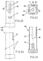
- the cylindrical hollow of cover 9B is referenced with number 33 (figure 23) and the same is housed and guided the cylindrical interior end of the first telescopic body 1.
- Reference 34 represents the coaxial spigot for guiding the release spring 8.
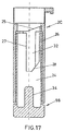
- figure 17 may be seen a sectioned longitudinal elevation view of the second telescopic body 2C and its lower cover 9B after being coupled, by means of the teeth 17 being introduced inside the corresponding windows 18.
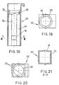
- the recovery ramps may be observed in figure 20, that is to say, the first ramps or upper ramps 25, as well as axial cavity 24 through which the cylindrical part of the interior upper body 1 is introduced.
- the seating surface of helicoidal spring 5 which assists the telescopic assembly is referenced with number 35.
- the second telescopic body is referenced generally with number 2D and it may be observed that its section corresponds with representation in figure 21, throughout all its length.
- cover 9A is coupled and, through its upper mouth, the detachable and independent part, carrier of a quadrangular neck 37, said neck being provided with teeth 28 for its interlocking with the windows 39 of the main portion of said second telescopic body 2D, similar to the interlocking of cover 9A.
- first ramps 25 and the vertical sections or guides 26 and 27 of longitudinal recesses 32, are performed on neck 37 of said upper detachable part 36.
- the second ramps 28 are to be found on the upper edge of lower cover 9A.
- the second telescopic body is referenced generally with 2E, having a detachable upper part 40 which is locked to the rest of the second telescopic body in like manner as described in relation to the embodiment of figures 26 through 28, though in this case, the neck, carrier of teeth 38, is of very short length since it only includes the first ramps or upper ramps 25.
- the rest of the second telescopic body 2E made up of one single part, since it is not necessary that the lower part be also detachable, includes the seconds ramps or lower ramps 28 and the guides or vertical edges 26 and 27 of the longitudinal recesses for activation on the striker.
Landscapes
- Engineering & Computer Science (AREA)
- Chemical & Material Sciences (AREA)
- Combustion & Propulsion (AREA)
- Mechanical Engineering (AREA)
- General Engineering & Computer Science (AREA)
- Lighters Containing Fuel (AREA)
Abstract
Description
- 1 -
- First telescopic body according to a conventional embodiment; which can also be used in the mechanism of the instant invention
- 1A -
- First telescopic body according to an embodiment of the invention.
- 2 -
- Second telescopic body according to a conventional embodiment.
- 2A-2E-
- Second telescopic body, or exterior telescopic body, according to different embodiments.
- 3 -
- Conventional striker.
- 4 -
- Conventional diametrical projections of the striker.
- 5 -
- Conventional recovery spring.
- 6 -
- Longitudinal slots of interior
telescopic body 1. - 7 -
- Longitudinal legs of interior
telescopic body 1. - 8 -
- Release spring.
- 9-9B-
- Closing cover of the lower mouth of the
telescopic body 2. - 10 -
- Upper recovery ramps, or first ramp.
- 11 -
- Vertical guiding section.
- 12 -
- Lower release ramp, or second ramp.
- 13 -
- Vertical guiding section.
- 14 -
- Anvil.
- 15 -
- First electrode.
- 16 -
- Pushbutton.
- 17 -
- Projection of the cover.
- 18 -
- Complementary windows of exterior body.
- 19 -
- Angular part, integral with interior
telescopic body 1. - 20 -
- Opening cam of the gas valve.
- 21 -
- Gas valve.
- 22 -
- Second lighting electrode.
- 23 -
- Lighter shell.
- 24 -
- Axial cavity of the second telescopic body.
- 25 -
- Upper or first ramp of the recesses for activation and guiding of the striker.
- 26 -
- Vertical edge or paraxial guide of the recesses
- 27 -
- Vertical edge or paraxial guide of the recesses
- 28 -
- Lower or second ramp of the hollows
- 29 -
- Side notches of
legs 7. - 30 -
- Chamfers of the free end the
legs 7. - 31 -
- Grooves of second
telescopic body 2B. - 32 -
- Recesses for activation and guiding of the striker.
- 33 -
- Cylindrical hollow of the cover.
- 34 -
- Coaxial spigot of the cover.
- 35 -
- Seating surface of
spring 5. - 36 -
- Upper detachable part of second
telescopic body 2D. - 37 -
- Neck of
upper part 36. - 38 -
- Teeth.
- 39 -
- Window.
- 40 -
- Upper detachable part of second
telescopic body 2E.
Claims (15)
- A piezoelectric mechanism which comprises:the striker (3) being axially guided by a paraxial slot (6) which divides the first end of the first telescopic body (1, 1A) into two legs (7), in which the projections (4) of the striker (3) play, said legs (7) being each provided with side notches (29) for the retention of said projections (4),a first telescopic body (1, 1A), a first end of which is partially inserted into a first end of a second telescopic body (2A-2E), said second telescopic body comprising said first end through which is inserted said first end of said first telescopic body (1, 1A), and a second end, axially opposed to said first end,a first spring (5) which keeps said first telescopic body (1, 1A) separated from said second telescopic body (2A-2E) at a predetermined distance, in the rest position of the mechanism,a piezoelectric element housed in the first telescopic body (1, 1A),a substantially cylindrical striker (3) with diametrically opposed side projections (4) housed in an axially moveable manner in an axial cavity (24) of the second telescopic body (2A-2E) and retained in a first position at a determined distance from the piezoelectric element by retention means associated to said telescopic bodies (1, 1A, 2A-2E),a second spring (8) for impelling the striker (3) against the piezoelectric element,releasing means of the striker (3) from its rest position, associated to telescopic bodies (1, 1A, 2A-2E), on application of a compressing force in the piezoelectric mechanism, said releasing means being arranged in a zone of the axial cavity (24) which presents a nonquadrangular cross section, said striker (3) retention means, functionally complementary to said releasing means, being provided in said telescopic bodies (1, 1A, 2A-2E),
characterized in that
the releasing means of the second telescopic body (2A-2E) in which the striker (3) is housed, are located inside said second telescopic body (2A-2E), and comprise two longitudinal recesses (32) in the interior wall of the axial cavity of said second telescopic body (2A-2E), not completely penetrating said wall, formed in inverted mirror image on opposite walls of said axial cavity (24),
the edges of each longitudinal recess (32) comprising:a first inclined and curved ramp (25) for guiding the projections (4) of the striker towards a rest position on a first end of said first ramp (25), at a first distance from the piezoelectric element,a first straight paraxial guide (26), with a first end, adjacent to the first end of the first ramp (25), for axially guiding the striker (3) towards a releasing position for the release on a second end, which is at a greater distance from the piezoelectric element than said first distance,a second straight paraxial guide (27) with a first end adjacent to a second end of the first ramp (25) opposite the first end of said first ramp (25), for axially guiding the striker (3), during the release against said piezoelectric element, towards said first ramp (25),and a second ramp (28), axially opposed to the first ramp (25) and inclined substantially in the same direction and with equal curvature to that of the first ramp (25), for causing the releasing of the striker (3) by actuation on the diametrical projections (4) of said striker (3), said second ramp (28) having a first end, adjacent to said second end of the first guide (26), and a second end, adjacent to a second end of the second guide (27), for guiding the striker (3) from said second end of the first guide (26) towards a position in which the striker (3) is axially more distanced from the first end of said second body (2A-2E), in said second end of said second guide (27), in which position the striker (3) is released in order to be impelled against the piezoelectric element;
and in that
the first ramp (25) is formed as an integral part of the second telescopic body (2A-2C) with the second ramp (28) being formed in an independent cover (9, 9A, 9B) inserted into the second end of the second telescopic body (2A, 2B, 2C), or the second ramp (28) is formed as an integral part of the second telescopic body (2E) with the first ramp being formed on an independent portion (40) arranged at the first end of the second telescopic body. - Piezoelectric mechanism, according to claim 1, characterized in that said axial cavity (24) comprises a first cylindrical section which extends from the first end of the second telescopic body (2A) up to at least the transversal plane corresponding to the location of the second end of the second guide (27) of the recesses (32).
- Piezoelectric mechanism, according to claim 2, characterized in that the axial cavity (24) presents a second section with quadrangular cross section, from said transversal plane up to said second end of the second telescopic body (2A, 2B).
- Piezoelectric mechanism, according to claim 3, characterized in that said quadrangular cross section presents diagonals which are longer than the diameters of said first cylindrical section, sufficiently long to form a passage through which the diametrical projections (4) of the striker (3) are guided, from said second end of the second telescopic body (2A, 2B).
- Piezoelectric mechanism, according to claim 2, characterized in that the axial cavity (24) presents a second cylindrical section with circular cross section, from said transversal plane up to the second end of the second telescopic body (2B).
- Piezoelectric mechanism, according to claim 5, characterized in that the diameter of said second cylindrical section is greater than the diameter of said first cylindrical section of said axial cavity (24).
- Piezoelectric mechanism, according to any of claims 1 through 6, characterized in that the second telescopic body (2B) presents two grooves (31), in central wall sections, which extend from the second end of the second telescopic body (2B) up into the respective recess (32).
- Piezoelectric mechanism, according to claim 1, characterized in that said second ramps (28) are provided on a part made up of a cover (9) inserted into the second end of the second telescopic body (2A, 2B), in the axial cavity (24), the cross section of said axial cavity (24) being complementary with the exterior cross section of said cover (9).
- Piezoelectric mechanism, according to claim 7, characterized in that the surfaces of the free ends of said legs (7) are essentially flat.
- Piezoelectric mechanism, according to claim 1, characterized in that the first ramps (25) and/or the paraxial guides (26, 27) are established on an independent portion of the second telescopic body (2C, 2D, 2E), which is capable of connection with the rest of the second telescopic body.
- Piezoelectric mechanism, according to claim 10, characterized in that the paraxial guides (26, 27), jointly with the second ramps (28) are included in two opposed walls of said independent portion, said independent portion being a cover (9B) which closes the second end of the second telescopic body (2C), the cover being equipped with a tubular portion which penetrates through an opening at said second end and which is provided with two notches in the edge of two of its opposed side walls, the upper end of said cover (9B) practically reaching the second end of the first ramps (25).
- Piezoelectric mechanism, according to claim 10, characterized in that the second telescopic body (2D, 2E) has an upper part which is detachable and independent from a lower part, joining the same since it is provided with a tubular extension (37) which is introduced through an upper mouth of said lower part, equipped with mutual interlocking means (38, 39).
- Piezoelectric mechanism, according to claim 12, characterized in that it includes in two external opposed points of the side walls of said upper detachable part (36, 40), teeth (38) which are interlocked in corresponding windows (39) of the side walls of said lower part of the second telescopic body, or vice versa.
- Piezoelectric mechanism, according to any of the claims 12 or 13, characterized in that the upper and independent part (36) of the second telescopic body (2D), includes the first ramps (25) and the paraxial guides (26, 27), its internal mouth practically reaching the edge of the cover (9A) which closes the second end of the second telescopic body (2D), equipped with a penetrating tubular portion which is provided with two notches in the edge of two of its opposed sides, establishing the second ramps (28).
- Piezoelectric mechanism, according to any of the claims 12 or 13, characterized in that the upper detachable part (40) of the second telescopic body (2E) includes the first ramps (25), its internal mouth practically reaching the initial end of the paraxial guides (26, 27) of said second telescopic body, in which also the second ramps (28) are established.
Applications Claiming Priority (5)
| Application Number | Priority Date | Filing Date | Title |
|---|---|---|---|
| ES9502394 | 1995-12-04 | ||
| ES09502394A ES2116204B1 (en) | 1995-12-04 | 1995-12-04 | PIEZOELECTRIC MECHANISM FOR GAS LIGHTERS WITH TELESCOPIC BODY CLOSED TO THE EXTERIOR. |
| ES9601237 | 1996-06-04 | ||
| ES09601237A ES2120364B1 (en) | 1995-12-04 | 1996-06-04 | IMPROVEMENTS INTRODUCED IN PATENT INVENTION N. P-9502394/1, BY: PIEZOELECTRIC MECHANISM FOR GAS LIGHTERS WITH TELESCOPIC BODY CLOSED TO THE EXTERIOR. |
| PCT/ES1996/000233 WO1997021255A1 (en) | 1995-12-04 | 1996-12-04 | Piezoelectric mechanism for gas lighters with externally closed telescopic body |
Publications (2)
| Publication Number | Publication Date |
|---|---|
| EP0821418A1 EP0821418A1 (en) | 1998-01-28 |
| EP0821418B1 true EP0821418B1 (en) | 2003-03-12 |
Family
ID=26154928
Family Applications (1)
| Application Number | Title | Priority Date | Filing Date |
|---|---|---|---|
| EP96940664A Expired - Lifetime EP0821418B1 (en) | 1995-12-04 | 1996-12-04 | Piezoelectric mechanism for gas lighters with externally closed telescopic body |
Country Status (7)
| Country | Link |
|---|---|
| US (1) | US5927962A (en) |
| EP (1) | EP0821418B1 (en) |
| JP (1) | JP3388755B2 (en) |
| AT (1) | ATE234510T1 (en) |
| AU (1) | AU1067397A (en) |
| DE (1) | DE69626638T2 (en) |
| WO (1) | WO1997021255A1 (en) |
Families Citing this family (4)
| Publication number | Priority date | Publication date | Assignee | Title |
|---|---|---|---|---|
| JP3730481B2 (en) * | 2000-06-02 | 2006-01-05 | 株式会社東海 | Ignition operation mechanism of piezoelectric ignition type lighter |
| US6765338B2 (en) | 2001-05-29 | 2004-07-20 | Bic Corporation | Child-resistant piezoelectric lighter |
| US6856074B2 (en) * | 2002-03-01 | 2005-02-15 | Bic Corporation | Piezoelectric ignition mechanism |
| CN111678169A (en) * | 2020-07-16 | 2020-09-18 | 中国船舶重工集团公司第七0三研究所 | An ignition device for improving the service cycle of oil-fired boilers |
Family Cites Families (25)
| Publication number | Priority date | Publication date | Assignee | Title |
|---|---|---|---|---|
| DE1629890B2 (en) * | 1967-02-11 | 1973-05-03 | Robert Bosch Gmbh, 7000 Stuttgart | IGNITION DEVICE FOR IGNITION OF COMBUSTIBLE GASES |
| DE1629892A1 (en) * | 1967-02-22 | 1971-03-11 | Bosch Gmbh Robert | Piezoelectric ignition device for igniting flammable gases |
| NL144382B (en) * | 1967-08-03 | 1974-12-16 | Mansei Kogyo Kk | CIGARETTE LIGHTER WITH PIEZO ELECTRICAL ELEMENTS. |
| GB1363570A (en) * | 1971-04-02 | 1974-08-14 | Murata Manufacturing Co | Piezoelectric igniter |
| FR2193955B1 (en) * | 1972-07-28 | 1975-03-07 | Genoud & Cie Ets | |
| AR205244A1 (en) * | 1972-09-07 | 1976-04-21 | Matsushita Electric Industrial Co Ltd | HIGH VOLTAGE GENERATOR DEVICE |
| GB1415003A (en) * | 1972-10-18 | 1975-11-26 | Matsushita Electric Industrial Co Ltd | Voltage generating arrangements |
| IT1023732B (en) * | 1973-05-14 | 1978-05-30 | Braun Ag | PIEZOELECTRIC IGNITION DEVICE FOR CIGAR LIGHTERS AND MORE |
| DE2335058A1 (en) * | 1973-07-10 | 1975-01-30 | Braun Ag | PIEZOZUENDER |
| US4015152A (en) * | 1974-08-12 | 1977-03-29 | Braun Aktiengesellschaft | Impact mechanism for piezoelectric transducers |
| DE2626515C3 (en) * | 1975-06-19 | 1978-06-22 | Matsushita Electric Industrial Co., Ltd., Kadoma, Osaka (Japan) | High voltage generator |
| GB1554332A (en) * | 1976-06-10 | 1979-10-17 | Matsushita Electric Industrial Co Ltd | High voltage generating device |
| FR2465161A1 (en) * | 1979-09-14 | 1981-03-20 | Cricket Sa | GAS LIGHTER |
| FR2498740B1 (en) * | 1981-01-23 | 1987-07-03 | Rv Const Elect | PIEZOELECTRIC IGNITER OF THE PERCUSSION TYPE AND PUSH BUTTON |
| US4608508A (en) * | 1984-08-31 | 1986-08-26 | Intermatch S.A. | Piezoelectric igniter, especially for a cigarette lighter or the like |
| JPH0335975Y2 (en) * | 1987-05-20 | 1991-07-30 | ||
| EP0312627B1 (en) * | 1987-10-21 | 1990-11-28 | Tokai Corporation | Gaslighter equipped with a safety lock |
| ES2014189A6 (en) * | 1989-08-02 | 1990-06-16 | Laforest Sa | Piezoelectric mechanism for gas lighters |
| JPH0492142U (en) * | 1990-11-30 | 1992-08-11 | ||
| CH683455A5 (en) * | 1991-03-13 | 1994-03-15 | Laforest Bic Sa | A piezoelectric mechanism for gas lighters. |
| ES2026089A6 (en) * | 1991-03-13 | 1992-04-01 | Laforest Bic Sa | Piezoelectric mechanism for gas lighters |
| ES2032187A6 (en) * | 1991-07-23 | 1993-01-01 | Laforest Bic Sa | Improvements to main patent No. 9100652 for piezoelectric mechanism for gas cigarette lighters |
| ES2046964A6 (en) * | 1991-11-11 | 1994-02-01 | Laforest Bic Sa | Improvements introduced in the subject of main patent num. 8902741 for: Piezoelectric mechanism for gas lighters |
| JP2784977B2 (en) * | 1992-01-13 | 1998-08-13 | 株式会社東海 | Gas lighter with safety device |
| US5462432A (en) * | 1994-06-17 | 1995-10-31 | Kim; Jin K. | Gas lighter with ignition safety device |
-
1996
- 1996-12-04 US US08/875,791 patent/US5927962A/en not_active Expired - Lifetime
- 1996-12-04 JP JP52101097A patent/JP3388755B2/en not_active Expired - Lifetime
- 1996-12-04 AU AU10673/97A patent/AU1067397A/en not_active Abandoned
- 1996-12-04 EP EP96940664A patent/EP0821418B1/en not_active Expired - Lifetime
- 1996-12-04 AT AT96940664T patent/ATE234510T1/en not_active IP Right Cessation
- 1996-12-04 DE DE69626638T patent/DE69626638T2/en not_active Expired - Lifetime
- 1996-12-04 WO PCT/ES1996/000233 patent/WO1997021255A1/en not_active Ceased
Also Published As
| Publication number | Publication date |
|---|---|
| DE69626638T2 (en) | 2003-12-18 |
| ATE234510T1 (en) | 2003-03-15 |
| WO1997021255A1 (en) | 1997-06-12 |
| JPH11500216A (en) | 1999-01-06 |
| AU1067397A (en) | 1997-06-27 |
| DE69626638D1 (en) | 2003-04-17 |
| US5927962A (en) | 1999-07-27 |
| EP0821418A1 (en) | 1998-01-28 |
| JP3388755B2 (en) | 2003-03-24 |
Similar Documents
| Publication | Publication Date | Title |
|---|---|---|
| US5262697A (en) | Piezoelectric mechanism for gas lighters | |
| US5854530A (en) | Piezoelectric lighter which has a higher level of difficulty for operation | |
| JPH0370914A (en) | Piezoelectric mechanism of gas lighter | |
| US5927962A (en) | Piezoelectric mechanism for gas lighters with externally closed telescopic body | |
| EP1029373B1 (en) | Selectively actuatable piezoelectric ignition mechanism | |
| RU2215240C2 (en) | Infant-proof lighter | |
| CN100520183C (en) | Child-resistant piezoelectric lighter | |
| US6106277A (en) | Safety arrangement of piezoelectric unit for piezoelectric lighter | |
| US7397170B2 (en) | Piezoelectric mechanism for generating discharge voltage | |
| EP0732545B1 (en) | Piezoelectric gas igniter | |
| KR100962762B1 (en) | Piezoelectric igniter | |
| US4291626A (en) | Assembly of piezoelectric element unit and sheet metal mount for ignition device | |
| KR970006437B1 (en) | switch | |
| JP3106805U (en) | Rivet fastening device | |
| JP3773246B2 (en) | Gas lighter | |
| EP0172973A1 (en) | Piezoelectric igniter mechanism | |
| IE55607B1 (en) | Piezoelectric igniter mechanism | |
| KR200217910Y1 (en) | Lighter ignition_ | |
| TH38212A (en) | Lighter to keep children playing. | |
| JP2002048340A (en) | Supporting structure of operation cap of slide operation lighter | |
| BE535706A (en) | ||
| HK1024337B (en) | Piezoelectric lighter which has a higher level of difficulty for operation | |
| HK1081328B (en) | Piezoelectric ignition mechanism |
Legal Events
| Date | Code | Title | Description |
|---|---|---|---|
| PUAI | Public reference made under article 153(3) epc to a published international application that has entered the european phase |
Free format text: ORIGINAL CODE: 0009012 |
|
| 17P | Request for examination filed |
Effective date: 19970806 |
|
| AK | Designated contracting states |
Kind code of ref document: A1 Designated state(s): AT BE CH DE DK ES FI FR GB GR IE IT LI LU MC NL PT SE |
|
| 17Q | First examination report despatched |
Effective date: 19991025 |
|
| GRAG | Despatch of communication of intention to grant |
Free format text: ORIGINAL CODE: EPIDOS AGRA |
|
| GRAG | Despatch of communication of intention to grant |
Free format text: ORIGINAL CODE: EPIDOS AGRA |
|
| GRAH | Despatch of communication of intention to grant a patent |
Free format text: ORIGINAL CODE: EPIDOS IGRA |
|
| GRAH | Despatch of communication of intention to grant a patent |
Free format text: ORIGINAL CODE: EPIDOS IGRA |
|
| GRAA | (expected) grant |
Free format text: ORIGINAL CODE: 0009210 |
|
| AK | Designated contracting states |
Designated state(s): AT BE CH DE DK ES FI FR GB GR IE IT LI LU MC NL PT SE |
|
| PG25 | Lapsed in a contracting state [announced via postgrant information from national office to epo] |
Ref country code: NL Free format text: LAPSE BECAUSE OF FAILURE TO SUBMIT A TRANSLATION OF THE DESCRIPTION OR TO PAY THE FEE WITHIN THE PRESCRIBED TIME-LIMIT Effective date: 20030312 Ref country code: LI Free format text: LAPSE BECAUSE OF FAILURE TO SUBMIT A TRANSLATION OF THE DESCRIPTION OR TO PAY THE FEE WITHIN THE PRESCRIBED TIME-LIMIT Effective date: 20030312 Ref country code: IT Free format text: LAPSE BECAUSE OF FAILURE TO SUBMIT A TRANSLATION OF THE DESCRIPTION OR TO PAY THE FEE WITHIN THE PRESCRIBED TIME-LIMIT;WARNING: LAPSES OF ITALIAN PATENTS WITH EFFECTIVE DATE BEFORE 2007 MAY HAVE OCCURRED AT ANY TIME BEFORE 2007. THE CORRECT EFFECTIVE DATE MAY BE DIFFERENT FROM THE ONE RECORDED. Effective date: 20030312 Ref country code: GR Free format text: LAPSE BECAUSE OF FAILURE TO SUBMIT A TRANSLATION OF THE DESCRIPTION OR TO PAY THE FEE WITHIN THE PRESCRIBED TIME-LIMIT Effective date: 20030312 Ref country code: FR Free format text: LAPSE BECAUSE OF FAILURE TO SUBMIT A TRANSLATION OF THE DESCRIPTION OR TO PAY THE FEE WITHIN THE PRESCRIBED TIME-LIMIT Effective date: 20030312 Ref country code: FI Free format text: LAPSE BECAUSE OF FAILURE TO SUBMIT A TRANSLATION OF THE DESCRIPTION OR TO PAY THE FEE WITHIN THE PRESCRIBED TIME-LIMIT Effective date: 20030312 Ref country code: CH Free format text: LAPSE BECAUSE OF FAILURE TO SUBMIT A TRANSLATION OF THE DESCRIPTION OR TO PAY THE FEE WITHIN THE PRESCRIBED TIME-LIMIT Effective date: 20030312 Ref country code: BE Free format text: LAPSE BECAUSE OF FAILURE TO SUBMIT A TRANSLATION OF THE DESCRIPTION OR TO PAY THE FEE WITHIN THE PRESCRIBED TIME-LIMIT Effective date: 20030312 Ref country code: AT Free format text: LAPSE BECAUSE OF FAILURE TO SUBMIT A TRANSLATION OF THE DESCRIPTION OR TO PAY THE FEE WITHIN THE PRESCRIBED TIME-LIMIT Effective date: 20030312 |
|
| REG | Reference to a national code |
Ref country code: GB Ref legal event code: FG4D |
|
| REG | Reference to a national code |
Ref country code: CH Ref legal event code: EP |
|
| REG | Reference to a national code |
Ref country code: IE Ref legal event code: FG4D |
|
| REF | Corresponds to: |
Ref document number: 69626638 Country of ref document: DE Date of ref document: 20030417 Kind code of ref document: P |
|
| PG25 | Lapsed in a contracting state [announced via postgrant information from national office to epo] |
Ref country code: SE Free format text: LAPSE BECAUSE OF FAILURE TO SUBMIT A TRANSLATION OF THE DESCRIPTION OR TO PAY THE FEE WITHIN THE PRESCRIBED TIME-LIMIT Effective date: 20030612 Ref country code: PT Free format text: LAPSE BECAUSE OF FAILURE TO SUBMIT A TRANSLATION OF THE DESCRIPTION OR TO PAY THE FEE WITHIN THE PRESCRIBED TIME-LIMIT Effective date: 20030612 Ref country code: DK Free format text: LAPSE BECAUSE OF FAILURE TO SUBMIT A TRANSLATION OF THE DESCRIPTION OR TO PAY THE FEE WITHIN THE PRESCRIBED TIME-LIMIT Effective date: 20030612 |
|
| NLV1 | Nl: lapsed or annulled due to failure to fulfill the requirements of art. 29p and 29m of the patents act | ||
| REG | Reference to a national code |
Ref country code: CH Ref legal event code: PL |
|
| PG25 | Lapsed in a contracting state [announced via postgrant information from national office to epo] |
Ref country code: ES Free format text: LAPSE BECAUSE OF FAILURE TO SUBMIT A TRANSLATION OF THE DESCRIPTION OR TO PAY THE FEE WITHIN THE PRESCRIBED TIME-LIMIT Effective date: 20030930 |
|
| PG25 | Lapsed in a contracting state [announced via postgrant information from national office to epo] |
Ref country code: LU Free format text: LAPSE BECAUSE OF NON-PAYMENT OF DUE FEES Effective date: 20031204 Ref country code: IE Free format text: LAPSE BECAUSE OF NON-PAYMENT OF DUE FEES Effective date: 20031204 Ref country code: GB Free format text: LAPSE BECAUSE OF NON-PAYMENT OF DUE FEES Effective date: 20031204 |
|
| PG25 | Lapsed in a contracting state [announced via postgrant information from national office to epo] |
Ref country code: MC Free format text: LAPSE BECAUSE OF NON-PAYMENT OF DUE FEES Effective date: 20031231 |
|
| PLBE | No opposition filed within time limit |
Free format text: ORIGINAL CODE: 0009261 |
|
| STAA | Information on the status of an ep patent application or granted ep patent |
Free format text: STATUS: NO OPPOSITION FILED WITHIN TIME LIMIT |
|
| EN | Fr: translation not filed | ||
| 26N | No opposition filed |
Effective date: 20031215 |
|
| GBPC | Gb: european patent ceased through non-payment of renewal fee |
Effective date: 20031204 |
|
| REG | Reference to a national code |
Ref country code: IE Ref legal event code: MM4A |
|
| PGFP | Annual fee paid to national office [announced via postgrant information from national office to epo] |
Ref country code: DE Payment date: 20151223 Year of fee payment: 20 |
|
| REG | Reference to a national code |
Ref country code: DE Ref legal event code: R071 Ref document number: 69626638 Country of ref document: DE |