EP0821233A2 - Volume independent diagnostic test element and method to assay analytes using it - Google Patents
Volume independent diagnostic test element and method to assay analytes using it Download PDFInfo
- Publication number
- EP0821233A2 EP0821233A2 EP97112360A EP97112360A EP0821233A2 EP 0821233 A2 EP0821233 A2 EP 0821233A2 EP 97112360 A EP97112360 A EP 97112360A EP 97112360 A EP97112360 A EP 97112360A EP 0821233 A2 EP0821233 A2 EP 0821233A2
- Authority
- EP
- European Patent Office
- Prior art keywords
- layer
- diagnostic test
- test carrier
- detection
- network
- Prior art date
- Legal status (The legal status is an assumption and is not a legal conclusion. Google has not performed a legal analysis and makes no representation as to the accuracy of the status listed.)
- Granted
Links
Images


Classifications
-
- G—PHYSICS
- G01—MEASURING; TESTING
- G01N—INVESTIGATING OR ANALYSING MATERIALS BY DETERMINING THEIR CHEMICAL OR PHYSICAL PROPERTIES
- G01N33/00—Investigating or analysing materials by specific methods not covered by groups G01N1/00 - G01N31/00
- G01N33/48—Biological material, e.g. blood, urine; Haemocytometers
- G01N33/50—Chemical analysis of biological material, e.g. blood, urine; Testing involving biospecific ligand binding methods; Immunological testing
- G01N33/52—Use of compounds or compositions for colorimetric, spectrophotometric or fluorometric investigation, e.g. use of reagent paper and including single- and multilayer analytical elements
- G01N33/521—Single-layer analytical elements
-
- G—PHYSICS
- G01—MEASURING; TESTING
- G01N—INVESTIGATING OR ANALYSING MATERIALS BY DETERMINING THEIR CHEMICAL OR PHYSICAL PROPERTIES
- G01N33/00—Investigating or analysing materials by specific methods not covered by groups G01N1/00 - G01N31/00
- G01N33/48—Biological material, e.g. blood, urine; Haemocytometers
- G01N33/50—Chemical analysis of biological material, e.g. blood, urine; Testing involving biospecific ligand binding methods; Immunological testing
- G01N33/53—Immunoassay; Biospecific binding assay; Materials therefor
-
- Y—GENERAL TAGGING OF NEW TECHNOLOGICAL DEVELOPMENTS; GENERAL TAGGING OF CROSS-SECTIONAL TECHNOLOGIES SPANNING OVER SEVERAL SECTIONS OF THE IPC; TECHNICAL SUBJECTS COVERED BY FORMER USPC CROSS-REFERENCE ART COLLECTIONS [XRACs] AND DIGESTS
- Y10—TECHNICAL SUBJECTS COVERED BY FORMER USPC
- Y10T—TECHNICAL SUBJECTS COVERED BY FORMER US CLASSIFICATION
- Y10T436/00—Chemistry: analytical and immunological testing
- Y10T436/25—Chemistry: analytical and immunological testing including sample preparation
- Y10T436/25375—Liberation or purification of sample or separation of material from a sample [e.g., filtering, centrifuging, etc.]
Definitions
- the invention relates to a diagnostic test carrier containing a base layer with a or several arranged thereon required for the determination of analyte in liquid sample Detection layers containing reagents and one covering the detection layers Network that is larger than the detection layers and that is attached to the base layer is.
- the invention also relates to the use of this diagnostic test carrier for Determination of analyte in a liquid and a method for the determination of analyte in liquid sample with the aid of a diagnostic test carrier according to the invention.
- reagents are on or in corresponding layers of a solid test carrier which is brought into contact with the sample.
- the reaction of liquid sample and reagents leads to a detectable signal, especially a color change, which is visual or can be evaluated with the aid of a device, usually by reflection photometry.
- Test carriers are often designed as test strips, which essentially consist of an elongated Base layer made of plastic material and attached detection layers as test fields consist. However, test carriers are also known, which are square or rectangular platelets are designed.
- Test carriers of the type described at the outset are, for example, from the German patent specification 21 18 455 known.
- diagnostic test carriers for the detection of analytes in Liquids described consist of a base layer and at least one of the detection reagents containing detection layer, the surface of which does not lie on the base layer is provided with a cover layer.
- the top layer can consist of a fine mesh Network in the form of a fabric, knitted fabric or fleece. Plastic fabric are given as preferred networks for a quick wetting of the detection layer to achieve with sample liquid and to avoid disturbing chromatography effects.
- Such a diagnostic test carrier is used to detect an analyte in a liquid immersed in an appropriate liquid, preferably urine.
- the detection layer comes into contact with a very large excess of liquid that is not from that Test carrier can be included. Depending on the duration of contact of the detection layer however, different color intensities can be observed with the liquid to be examined will. Longer contact times usually lead to more positive results. A correct quantitative analyte determination is therefore not possible.
- test carriers with the lowest possible volume requirements are therefore the goal of diverse current developments.
- test carriers do not only have to be included very small sample volumes of about 3 ⁇ l give correct measured values, but they have to work reliably even with relatively large sample volumes of around 15-20 ⁇ l Hold sample liquid.
- liquid leakage from the test carrier hygienic problems can occur, for example when there is a potentially infectious problem Foreign blood is measured or if the test carrier is to be measured using equipment and then there is a risk of contamination of the measuring device. This goal is known of the patent applicant has not yet been achieved in a satisfactory manner in a simple manner been.
- the object of the present invention is therefore to provide a diagnostic test carrier for quantitative Determination of analyte in a liquid to provide an undosed one Sample liquid amount can be abandoned. Sample volumes from 3 ⁇ l should be sufficient. However, a sample liquid excess should not become time-dependent false positive Lead results. In addition, excess sample liquid should not be hygienic Problems and the test carrier should be as easy to manufacture as possible.
- the object of the invention is namely a diagnostic test carrier with a base layer and a detection layer arranged thereon, which is used to determine analyte in liquid Contains required reagents.
- the detection layer is covered by a network, which is larger than the detection layer and which is outside the detection layer on the Base layer is attached.
- the network of the diagnostic test carrier according to the invention is hydrophilic, but not capillary-active on its own. Beyond that which extends beyond the detection layers Areas of the network is an inert cover made of liquid impermeable to samples Material arranged so that on the area of the network that is above a detection layer an area for sample application remains free.
- the invention also relates to the use of such a diagnostic test carrier for the determination of analyte in a liquid.
- a procedure for Determination of analyte in liquid sample with the help of such a diagnostic test carrier Object of the invention in which sample liquid is applied to the sample application point becomes.
- the network carries excess liquid from the detection layer to the over the Detection layer protruding area of the network, whereupon the detection layer is observed for signal formation.
- the signal formation is a measure of the presence or amount of analyte in the examined liquid sample.
- the network of the diagnostic test carrier according to the invention should not itself be capillary-active or be absorbent so that the sample liquid is as complete as possible for the detection layer is available.
- Networks that have proven to be suitable are those that are vertical Immersion in water allows the water to rise in the network by less than 2 mm.
- Coarse-mesh monofilament fabrics are preferably used as the network are hydrophilic.
- the tissue material itself can be hydrophilic or, for example can be made hydrophilic by treatment with wetting agent.
- a particularly preferred Mesh material is polyester, the mesh made of this material then Treated wetting agent is used.
- the thickness of the network must be such that the cover and the underlying layer are at such a distance from each other that remaining Liquid over the saturated detection layer and in the filled mesh of the Network sucked up by capillary force in the area under the cover and from the Sample application is carried away.
- the thickness of the network for this is 50 to 400 ⁇ m advantageous.
- the network must have a sufficiently large mesh size so that liquid through the Network reaches the detection layer. Due to the nature of the network Liquid does not spread horizontally in the mesh over the mesh surface, but flows vertically through the network to the detection layer.
- a diagnostic test carrier in particular, come for the base layer materials in question that do not absorb the liquids to be examined.
- plastic films being made of, for example Polystyrene, polyvinyl chloride, polyester, polycarbonate or polyamide are particularly preferred.
- absorbent materials such as wood, paper or cardboard impregnated with water-repellent agents or coated with a waterproof film, with silicones or hard fats as water repellents and, for example, as film formers Nitrocellulose or cellulose acetate can be used.
- Carrier materials are suitable for metal foils or glass.
- a detection layer it is necessary to use such materials which are able to contain the liquid to be examined with the ingredients contained therein record, tape.
- absorbent materials such as nonwovens, Fabrics, knitted fabrics, membranes or other porous plastic materials or swellable Materials such as gelatin or dispersion films used as layer materials can.
- the materials in question for the detection layer must of course can also carry reagents necessary for the detection of the analyte to be determined are. In the simplest case there are all necessary for the detection of the analyte Reagents on or in a layer.
- detection layer is intended to encompass both cases in which the reagents either only in or on one layer or in two or more as above described, arranged layers.
- the detection layer can also contain a layer that consists of plasma or serum Is able to separate whole blood, such as a glass fiber fleece, such as it is is known from EP-B-0 045 476.
- a layer that consists of plasma or serum Is able to separate whole blood such as a glass fiber fleece, such as it is is known from EP-B-0 045 476.
- One or more such separation layers can be over one or several layers that carry detection reagents.
- Such a structure should also be included in the term "detection layer”.
- Preferred materials for the detection layer are papers or porous plastic materials, like membranes. Of these, asymmetrical porous membranes are particularly preferred are advantageously arranged so that the sample liquid to be examined on the large pore side of the membrane is abandoned and the determination of the analyte from the fine pore Side of the membrane.
- the porous membrane materials are polyamide, Polyvinylidene difluoride, polyether sulfone or polysulfone membranes are particularly preferred.
- Polyamide 66 membranes and hydrophilized ones are particularly suitable asymmetric polysulfone membranes.
- the reagents for the determination of the to be detected As a rule, analytes are introduced into the materials mentioned above by impregnation or applied by coating on one side. With asymmetrical coating Membranes are advantageously coated on the fine-pored side.
- Suitable film formers are preferably organic plastics, such as Polyvinyl esters, polyvinyl acetates, polyacrylic esters, polymethacrylic acid, polyacrylamides, polyamides, Polystyrene, copolymers, for example of butadiene and styrene or of maleic acid esters and vinyl acetate or other film-forming, natural and synthetic organic Polymers and mixtures thereof in the form of aqueous dispersions.
- organic plastics such as Polyvinyl esters, polyvinyl acetates, polyacrylic esters, polymethacrylic acid, polyacrylamides, polyamides, Polystyrene, copolymers, for example of butadiene and styrene or of maleic acid esters and vinyl acetate or other film-forming, natural and synthetic organic Polymers and mixtures thereof in the form of aqueous dispersions.
- the dispersions can be spread on an underlayer to form an even layer, which after the Drying gives a waterproof film.
- the dry films have a thickness of 10 ⁇ m to 500 microns, preferably from 30 to 200 microns.
- the film can be used together with the base as a carrier be used or applied to another carrier for the detection reaction will.
- the reagents required for the detection reaction are usually can be added to the dispersion used to make the open films be advantageous if the film formed is impregnated with the reagents after its production becomes. Pre-impregnation of the fillers with the reagents is also possible. Which reagents can be used to determine a specific analyte known to the expert. This need not be explained in more detail here.
- a detection layer preferred according to the invention is a film layer, as described in WO-A-92 15 879.
- This layer is made from a dispersion or emulsion of a polymeric film former, which additionally in homogeneous distribution contains a pigment, a swelling agent and the detection reagent.
- a polymer film former are particularly suitable polyvinyl esters, polyvinyl acetates, polyacrylic esters, polymethacrylic acid, Polyvinylamides, polyamides and polystyrene.
- copolymers e.g. of butadiene, styrene or maleic acid esters. Titanium dioxide is one for pigment particularly suitable for the film.
- the swelling agent used is said to be particularly good Have swelling properties, particularly methyl vinyl ether maleic anhydride copolymer is recommended. Which reagents are used to determine a particular analyte are left to the specialist.
- a diagnostic test carrier according to the invention is very particularly preferred Test field used as a detection layer, which is composed of two layers.
- This test field comprises a transparent film, on which in this order a first and a second film layer are superimposed. It is essential that the transparent First layer in the moist state is significantly less light-scattering than that overlying second layer.
- the uncoated side of the transparent film is called Identifies the detection side and the side of the second layer that lies opposite the side with the second layer on top of the first is called the sample application side.
- the film layers are made from dispersions or emulsions of polymeric film formers.
- Dispersion film formers contain microscopic, in the carrier liquid (mostly water) insoluble polymer particles, which disperse in the finest distribution in the carrier liquid are. If the liquid is removed by evaporation during film formation, the approach Particles and eventually touch. Due to the large forces and a with the film formation associated with a gain in surface energy, the particles grow a largely closed film layer.
- an emulsion of the film former can be used, in which this is dissolved in a solvent. The dissolved polymer is emulsified in a carrier liquid that is not with the solvent is miscible.
- Particularly suitable polymers for such film formers are polyvinyl esters, polyvinyl acetates, Polyacrylic esters, polymethacrylic acid, polyvinylamides, polyamides and polystyrene.
- copolymers e.g. B. of butadiene, styrene or maleic acid suitable.
- the two film layers mentioned are located on a transparent film in the test field.
- Plastic foils which are impermeable to liquids are particularly suitable for this purpose are.
- Polycarbonate film has proven to be particularly preferred.
- the two layers of film can be produced from coating compositions which contain the same polymeric film former or they can be produced from coating compositions that contain different polymeric film formers.
- first shift Contains swelling agent and possibly a weakly light-scattering filler second layer a swelling agent and in any case at least one highly light-scattering pigment.
- second layer can also contain non-porous fillers and porous fillers such as Diatomaceous earth, contained in small quantities without becoming permeable to erythrocytes.
- a well swelling swelling agent that is, a substance that is ingested of water increases their volume
- the swelling properties should be so good that for a test where the speed the color formation - such as a glucose detection reaction - predominantly from the penetration of the sample liquid through the layer depends on the optically detectable Reaction is measurable after a maximum of one minute.
- a well swelling swelling agent that is, a substance that is ingested of water increases their volume
- the swelling properties should be so good that for a test where the speed the color formation - such as a glucose detection reaction - predominantly from the penetration of the sample liquid through the layer depends on the optically detectable Reaction is measurable after
- Diatomaceous earth is also known as diatomaceous earth. It is made from the silica scaffolds deposits of the diatom species, which are broken down in different places will.
- the preferred diatomaceous earth has an average particle diameter of 5-15 ⁇ m, these values being determined with a type 715 laser granulometer, which is distributed by the company Pabisch, Kunststoff, Federal Republic of Germany.
- the strongly light-scattering pigment portion of the second layer is at least 25% by weight, based on the dried and ready-to-use double layer of the test field. Since the weakly light-scattering fillers and the strong light-scattering pigments essential for the optical properties of the film layers are responsible, possess the first and the second film layer different fillers and pigments.
- the first film layer should either contain no fillers or fillers whose refractive index is close to the refractive index of water. Have proven to be particularly suitable for this Silicon dioxide, silicates and aluminum silicates have been proven. A sodium aluminum silicate with the Trade names Transpafill® is particularly preferred.
- the second layer should be very light-scattering. Ideally, that is Refractive index of the pigments in the second film layer is at least 2.5. Therefore, it is preferred Titanium dioxide used. Particles with an average diameter of about 0.2 to 0.8 ⁇ m have proven to be particularly advantageous. Easily processable titanium dioxide types in the anatase modification are very particularly preferred.
- Reagent systems for the detection of certain analytes by color formation are known to the person skilled in the art known. It is possible that all components of the reagent system are in one film layer are located. But it is also possible that the components of the reagent system both film layers are distributed. The color-forming reagent system is advantageously located at least in part in the first film layer.
- color formation is understood not only to mean the transition from white to color, but also any color change, of course those color changes which are associated with the greatest possible shift in the maximum absorption waveline ( ⁇ max ) are particularly preferred.
- both film layers are non-hemolyzing Contain wetting agents.
- Neutral that is, non-charged wetting agents are special for this suitable.
- N-Octanoyl-N-methyl-glucamide is very particularly preferred.
- the respective film layers in succession from a homogeneous dispersion of the above Components manufactured.
- the transparent film for the first film layer After applying the coating compound for the first film layer in a certain layer thickness the layer dried.
- the coating composition for the second layer is then applied to this layer also applied in a thin layer thickness and dried. After drying should the thickness of the first and second film layers together at most 0.2 mm, preferably at most 0.12 mm, particularly preferably a maximum of 0.08 mm.
- the dry one second film layer about 2 to 5 times thicker than the first.
- the test carrier according to the invention can have 1 detection layer. But he can also contain several detection layers arranged side by side. In the case of multiple detection layers can be the same or different, so that one and the same analyte in several detection layers next to each other or different analytes can be determined can be detected in a different detection layer. But it is also possible that there are several spatially separated reaction areas next to each other on a detection layer so that either the same analyte is repeated several times or different Analytes can be determined side by side in the same detection layer. In the latter case the material of the layer is the same except for the reagents for determining the analytes. In different reagents contain different reagents. Various Reaction areas can be touching or side by side lying areas that do not form a signal with analyte must be separated.
- the diagnostic test carrier that which covers the detection layer is Network larger than the detection layer below.
- the one over the detection layer protruding part of the network that is the part of the network that is not connected to the Detection layer in contact is outside the detection layer on the base layer attached directly or indirectly via spacers.
- the attachment can be according to the expert methods known from test carrier technology. For example, the attachment using hot melt adhesive or hardening cold adhesive.
- the attachment using hot melt adhesive or hardening cold adhesive.
- a one-off or screened adhesive advantageous because the capillary active liquid transport in this Case is particularly possible. Double-sided adhesive strips have also been found to be advantageous proven.
- Adhesive tapes are particularly suitable for processing proven with natural or synthetic rubber. It is particularly advantageous if that Means that are used to attach the network to the base layer, about the same thickness how the detection layer (s) has. It then serves as a kind of spacer around the network also outside the area of the detection layer (s) as a whole To keep the surface level.
- a network can cover all detection layers or several Networks are used.
- diagnostic test vehicle the detection layer, but at least the reaction areas, that is, reagent-bearing areas of the detection layer (s) that indicate signal formation can be observed and measured, visible through the base layer. This can be done achieved that the base layer is transparent. But it is also possible that the Base layer has a perforation from the detection layer or layers is covered. The detection layer or the detection layers are then through the perforation at least the reaction areas of the detection layers are visible.
- a detection layer is a hole through which the detection layer or a Reaction district is observable.
- the hole has a slightly smaller diameter than that smallest length extension of the detection layer, so that the detection layer outside the Hole rests on the base layer and can be attached there.
- the Detection layer by double-sided adhesive tapes arranged on both sides and that Network above the detection layer and its attachment to the base layer are sufficient fixed.
- the detection layer itself is also preferred by means of thin adhesive tape attached to the base course.
- reaction areas of a detection layer can also be seen through a hole be.
- the perforation of a diagnostic test carrier according to the invention can also consist of two or more holes exist that are used to determine analyte (one or more analytes) can be.
- Various detection layers can be arranged over the holes be or only a detection layer with several reaction areas, so that by 1 Hole a detection layer or a reaction area can be observed. It is also possible that several reaction zones can be observed through one hole.
- an inert cover over the network of the diagnostic test carrier according to the invention made of sample-impermeable, usually water-impermeable and non-absorbent Material arranged so that the area of the network is outside the detection layer is covered. Ideally, the cover also protrudes a little over the area of the Detection layer. In any case, a significant part of the network that the Detection layer covered, free. This free part of the network is called the sample application center designated.
- Plastic films have proven to be particularly advantageous as a cover. If cover and network have different colors, for example white and yellow or white and red, the position can be identified very clearly on the one to be examined Sample liquid to be added.
- one or more arrows can be printed on the cover be made clear in which direction, that is, with which end an inventive diagnostic test carrier is to be placed or pushed into a measuring device.
- a sample application point can be particularly easily covered by means of two band-shaped covers Plastic films can be reached covering a band-like area of the detection layer blanket network. If 2 or more sample application sites are provided 3 or more band-shaped plastic films are to be used.
- the cover Foils used are on the network and possibly on the base layer attached. Hot melt adhesives are suitable for such an attachment, preferably at certain points or are applied in a grid pattern on the base layer or the underside of the cover or Adhesive tapes if the foils are not self-adhesive. In any case, it is heading for make sure that a capillary gap remains under the cover, formed by the network, in the excess sample liquid is absorbed by a detection layer saturated with liquid can be.
- the sample application point is preferably located above the Punching in the base layer, through which a signal formation in the detection layer is observed can be.
- sample liquid on that of the detection layer abandoned side of the network is sample liquid on that of the detection layer abandoned side of the network, ideally so much that the through liquid entering the network completely saturates the detection layer.
- sample liquid body fluids such as blood, plasma, serum, urine, saliva come in particular etc. in question.
- Blood or liquids derived from blood, such as plasma or serum, as well as urine are particularly preferred sample liquids.
- Excess liquid is removed by the Network from the detection layer to the area that extends beyond the detection layer of the network. In the detection layer can then be determined in the presence of the Analyts a signal can be detected.
- Such a signal for a color change including both color formation, color loss and color change is also understood.
- the intensity of the color change is a measure of that Amount of analyte in the examined liquid sample. It can be done visually or with the help of a device, mostly evaluated quantitatively by reflection photometry.
- the sample is present, for example, visually or by reflectometry Measurement of several sub-areas of the detection layer determine that only part of the detection layer is moistened and therefore too little sample liquid has been applied has been.
- such a cover In addition to marking the sample application site, such a cover also supports the capillary forces, which lead excess fluid away from the detection layer cause. In addition, the cover leads to that of the detection layer excess liquid is protected from external contact and such liquid is not can easily drip off the test carrier.
- a great advantage of the diagnostic test carrier according to the invention is that none predetermined volume of a sample liquid must be applied to the test carrier. Excess liquid is, as already mentioned above, through the detection layer projecting network away from the detection layer. Because excess Liquid being drained away from the detection layer also becomes hygienic Taken into account. A drop of liquid from the test carrier or a contact of liquid, for example, with parts of a device in which the test carrier for apparatus Evaluation is reliably avoided. This is especially true when examining a very important one from blood or blood derived samples such as plasma or serum Aspect.
- the size of the area of the network that extends beyond the detection layer depends on that in practice largest sample volume to be expected, so that actually excess liquid from the detection layer can be removed. In this way, the presence is there signal intensity of an analyte regardless of the amount and the Duration of contact of the sample liquid with the detection layer.
- the color that follows Completion of the detection reaction usually within a few seconds to less Minutes, remains unchanged for the measurement. It is only through the The stability of the coloring system is determined, but not, for example, by the analyte Excess liquid diffuses into the detection layer. False positive results are also avoided and quantitative analyte determination is made possible.
- test carrier By covering parts of the network and thus marking the sample application site care is taken to ensure that liquid only reaches the optimal position on the Detection layer can reach. In combination with a detection layer that is little Absorbs liquid and still ensures intensive signal formation, it is ensured that reliable analyte determinations are possible even with very small sample volumes are. Because the test carrier according to the invention consists of only a few components, which are easy and quick to assemble, it is very inexpensive to manufacture.
- FIG. 1-23 Preferred embodiments of the diagnostic test carrier according to the invention are shown in FIG. 1-23 shown.
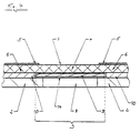
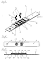
- FIG. 1 shows a perspective view of a diagnostic test carrier according to the invention with a sample application center.
- FIG. 2 shows a top view of the underside of a diagnostic test carrier according to the invention 1 with round perforations under the detection layer.
- FIG. 3 shows a cross section through a diagnostic test carrier according to the invention Fig. 1 along A-A.
- FIG. 4 shows an enlargement of part of the cross section from FIG. 3.
- FIG. 5 shows a perspective view of a diagnostic test carrier according to the invention with two sample application points.
- FIG. 6 shows a top view of the underside of a diagnostic test carrier according to the invention 5 with a perforation consisting of a round and rectangular hole under 2 separate detection layers.
- FIG. 7 shows a cross section through a diagnostic test carrier according to the invention Fig. 5 along A-A.
- FIG. 8 shows a perspective view of a diagnostic test carrier according to the invention with an extra large sample application point.
- FIG. 9 shows a top view of the underside of a diagnostic test carrier according to the invention 8 with a perforation consisting of a round and rectangular hole below an extra large detection layer.
- FIG. 10 shows a cross section through a diagnostic test carrier according to the invention Fig. 8 along A-A.
- FIG. 11 shows a perspective view of a diagnostic test carrier according to the invention with a sample application point over one of two detection layers.
- FIG. 12 shows a top view of the underside of a diagnostic test carrier according to the invention 11 with a perforation consisting of round and rectangular hole below two separate detection layers.
- FIG. 13 shows a cross section through a diagnostic test carrier according to the invention Fig. 11 along A-A.
- FIG. 14 shows a perspective view of a diagnostic test carrier according to the invention with an extra large sample application point.
- FIG. 15 shows a top view of the underside of a diagnostic test carrier according to the invention 14 with a perforation consisting of an extra large rectangular hole under a detection layer with two adjacent reaction areas.
- FIG. 16 shows a cross section through a diagnostic test carrier according to the invention Fig. 14 along A-A.
- FIG. 17 shows a perspective view of a diagnostic test carrier according to the invention with a sample application point over one of the two reaction areas.
- FIG. 18 shows a top view of the underside of a diagnostic test carrier according to the invention 17 with a perforation consisting of an extra large rectangular hole under a detection layer with two adjacent reaction areas.
- FIG. 19 shows a cross section through a diagnostic test carrier according to the invention Fig. 17 along A-A.
- Test carrier (1) is in the form of a test strip.
- a detection layer (3) which is covered by a larger network (4).
- the detection layer (3) is the network (4) by means of spacers (10) on the base layer (2) attached.
- These spacers can be hot-melt adhesive surfaces or double-sided adhesive Be tapes that fix the network (4) on the base layer (2). Ideally they have Spacers (10) approximately the same thickness as the detection layer (3).
- the one as cover (5) serving layers are attached to the base layer (2) and the network (4). they are so arranged that it extends beyond the detection layer (3) area of the network (4) cover.
- the covers (5) also protrude slightly from the detection layer (3). However, they leave most of the network (4) free, which is the detection layer (3) covered. This area represents the sample application point (7) abandoned sample liquid to be examined (12).
- the positioning hole (13) serves the Test strips in the case of an apparatus measurement, for example a reflection photometric measurement to be held at a precisely predetermined point on the apparatus. This can be done happen that, for example, a pin protrudes into the positioning hole (13) and so the test carrier (1) holds at a predetermined location.
- the left cover (5) contains printed Arrows that show the user the end of the test carrier (1) placed in a measuring device or to be pushed.
- Fig. 4 shows an enlarged cross section through a diagnostic according to the invention Test carrier, as shown in Fig. 1 and 3.
- This figure is intended to explain how a Process for determining an analyte in a liquid sample is in progress.
- sample liquid is placed on the sample application point (7) of the network (4).
- the liquid penetrates vertically through the network (4) into the detection layer (3), which in turn is fastened with double-sided adhesive tape (14) to the base layer (2).
- the tape attachment (14) contains a hole that corresponds to the perforation (8) of the base layer (2) and that too lies exactly above this perforation (8). If sufficient sample liquid has been added, this liquid is distributed in the detection layer (3) over the entire reaction area (9).
- the detection layer (3) can cover the one above Vacuum network (4) even dry, since network (4) is not itself capillary-active.
- network (4) is not itself capillary-active.
- the covers (5) match at least something with the area of the detection layer (3) overlap under the network (4).
- the reaction area (9) Detection layer (3) can be observed.
- a supervision of the Underside of the diagnostic test carrier shown in FIGS. 1, 3 and 4. In case of presence of the analyte in the applied sample liquid, the reaction zone (9) change.
- a signal is formed, for example a color change, the intensity of which Measure of the amount of analyte in the sample liquid.
- the diagnostic test carrier according to the invention shown in FIGS. 5 to 7 is concerned one with two detection layers (3), which are arranged above two Sample application points (7) for sample liquid (12) are accessible.
- the sample application sites (7) are formed by three band-shaped covers (5) covering the areas of the Cover network (4) that protrude beyond the detection layers (3).
- a continuous network (4) has been used.
- two separate networks (4) with an intermediate liquid barrier, such as an adhesive tape or a hot melt adhesive line can be used.
- In the base course (2) of the test carrier (1) there is a perforation (8) of two holes, each have a reaction zone (9) of one of the two detection layers (3) observed.
- a Such test carrier (1) is suitable, for example, for the simultaneous determination of two different analytes.
- the spatial separation of the detection layers (3) is advantageous if the reagents or reaction products can interfere with each other.
- the diagnostic test carrier (1) according to FIGS. 8 to 10 has an extra Large sample application point (7) over a detection layer (3) through a perforation (8) two holes is observable.
- different holes can be over two holes
- Reaction areas (9) can be arranged which contain reagents for different analytes. In this way, two analytes can be determined from one sample.
- the two reaction areas can also be used to determine the same analyte with different sensitivity be used.
- 11 to 13 show a diagnostic test carrier (1) according to the invention, in which there are two detection layers (3) above a perforation (8) consisting of two holes.
- One per Detection layer (3) is located over a hole in the perforation (8).
- the sample application site In this case, (7) is only over one of the two detection layers (3). How it got there Sample liquid (12) only in the detection layer under the sample application point (7) (3) before excess liquid due to capillary forces in the area of the network (4) below the right cover (5) also in the right detection layer (3) by the rectangular hole in the carrier film (2) can be observed.
- the test carrier (1) according to FIGS. 14-16 has an extra large sample application point (7) a detection layer (3) which carries two reaction areas (9) which are directly adjacent to one another are. These two reaction areas are from the bottom of the base layer (2) through the Perforation (8), which in this case consists of only a single rectangular hole, is visible.
- Sample liquid (12) which is applied centrally to the sample application point (7), penetrates through the network (4) into the detection layer (3) and reaches both reaction areas at the same time (9). With such a test carrier, for example, two from one sample different analytes can be determined.
- the test carrier (1) which is shown in Fig. 17-19, corresponds essentially to the test carrier 14-16. However, the sample application point (7) is now only above one of the two reaction areas (9).
- the right reaction area (9) is through the right cover (5) protected from the direct application of sample liquid (12). Sample liquid can come here (12) only via capillary forces within the area of the network (4), which is located under the right cover.
- test carrier according to FIG. 1 is produced in the following steps:
- a 5 mm wide double-sided layer is placed on a polyester base layer containing titanium dioxide Adhesive tape (polyester backing and synthetic rubber adhesive) applied. This association will punched together with a hole spacing of 6 mm to create the measuring holes. After that the protective paper of the double-sided adhesive tape is peeled off.
- a 5 mm wide strip of the detection layer produced in this way is placed on the film side die-cut double-sided adhesive tape is glued to the base layer to match.
- Double-sided adhesive tapes are directly adjacent to the detection layer on both sides (PVC backing and natural rubber adhesive) glued to the backing film as a spacer.
- one spacer is 6 mm and the other 9 mm wide. After that the protective film of the two double-sided adhesive tapes is removed.
- a yellow monofilament coarse mesh impregnated with wetting agent is placed on this composite Polyester fabric Scrynel PE 280 HC (Zurich bag cloth factory Rüschlikon, Switzerland) applied and glued by pressing.
- the tape goods are cut into 6 mm wide test carriers so that the measuring hole in the test carrier is in the middle.
Abstract
Description
Die Erfindung betrifft einen diagnostischen Testträger enthaltend eine Tragschicht mit einer oder mehreren darauf angeordneten zur Bestimmung von Analyt in flüssiger Probe erforderliche Reagenzien enthaltenden Nachweisschichten und ein die Nachweisschichten überdeckendes Netzwerk, das größer als die Nachweisschichten ist und das auf der Tragschicht befestigt ist. Die Erfindung betrifft außerdem die Verwendung dieses diagnostischen Testträgers zur Bestimmung von Analyt in einer Flüssigkeit und ein Verfahren zur Bestimmung von Analyt in flüssiger Probe mit Hilfe eines erfindungsgemäßen diagnostischen Testträgers.The invention relates to a diagnostic test carrier containing a base layer with a or several arranged thereon required for the determination of analyte in liquid sample Detection layers containing reagents and one covering the detection layers Network that is larger than the detection layers and that is attached to the base layer is. The invention also relates to the use of this diagnostic test carrier for Determination of analyte in a liquid and a method for the determination of analyte in liquid sample with the aid of a diagnostic test carrier according to the invention.
Zur qualitativen oder quantitativen analytischen Bestimmung von Bestandteilen von Körperflüssigkeiten, insbesondere von Blut, werden oft sogenannte trägergebundene Tests verwendet. Bei diesen liegen Reagenzien auf oder in entsprechenden Schichten eines festen Testträgers vor, der mit der Probe in Kontakt gebracht wird. Die Reaktion von flüssiger Probe und Reagenzien führt zu einem nachweisbaren Signal, insbesondere einer Farbänderung, welche visuell oder mit Hilfe eines Geräts, meistens reflektionsphotometrisch, ausgewertet werden kann.For the qualitative or quantitative analytical determination of constituents of body fluids, In particular, blood, so-called carrier-bound tests are often used. In these, reagents are on or in corresponding layers of a solid test carrier which is brought into contact with the sample. The reaction of liquid sample and reagents leads to a detectable signal, especially a color change, which is visual or can be evaluated with the aid of a device, usually by reflection photometry.
Testträger sind häufig als Teststreifen ausgebildet, die im wesentlichen aus einer länglichen Tragschicht aus Kunststoffmaterial und darauf angebrachten Nachweisschichten als Testfelder bestehen. Es sind jedoch auch Testträger bekannt, die als quadratische oder rechteckige Plättchen gestaltet sind.Test carriers are often designed as test strips, which essentially consist of an elongated Base layer made of plastic material and attached detection layers as test fields consist. However, test carriers are also known, which are square or rectangular platelets are designed.
Testträger der eingangs bezeichneten Art sind beispielsweise aus der deutschen Patentschrift 21 18 455 bekannt. Dort werden diagnostische Testträger zum Nachweis von Analyten in Flüssigkeiten beschrieben, die aus einer Tragschicht und mindestens einer die Nachweisreagenzien enthaltenden Nachweisschicht, deren nicht aufder Tragschicht anliegende Oberfläche mit einer Deckschicht versehen ist, bestehen. Die Deckschicht kann aus einem feinmaschigen Netzwerk in Form eines Gewebes, Gewirkes oder Vlieses bestehen. Kunststoffgewebe werden als bevorzugte Netzwerke angegeben, um eine schnelle Benetzung der Nachweisschicht mit Probenflüssigkeit zu erreichen und störende Chromatographieeffekte zu vermeiden. Zum Nachweis eines Analyts in einer Flüssigkeit wird ein solcher diagnostischer Testträger in eine entsprechende Flüssigkeit, vorzugsweise Urin, eingetaucht. Die Nachweisschicht kommt so mit einem sehr großen Überschuß an Flüssigkeit in Kontakt, der nicht von dem Testträger aufgenommen werden kann. Je nach der Dauer des Kontaktes der Nachweisschicht mit der zu untersuchenden Flüssigkeit können jedoch unterschiedliche Farbintensitäten beobachtet werden. Längere Kontaktzeiten führen in der Regel zu um so positiveren Resultaten. Eine korrekte quantitative Analytbestimmung ist deshalb so nicht möglich.Test carriers of the type described at the outset are, for example, from the German patent specification 21 18 455 known. There are diagnostic test carriers for the detection of analytes in Liquids described that consist of a base layer and at least one of the detection reagents containing detection layer, the surface of which does not lie on the base layer is provided with a cover layer. The top layer can consist of a fine mesh Network in the form of a fabric, knitted fabric or fleece. Plastic fabric are given as preferred networks for a quick wetting of the detection layer to achieve with sample liquid and to avoid disturbing chromatography effects. Such a diagnostic test carrier is used to detect an analyte in a liquid immersed in an appropriate liquid, preferably urine. The detection layer comes into contact with a very large excess of liquid that is not from that Test carrier can be included. Depending on the duration of contact of the detection layer however, different color intensities can be observed with the liquid to be examined will. Longer contact times usually lead to more positive results. A correct quantitative analyte determination is therefore not possible.
Eine häufige Ursache für falsche Meßwerte beim Diabetes-Monitoring, das heißt, der regelmäßigen Kontrolle des Blutes Diabeteskranker auf den Gehalt an Glucose, ist andererseits ein zu geringes Probenvolumen. Testträger mit möglichst geringem Volumenbedarf sind deshalb das Ziel vielfältiger derzeitiger Entwicklungen. Solche Testträger müssen jedoch nicht nur mit sehr kleinen Probenvolumina von etwa 3µl richtige Meßwerte ergeben, sondern sie müssen auch bei relativ großen Probenvolumina von etwa 15-20 µl zuverlässig arbeiten und müssen die Probenflüssigkeit halten. Im Falle eines Herauslaufens von Flüssigkeit aus dem Testträger können nämlich hygienische Probleme auftreten, beispielsweise dann, wenn potentiell infektiöses Fremdblut vermessen wird oder wenn der Testträger apparativ vermessen werden soll und dann die Gefahr der Verschmutzung des Meßgerätes besteht. Dieses Ziel ist nach Kenntnis des Patentanmelders bisher noch nicht in zufriedenstellender Weise auf einfache Art erreicht worden.A common cause of incorrect measurements in diabetes monitoring, that is, the regular Control of the blood of diabetic patients on the glucose content, on the other hand, is a sample volume too low. Test carriers with the lowest possible volume requirements are therefore the goal of diverse current developments. However, such test carriers do not only have to be included very small sample volumes of about 3µl give correct measured values, but they have to work reliably even with relatively large sample volumes of around 15-20 µl Hold sample liquid. In the event of liquid leakage from the test carrier hygienic problems can occur, for example when there is a potentially infectious problem Foreign blood is measured or if the test carrier is to be measured using equipment and then there is a risk of contamination of the measuring device. This goal is known of the patent applicant has not yet been achieved in a satisfactory manner in a simple manner been.
Aufgabe der vorliegenden Erfindung ist es deshalb, einen diagnostischen Testträger zur quantitativen Bestimmung von Analyt in einer Flüssigkeit zur Verfügung zu stellen, auf den eine undosierte Probenflüssigkeitsmenge aufgegeben werden kann. Probenvolumina ab 3µl sollen ausreichen. Ein Probenflüssigkeitsuberschuß soll jedoch nicht zu zeitabhängigen falsch-positiven Resultaten führen. Außerdem soll überschüssige Probenflüssigkeit keine hygienischen Probleme bereiten und der Testträger soll möglichst einfach herzustellen sein.The object of the present invention is therefore to provide a diagnostic test carrier for quantitative Determination of analyte in a liquid to provide an undosed one Sample liquid amount can be abandoned. Sample volumes from 3µl should be sufficient. However, a sample liquid excess should not become time-dependent false positive Lead results. In addition, excess sample liquid should not be hygienic Problems and the test carrier should be as easy to manufacture as possible.
Diese Aufgabe wird durch die in den Patentansprüchen naher charakterisierte Erfindung gelöst. This object is achieved by the invention characterized in more detail in the claims.
Gegenstand der Erfindung ist nämlich ein diagnostischer Testträger mit einer Tragschicht und einer darauf angeordneten Nachweisschicht, welche zur Bestimmung von Analyt in flüssiger Probe erforderliche Reagenzien enthält. Die Nachweisschicht wird von einem Netzwerk überdeckt, das größer als die Nachweisschicht ist und das außerhalb der Nachweisschicht auf der Tragschicht befestigt ist. Das Netzwerk des erfindungsgemäßen diagnostischen Testträgers ist hydrophil, aber alleine nicht kapillaraktiv. Über den über die Nachweisschichten hinausragenden Bereichen des Netzwerkes ist eine inerte Abdeckung aus probenflüssigkeitsundurchlässigem Material so angeordnet, daß auf dem Bereich des Netzwerkes, der über einer Nachweisschicht liegt, eine Fläche zur Probenaufgabe frei bleibt.The object of the invention is namely a diagnostic test carrier with a base layer and a detection layer arranged thereon, which is used to determine analyte in liquid Contains required reagents. The detection layer is covered by a network, which is larger than the detection layer and which is outside the detection layer on the Base layer is attached. The network of the diagnostic test carrier according to the invention is hydrophilic, but not capillary-active on its own. Beyond that which extends beyond the detection layers Areas of the network is an inert cover made of liquid impermeable to samples Material arranged so that on the area of the network that is above a detection layer an area for sample application remains free.
Gegenstand der Erfindung ist außerdem die Verwendung eines solchen diagnostischen Testträgers zur Bestimmung von Analyt in einer Flüssigkeit. Insofern ist auch ein Verfahren zur Bestimmung von Analyt in flüssiger Probe mit Hilfe eines solchen diagnostischen Testträgers Gegenstand der Erfindung, bei dem Probenflüssigkeit auf die Probenauftragsstelle aufgegeben wird. Das Netzwerk führt überschüssige Flüssigkeit von der Nachweisschicht in den über die Nachweisschicht hinausragenden Bereich des Netzwerkes, woraufhin dann die Nachweisschicht auf eine Signalbildung hin beobachtet wird. Die Signalbildung ist ein Maß für die Anwesenheit bzw. Menge an Analyt in der untersuchten flüssigen Probe.The invention also relates to the use of such a diagnostic test carrier for the determination of analyte in a liquid. In this respect, there is also a procedure for Determination of analyte in liquid sample with the help of such a diagnostic test carrier Object of the invention in which sample liquid is applied to the sample application point becomes. The network carries excess liquid from the detection layer to the over the Detection layer protruding area of the network, whereupon the detection layer is observed for signal formation. The signal formation is a measure of the presence or amount of analyte in the examined liquid sample.
Das Netzwerk des erfindungsgemäßen diagnostischen Testträgers soll selbst nicht kapillaraktiv oder saugfähig sein, damit die Probenflüssigkeit möglichst vollständig für die Nachweisschicht zur Verfügung steht. Als geeignet haben sich solche Netzwerke erwiesen, die beim senkrechten Eintauchen in Wasser eine Steighöhe des Wassers im Netzwerk von weniger als 2 mm ermöglichen. Vorzugsweise werden als Netzwerk grobmaschige monofile Gewebe eingesetzt, die hydrophil sind. Hierfür kann das Gewebematerial selbst hydrophil sein oder es kann, beispielsweise durch Behandlung mit Netzmittel, hydrophil gemacht werden. Als besonders bevorzugtes Netzmaterial wird Polyester verwendet, wobei das Netz aus diesem Material dann mit Netzmittel behandelt eingesetzt wird.The network of the diagnostic test carrier according to the invention should not itself be capillary-active or be absorbent so that the sample liquid is as complete as possible for the detection layer is available. Networks that have proven to be suitable are those that are vertical Immersion in water allows the water to rise in the network by less than 2 mm. Coarse-mesh monofilament fabrics are preferably used as the network are hydrophilic. For this purpose, the tissue material itself can be hydrophilic or, for example can be made hydrophilic by treatment with wetting agent. As a particularly preferred Mesh material is polyester, the mesh made of this material then Treated wetting agent is used.
Die Dicke des Netzwerkes muß so beschaffen sein, daß die darauf liegende Abdeckung und die darunter liegende Schicht sich in einem solchen Abstand voneinander befinden, daß verbleibende Flüssigkeit über der gesättigten Nachweisschicht und in den gefüllten Maschen des Netzwerkes durch Kapillarkraft in den Bereich unter der Abdeckung aufgesaugt und von der Probenauftragsstelle weggeführt wird. In der Regel ist hierfür eine Dicke des Netzwerkes von 50 bis 400 µm vorteilhaft.The thickness of the network must be such that the cover and the underlying layer are at such a distance from each other that remaining Liquid over the saturated detection layer and in the filled mesh of the Network sucked up by capillary force in the area under the cover and from the Sample application is carried away. As a rule, the thickness of the network for this is 50 to 400 µm advantageous.
Das Netz muß eine ausreichend große Maschenweite aufweisen, damit Flüssigkeit durch das Netz auf die Nachweisschicht gelangt. Aufgrund der Beschaffenheit des Netzwerkes wird Flüssigkeit nicht im Netz über die Netzoberfläche horizontal gespreitet, sondern sie fließt vertikal durch das Netz auf die Nachweisschicht.The network must have a sufficiently large mesh size so that liquid through the Network reaches the detection layer. Due to the nature of the network Liquid does not spread horizontally in the mesh over the mesh surface, but flows vertically through the network to the detection layer.
In einem erfindungsgemäßen diagnostischen Testträger kommen für die Tragschicht insbesondere solche Materialien in Frage, die die zu untersuchenden Flüssigkeiten nicht aufnehmen. Dies sind sogenannte nicht-saugfähige Materialien, wobei Kunststoffolien beispielsweise aus Polystyrol, Polyvinylchlorid, Polyester, Polycarbonat oder Polyamid besonders bevorzugt sind. Es ist jedoch auch möglich, saugfähige Materialien, wie zum Beispiel Holz, Papier oder Pappe mit wasserabstoßenden Mitteln zu imprägnieren oder mit einem wasserfesten Film zu überziehen, wobei als Hydrophobierungsmittel Silikone oder Hartfette und als Filmbildner beispielsweise Nitrocellulose oder Celluloseacetat verwendet werden können. Als weitere Trägermaterialien eignen sich Metallfolien oder Glas.In a diagnostic test carrier according to the invention, in particular, come for the base layer materials in question that do not absorb the liquids to be examined. These are so-called non-absorbent materials, plastic films being made of, for example Polystyrene, polyvinyl chloride, polyester, polycarbonate or polyamide are particularly preferred. However, it is also possible to use absorbent materials, such as wood, paper or cardboard impregnated with water-repellent agents or coated with a waterproof film, with silicones or hard fats as water repellents and, for example, as film formers Nitrocellulose or cellulose acetate can be used. As another Carrier materials are suitable for metal foils or glass.
Für eine Nachweisschicht ist es im Gegensatz hierzu erforderlich, solche Materialien einzusetzen, die in der Lage sind, die zu untersuchende Flüssigkeit mit darin enthaltenen Inhaltsstoffen aufnehmen. Dies sind sogenannte saugfähige Materialien, wie beispielsweise Vliese, Gewebe, Gewirke, Membranen oder sonstige poröse Kunststoffmaterialien oder quellfähige Materialien, wie Gelantine- oder Dispersionsfilme, die als Schichtmaterialien verwendet werden können. Die für die Nachweisschicht in Frage kommenden Materialien müssen natürlich auch Reagenzien tragen können, die für den Nachweis des zu bestimmenden Analyts erforderlich sind. Im einfachsten Fall befinden sich alle für den Nachweis des Analyts erforderliche Reagenzien auf oder in einer Schicht. Es sind jedoch auch Fälle vorstellbar, für die es vorteilhafter ist, die Reagenzien auf mehrere saug- oder quellfähige Materialschichten zu verteilen, die dann übereinander, sich vollflächig berührend angeordnet sind. Der im folgenden verwendete Begriff "Nachweisschicht" soll sowohl solche Fälle umfassen, bei denen sich die Reagenzien entweder nur in oder auf einer Schicht oder in zwei oder noch mehr, wie vorstehend beschrieben, angeordneten Schichten befinden.In contrast, for a detection layer it is necessary to use such materials which are able to contain the liquid to be examined with the ingredients contained therein record, tape. These are so-called absorbent materials, such as nonwovens, Fabrics, knitted fabrics, membranes or other porous plastic materials or swellable Materials such as gelatin or dispersion films used as layer materials can. The materials in question for the detection layer must of course can also carry reagents necessary for the detection of the analyte to be determined are. In the simplest case there are all necessary for the detection of the analyte Reagents on or in a layer. However, cases are also conceivable for which it is more advantageous is to distribute the reagents over several absorbent or swellable layers of material, which are then arranged one above the other, touching the entire surface. The one used below The term "detection layer" is intended to encompass both cases in which the reagents either only in or on one layer or in two or more as above described, arranged layers.
Außerdem kann die Nachweisschicht auch eine Schicht enthalten, die Plasma oder Serum aus Vollblut abzutrennen in der Lage ist, wie beispielsweise ein Glasfaservlies, wie es zum Beispiel aus EP-B-0 045 476 bekannt ist. Eine oder mehrere solcher Abtrennschichten kann über einer oder mehreren Schichten, die Nachweisreagenzien tragen, liegen. Auch ein solcher Aufbau soll von dem Begriff "Nachweisschicht" umfaßt sein.In addition, the detection layer can also contain a layer that consists of plasma or serum Is able to separate whole blood, such as a glass fiber fleece, such as it is is known from EP-B-0 045 476. One or more such separation layers can be over one or several layers that carry detection reagents. Such a structure should also be included in the term "detection layer".
Bevorzugte Materialien für die Nachweisschicht sind Papiere oder poröse Kunststoffmaterialien, wie Membranen. Hiervon besonders bevorzugt sind asymmetrisch poröse Membranen, die vorteilhafterweise so angeordnet sind, daß die zu untersuchende Probenflüssigkeit auf die großporige Seite der Membran aufgegeben wird und die Bestimmung des Analyts von der feinporigen Seite der Membran aus erfolgt. Als poröse Membranmaterialien sind Polyamid, Polyvinylidendifluorid-, Polyethersulfon- oder Polysulfonmembranen ganz besonders bevorzugt. Hervorragend geeignet sind insbesondere Polyamid 66-Membranen und hydrophilisierte asymmetrische Polysulfonmembranen. Die Reagenzien zur Bestimmung des nachzuweisenden Analyts sind in der Regel durch Imprägnierung in die vorstehend genannten Materialien eingebracht oder durch Beschichtung einseitig aufgebracht worden. Bei Beschichtung asymmetrischer Membranen wird vorteilhafterweise die feinporige Seite beschichtet.Preferred materials for the detection layer are papers or porous plastic materials, like membranes. Of these, asymmetrical porous membranes are particularly preferred are advantageously arranged so that the sample liquid to be examined on the large pore side of the membrane is abandoned and the determination of the analyte from the fine pore Side of the membrane. The porous membrane materials are polyamide, Polyvinylidene difluoride, polyether sulfone or polysulfone membranes are particularly preferred. Polyamide 66 membranes and hydrophilized ones are particularly suitable asymmetric polysulfone membranes. The reagents for the determination of the to be detected As a rule, analytes are introduced into the materials mentioned above by impregnation or applied by coating on one side. With asymmetrical coating Membranes are advantageously coated on the fine-pored side.
Für die Nachweisschicht kommen jedoch auch sogenannte offene Filme in Frage, wie sie beispielsweise in EP-B-0 016 387 beschrieben sind. Hierfür werden einer wäßrigen Dispersion von filmbildenden organischen Kunststoffen Feststoffe als feine, unlösliche, organische oder anorganische Partikel zugegeben und die für die Nachweisreaktion erforderlichen Reagenzien zusätzlich hinzugefügt. Geeignete Filmbildner sind bevorzugt organische Kunststoffe, wie Polyvinylester, Polyvinylacetate, Polyacrylester, Polymethacrylsäure, Polyacrylamide, Polyamide, Polystyrol, Mischpolymerisate, zum Beispiel von Butadien und Styrol oder von Maleinsäureester und Vinylacetat oder andere filmbildende, natürliche und synthetische organische Polymere sowie Mischungen derselben in Form von wäßrigen Dispersionen. Die Dispersionen lassen sich auf einer Unterlage zu einer gleichmäßigen Schicht verstreichen, die nach dem Trocknen einen wasserfesten Film ergibt. Die trocknen Filme haben eine Dicke von 10 µm bis 500 µm, vorzugsweise von 30 bis 200 µm. Der Film kann mit der Unterlage als Träger zusammen verwendet werden oder für die Nachweisreaktion auf einen anderen Träger aufgebracht werden. Obwohl die für die Nachweisreaktion erforderlichen Reagenzien normalerweise in die zur Herstellung der offenen Filme verwendete Dispersion gegeben werden, kann es auch vorteilhaft sein, wenn der gebildete Film nach seiner Herstellung mit den Reagenzien imprägniert wird. Auch eine Vorimprägnierung der Füllstoffe mit den Reagenzien ist möglich. Welche Reagenzien zur Bestimmung eines bestimmten Analyts eingesetzt werden können sind dem Fachmann bekannt. Dies muß hier nicht näher ausgeführt werden.So-called open films, for example, are also suitable for the detection layer in EP-B-0 016 387. For this purpose, an aqueous dispersion of film-forming organic plastics as fine, insoluble, organic or added inorganic particles and the reagents required for the detection reaction added in addition. Suitable film formers are preferably organic plastics, such as Polyvinyl esters, polyvinyl acetates, polyacrylic esters, polymethacrylic acid, polyacrylamides, polyamides, Polystyrene, copolymers, for example of butadiene and styrene or of maleic acid esters and vinyl acetate or other film-forming, natural and synthetic organic Polymers and mixtures thereof in the form of aqueous dispersions. The dispersions can be spread on an underlayer to form an even layer, which after the Drying gives a waterproof film. The dry films have a thickness of 10 µm to 500 microns, preferably from 30 to 200 microns. The film can be used together with the base as a carrier be used or applied to another carrier for the detection reaction will. Although the reagents required for the detection reaction are usually can be added to the dispersion used to make the open films be advantageous if the film formed is impregnated with the reagents after its production becomes. Pre-impregnation of the fillers with the reagents is also possible. Which reagents can be used to determine a specific analyte known to the expert. This need not be explained in more detail here.
Ein weiteres Beispiel für eine erfindungsgemäß bevorzugte Nachweisschicht ist eine Filmschicht, wie sie in WO-A-92 15 879 beschrieben ist. Diese Schicht wird aus einer Dispersion oder Emulsion eines polymeren Filbildners hergestellt, welche zusätzlich in homogener Verteilung ein Pigment, ein Quellmittel und das Nachweisreagenz enthält. Als polymere Filmbildner eignen sich insbesondere Polyvinylester, Polyvinylacetate, Polyacrylester, Polymethacrylsäure, Polyvinylamide, Polyamide und Polystyrol. Neben Homopolymeren sind auch Mischpolymerisate, z.B. von Butadien, Styrol oder Maleinsäureester geeignet. Titandioxid ist ein für den Film besonders geeignetes Pigment. Das verwendete Quellmittel soll besonders gute Quelleigenschaften aufweisen, wobei Methylvinylethermaleinsäurenanhydrid-Copolymer besonders empfohlen wird. Welche Reagenzien zur Bestimmung eines bestimmten Analyts eingesetzt werden, bleibt dem Fachmann überlassen.Another example of a detection layer preferred according to the invention is a film layer, as described in WO-A-92 15 879. This layer is made from a dispersion or emulsion of a polymeric film former, which additionally in homogeneous distribution contains a pigment, a swelling agent and the detection reagent. As a polymer film former are particularly suitable polyvinyl esters, polyvinyl acetates, polyacrylic esters, polymethacrylic acid, Polyvinylamides, polyamides and polystyrene. In addition to homopolymers, there are also copolymers, e.g. of butadiene, styrene or maleic acid esters. Titanium dioxide is one for pigment particularly suitable for the film. The swelling agent used is said to be particularly good Have swelling properties, particularly methyl vinyl ether maleic anhydride copolymer is recommended. Which reagents are used to determine a particular analyte are left to the specialist.
Ganz besonders bevorzugt wird in einem erfindungsgemäßen diagnostischen Testträger ein Testfeld als Nachweisschicht eingesetzt, das aus zwei Schichten aufgebaut ist. Dieses Testfeld umfaßt eine transparente Folie, auf die in dieser Reihenfolge eine erste und eine zweite Filmschicht übereinanderliegend aufgebracht sind. Wesentlich ist, daß die auf der transparenten Folie befindliche erste Schicht im feuchten Zustand bedeutend weniger lichtstreuend ist als die darüberliegende zweite Schicht. Die nicht beschichtete Seite der transparenten Folie wird als Nachweisseite bezeichnet und die Seite der zweiten Schicht, die der Seite gegenüberliegt, mit der die zweite Schicht auf der ersten aufliegt, wird als Probenaufgabenseite bezeichnet.A diagnostic test carrier according to the invention is very particularly preferred Test field used as a detection layer, which is composed of two layers. This test field comprises a transparent film, on which in this order a first and a second film layer are superimposed. It is essential that the transparent First layer in the moist state is significantly less light-scattering than that overlying second layer. The uncoated side of the transparent film is called Identifies the detection side and the side of the second layer that lies opposite the side with the second layer on top of the first is called the sample application side.
Die Filmschichten werden aus Dispersionen oder Emulsionen polymerer Filmbildner hergestellt. Dispersionsfilmbildner enthalten mikroskopische, in der Trägerflüssigkeit (meist Wasser) unlösliche Polymerteilchen, welche in feinster Verteilung in der Trägerflüssigkeit dispergiert sind. Wird bei der Filmbildung die Flüssigkeit durch Verdampfen entfernt, so nähern sich die Teilchen und berühren sich schließlich. Durch die dabei auftretenden großen Kräfte und einen mit der Filmbildung einhergehenden Gewinn an Oberflächenenergie wachsen die Teilchen zu einer weitgehend geschlossenen Filmschicht zusammen. Alternativ kann auch eine Emulsion des Filmbildners verwendet werden, bei der dieser in einem Lösungsmittel gelöst ist. Das gelöste Polymer ist in einer Trägerflüssigkeit emulgiert, die mit dem Lösungsmittel nicht mischbar ist.The film layers are made from dispersions or emulsions of polymeric film formers. Dispersion film formers contain microscopic, in the carrier liquid (mostly water) insoluble polymer particles, which disperse in the finest distribution in the carrier liquid are. If the liquid is removed by evaporation during film formation, the approach Particles and eventually touch. Due to the large forces and a with the film formation associated with a gain in surface energy, the particles grow a largely closed film layer. Alternatively, an emulsion of the film former can be used, in which this is dissolved in a solvent. The dissolved polymer is emulsified in a carrier liquid that is not with the solvent is miscible.
Als Polymere für solche Filmbildner eignen sich insbesondere Polyvinylester, Polyvinylacetate, Polyacrylester, Polymethacrylsäure, Polyvinylamide, Polyamide und Polystyrol. Neben Homopolymeren sind auch Mischpolymerisate, z. B. von Butadien, Styrol oder Maleinsäureester geeignet.Particularly suitable polymers for such film formers are polyvinyl esters, polyvinyl acetates, Polyacrylic esters, polymethacrylic acid, polyvinylamides, polyamides and polystyrene. In addition to homopolymers are also copolymers, e.g. B. of butadiene, styrene or maleic acid suitable.
In dem Testfeld befinden sich die zwei genannten Filmschichten auf einer transparenten Folie. Hierfür kommen insbesondere solche Kunststoffolien in Betracht, die flüssigkeitsundurchlässig sind. Polycarbonatfolie hat sich als besonders bevorzugt erwiesen.The two film layers mentioned are located on a transparent film in the test field. Plastic foils which are impermeable to liquids are particularly suitable for this purpose are. Polycarbonate film has proven to be particularly preferred.
Die beiden Filmschichten können aus Beschichtungsmassen hergestellt werden, die den gleichen polymeren Filmbildner enthalten oder sie können aus Beschichtungsmassen erzeugt werden, die unterschiedliche polymere Filmbildner enthalten. Während die erste Schicht ein Quellmittel und gegebenenfalls einen schwach lichtstreuenden Füllstoffenthält, benötigt die zweite Schicht ein Quellmittel und in jedem Fall wenigstens ein stark lichtstreuendes Pigment. Daneben kann die zweite Schicht auch nicht-poröse Füllstoffe sowie poröse Füllstoffe, wie Kieselgur, in geringen Mengen enthalten, ohne dadurch für Erythrozyten durchlässig zu werden.The two layers of film can be produced from coating compositions which contain the same polymeric film former or they can be produced from coating compositions that contain different polymeric film formers. During the first shift Contains swelling agent and possibly a weakly light-scattering filler second layer a swelling agent and in any case at least one highly light-scattering pigment. In addition, the second layer can also contain non-porous fillers and porous fillers such as Diatomaceous earth, contained in small quantities without becoming permeable to erythrocytes.
Durch Zugabe eines gut quellenden Quellmittels (das heißt, einer Substanz, die unter Aufnahme von Wasser ihr Volumen vergrößert) erhält man nicht nur Schichten, die relativ schnell von Probenflüssigkeit penetriert werden, sondern die trotz dieser Öffnungswirkung des Quellmittels gute Erythrozyten- und außerdem auch Blutfarbstoffabtrenneigenschaften besitzen. Die Quelleigenschaften sollten so gut sein, daß für einen Test, bei dem die Geschwindigkeit der Farbbildung - wie beispielsweise einer Glucosenachweisreaktion - überwiegend von der Penetration der Probenflüssigkeit durch die Schicht abhängt, die optisch nachweisbare Reaktion nach maximal einer Minute meßbar ist. Als besonders geeignete Quellmittel haben sich Methylvinylethermaleinsäureanhydrid-Copolymer, Xanthangum und Methylvinylethermaleinsäure-Copolymer erwiesen.By adding a well swelling swelling agent (that is, a substance that is ingested of water increases their volume) you get not only layers that are relatively quick be penetrated by sample liquid, but the despite the opening effect of the Swelling agents have good erythrocyte and also blood pigment separation properties. The swelling properties should be so good that for a test where the speed the color formation - such as a glucose detection reaction - predominantly from the penetration of the sample liquid through the layer depends on the optically detectable Reaction is measurable after a maximum of one minute. Have particularly suitable swelling agents methyl vinyl ether maleic anhydride copolymer, xanthan gum and methyl vinyl ether maleic acid copolymer proven.
Kieselgur wird auch als Diatomeenerde bezeichnet. Es handelt sich um aus den Kieselsäuregerüsten der Diatomeenarten entstandene Ablagerungen, die an verschiedenen Orten abgebaut werden. Die bevorzugt eingesetzte Kieselgur hat einen mittleren Teilchendurchmesser von 5-15 µm, wobei diese Werte mit einem Laser-Granulometer Typ 715 bestimmt wurden, welches von der Firma Pabisch, München, Bundesrepublik Deutschland, vertrieben wird.Diatomaceous earth is also known as diatomaceous earth. It is made from the silica scaffolds deposits of the diatom species, which are broken down in different places will. The preferred diatomaceous earth has an average particle diameter of 5-15 µm, these values being determined with a type 715 laser granulometer, which is distributed by the company Pabisch, Munich, Federal Republic of Germany.
Der stark lichtstreuende Pigmentanteil der zweiten Schicht liegt bei mindestens 25 Gewichts-%, bezogen auf die getrocknete und einsatzbereite Doppelschicht des Testfeldes. Da die schwach lichtstreuenden Füllstoffe und die stark lichtstreuenden Pigmente wesentlich für die optischen Eigenschaften der Filmschichten verantwortlich sind, besitzen die erste und die zweite Filmschicht unterschiedliche Füllstoffe und Pigmente.The strongly light-scattering pigment portion of the second layer is at least 25% by weight, based on the dried and ready-to-use double layer of the test field. Since the weakly light-scattering fillers and the strong light-scattering pigments essential for the optical properties of the film layers are responsible, possess the first and the second film layer different fillers and pigments.
Die erste Filmschicht soll entweder keine oder solche Füllstoffe enthalten, deren Brechungsindex nahe beim Brechungsindex von Wasser liegt. Als besonders geeignet hierfür haben sich Siliziumdioxid, Silikate und Aluminiumsilikate erwiesen. Ein Natriumaluminiumsilikat mit dem Handelsnamen Transpafill® ist besonders bevorzugt.The first film layer should either contain no fillers or fillers whose refractive index is close to the refractive index of water. Have proven to be particularly suitable for this Silicon dioxide, silicates and aluminum silicates have been proven. A sodium aluminum silicate with the Trade names Transpafill® is particularly preferred.
Die zweite Schicht soll erfindungsgemäß sehr stark lichtstreuend sein. Idealerweise liegt der Brechungsindex der Pigmente in der zweiten Filmschicht mindestens bei 2,5. Daher wird vorzugsweise Titandioxid eingesetzt. Teilchen mit einem mittleren Durchmesser von etwa 0,2 bis 0,8 µm haben sich als besonders vorteilhaft erwiesen. Leicht verarbeitbare Titandioxid-Typen in der Anatas-Modifikation sind ganz besonders bevorzugt.According to the invention, the second layer should be very light-scattering. Ideally, that is Refractive index of the pigments in the second film layer is at least 2.5. Therefore, it is preferred Titanium dioxide used. Particles with an average diameter of about 0.2 to 0.8 µm have proven to be particularly advantageous. Easily processable titanium dioxide types in the anatase modification are very particularly preferred.
Reagenzsysteme zum Nachweis bestimmter Analyte durch Farbbildung sind dem Fachmann bekannt. Es ist möglich, daß sich sämtliche Komponenten des Reagenzsystems in einer Filmschicht befinden. Es ist aber auch möglich, daß die Komponenten des Reagenzsystems auf beide Filmschichten verteilt sind. Vorteilhafterweise befindet sich das farbbildende Reagenzsystem wenigstens zum Teil in der ersten Filmschicht.Reagent systems for the detection of certain analytes by color formation are known to the person skilled in the art known. It is possible that all components of the reagent system are in one film layer are located. But it is also possible that the components of the reagent system both film layers are distributed. The color-forming reagent system is advantageously located at least in part in the first film layer.
Unter Farbbildung wird im Rahmen der vorliegenden Erfindung nicht nur der Übergang von weiß nach farbig verstanden, sondern auch jede Farbveränderung, wobei natürlich solche Farbveränderungen besonders bevorzugt sind, die mit einer möglichst großen Verschiebung der maximalen Absorptionswellenlinie (λ max) einhergehen.In the context of the present invention, color formation is understood not only to mean the transition from white to color, but also any color change, of course those color changes which are associated with the greatest possible shift in the maximum absorption waveline (λ max ) are particularly preferred.
Für die Optimierung des Testfeldes in dem erfindungsgemäßen diagnostischen Testträger hat es sich als besonders vorteilhaft erwiesen, wenn beide Filmschichten ein nicht hämolysierendes Netzmittel enthalten. Neutrale, das heißt, nicht geladene Netzmittel sind hierfür besonders geeignet. Ganz besonders bevorzugt wird N-Octanoyl-N-methyl-glucamid.For the optimization of the test field in the diagnostic test carrier according to the invention it has proven to be particularly advantageous if both film layers are non-hemolyzing Contain wetting agents. Neutral, that is, non-charged wetting agents are special for this suitable. N-Octanoyl-N-methyl-glucamide is very particularly preferred.
Zur Herstellung eines Testfeldes eines erfindungsgemäßen diagnostischen Testträgers werden die jeweiligen Filmschichten jeweils nacheinander aus einer homogenen Dispersion der genannten Bestandteile hergestellt. Hierzu verwendet man als Unterlage für das Ausformen der Beschichtungsmasse für die erste Filmschicht die transparente Folie. Nach Aufbringen der Beschichtungsmasse für die erste Filmschicht in einer bestimmten Schichtdicke wird die Schicht getrocknet. Danach wird auf diese Schicht die Beschichtungsmasse für die zweite Schicht ebenfalls in einer dünnen Schichtdicke aufgebracht und getrocknet. Nach dem Trocknen sollte die Dicke der ersten und zweiten Filmschicht zusammen maximal 0,2 mm, bevorzugt maximal 0,12 mm, besonders bevorzugt maximal 0,08 mm betragen. Vorzugsweise ist die trockene zweite Filmschicht etwa 2 bis 5 mal dicker als die erste.To produce a test field of a diagnostic test carrier according to the invention the respective film layers in succession from a homogeneous dispersion of the above Components manufactured. For this one uses as a base for the shaping of the coating mass the transparent film for the first film layer. After applying the coating compound for the first film layer in a certain layer thickness the layer dried. The coating composition for the second layer is then applied to this layer also applied in a thin layer thickness and dried. After drying should the thickness of the first and second film layers together at most 0.2 mm, preferably at most 0.12 mm, particularly preferably a maximum of 0.08 mm. Preferably the dry one second film layer about 2 to 5 times thicker than the first.
Der erfindungsgemäße Testträger kann 1 Nachweisschicht besitzen. Er kann aber auch mehrere nebeneinander angeordnete Nachweisschichten beinhalten. Im Falle mehrerer Nachweisschichten können diese gleich oder verschieden sein, so daß ein und derselbe Analyt in mehreren Nachweisschichten nebeneinander bestimmt wird oder es können verschiedene Analyten in jeweils einer anderen Nachweisschicht nachgewiesen werden. Es ist aber auch möglich, daß sich auf einer Nachweisschicht mehrere räumlich getrennte Reaktionsbezirke nebeneinander befinden, so daß auch hier entweder der gleiche Analyt mehrmals oder verschiedene Analyten nebeneinander in derselben Nachweisschicht bestimmt werden. Im letzterem Fall ist das Material der Schicht bis auf die Reagenzien zur Bestimmung der Analyten dasselbe. In unterschiedlichen Reaktionsbezirken befinden sich unterschiedliche Reagenzien. Verschiedene Reaktionsbezirke können sich berührend nebeneinander vorliegen oder sie können durch dazwischen liegende Bereiche, die mit Analyt kein Signal bilden, getrennt sein.The test carrier according to the invention can have 1 detection layer. But he can also contain several detection layers arranged side by side. In the case of multiple detection layers can be the same or different, so that one and the same analyte in several detection layers next to each other or different analytes can be determined can be detected in a different detection layer. But it is also possible that there are several spatially separated reaction areas next to each other on a detection layer so that either the same analyte is repeated several times or different Analytes can be determined side by side in the same detection layer. In the latter case the material of the layer is the same except for the reagents for determining the analytes. In different reagents contain different reagents. Various Reaction areas can be touching or side by side lying areas that do not form a signal with analyte must be separated.
In dem erfindungsgemäßen diagnostischen Testträger ist das die Nachweisschicht überdeckende Netzwerk größer als die darunter liegende Nachweisschicht. Der über die Nachweisschicht hinausragende Teil des Netzwerkes, das ist der Teil des Netzwerkes, der nicht mit der Nachweisschicht in Berührung steht, ist außerhalb der Nachweisschicht auf der Tragschicht direkt oder indirekt über Abstandshalter befestigt. Die Befestigung kann nach dem Fachmann aus der Testträgertechnologie bekannten Methoden erfolgen. Beispielsweise kann die Befestigung mittels Schmelzkleber oder härtendem Kaltkleber erfolgen. Dabei ist eine punktuelle oder gerasterte Verklebung vorteilhaft, da der kapillaraktive Flüssigkeitstransport in diesem Fall besonders gut möglich ist. Als vorteilhaft haben sich auch doppelseitig klebende Streifen erwiesen. In allen Fällen ist es jedoch wichtig, daß die Befestigung des Netzwerkes auf der Tragschicht so erfolgt, daß von der Nachweisschicht ein kapillaraktiver Flüssigkeitstransport in den Teil des Netzwerkes möglich ist, der auf der Tragschicht befestigt ist. Dieser kapillaraktive Flüssigkeitstransport muß insbesondere dann möglich sein, wenn die Nachweisschicht mit Flüssigkeit gesättigt ist. Für die Verarbeitung ganz besonders geeignet haben sich Klebebänder mit Natur- oder Synthesekautschuk erwiesen. Ganz besonders vorteilhaft ist es, wenn das Mittel, das zur Befestigung des Netzwerkes auf der Tragschicht dient, etwa die gleiche Dicke wie die Nachweisschicht(en) hat. Es dient dann quasi als Abstandshalter, um das Netzwerk auch außerhalb des Bereiches der Nachweisschicht(en) insgesamt auf einer durchgehenden Fläche eben zu halten.In the diagnostic test carrier according to the invention, that which covers the detection layer is Network larger than the detection layer below. The one over the detection layer protruding part of the network, that is the part of the network that is not connected to the Detection layer in contact is outside the detection layer on the base layer attached directly or indirectly via spacers. The attachment can be according to the expert methods known from test carrier technology. For example, the attachment using hot melt adhesive or hardening cold adhesive. Here is a one-off or screened adhesive advantageous because the capillary active liquid transport in this Case is particularly possible. Double-sided adhesive strips have also been found to be advantageous proven. In all cases, however, it is important that the network is attached to the Base layer takes place in such a way that a capillary-active liquid transport in the part of the network that is attached to the base layer is possible. This capillary active Liquid transport must be possible especially if the detection layer with Liquid is saturated. Adhesive tapes are particularly suitable for processing proven with natural or synthetic rubber. It is particularly advantageous if that Means that are used to attach the network to the base layer, about the same thickness how the detection layer (s) has. It then serves as a kind of spacer around the network also outside the area of the detection layer (s) as a whole To keep the surface level.
Enthält der erfindungsgemäße diagnostische Testträger mehrere Nachweisschichten nebeneinander, so kann ein Netzwerk alle Nachweisschichten überdecken oder es können mehrere Netzwerke verwendet werden.If the diagnostic test carrier according to the invention contains several detection layers next to one another, a network can cover all detection layers or several Networks are used.
Zur Bestimmung des in der Probenflüssigkeit nachzuweisenden Analyts ist in dem erfindungsgemäßen diagnostischen Testträger die Nachweisschicht, zumindest aber sind die Reaktionsbezirke, das heißt, Reagenz tragende Bereiche der Nachweisschicht(en), die auf Signalbildung hin beobachtet und vermessen werden können, durch die Tragschicht sichtbar. Dies kann dadurch erreicht werden, daß die Tragschicht transparent ist. Es ist aber auch möglich, daß die Tragschicht eine Lochung aufweist die von der Nachweisschicht oder den Nachweisschichten überdeckt ist. Durch die Lochung ist dann die Nachweisschicht oder sind die Nachweisschichten zumindest aber die Reaktionsbezirke der Nachweisschichten sichtbar. In einer bevorzugten Ausführungsform des erfindungsgemäßen diagnostischen Testträgers befindet sich in der Tragschicht unterhalb einer Nachweisschicht ein Loch, durch das die Nachweisschicht oder ein Reaktionsbezirk beobachtbar ist. Das Loch besitzt einen etwas kleineren Durchmesser als die kleinste Längenausdehnung der Nachweisschicht, so daß die Nachweisschicht außerhalb des Loches auf der Tragschicht aufliegt und dort befestigt sein kann. Vorteilhafterweise ist die Nachweisschicht durch beidseitig daneben angeordnete doppelseitige Klebebänder und das über der Nachweisschicht liegende Netzwerk und dessen Befestigung auf der Tragschicht ausreichend fixiert. Bevorzugt ist jedoch die Nachweisschicht selbst auch mittels dünnem Klebeband auf der Tragschicht befestigt.To determine the analyte to be detected in the sample liquid is in the invention diagnostic test vehicle the detection layer, but at least the reaction areas, that is, reagent-bearing areas of the detection layer (s) that indicate signal formation can be observed and measured, visible through the base layer. This can be done achieved that the base layer is transparent. But it is also possible that the Base layer has a perforation from the detection layer or layers is covered. The detection layer or the detection layers are then through the perforation at least the reaction areas of the detection layers are visible. In a preferred one Embodiment of the diagnostic test carrier according to the invention is in the Base layer below a detection layer is a hole through which the detection layer or a Reaction district is observable. The hole has a slightly smaller diameter than that smallest length extension of the detection layer, so that the detection layer outside the Hole rests on the base layer and can be attached there. Advantageously, the Detection layer by double-sided adhesive tapes arranged on both sides and that Network above the detection layer and its attachment to the base layer are sufficient fixed. However, the detection layer itself is also preferred by means of thin adhesive tape attached to the base course.
Durch ein Loch können aber auch mehrere Reaktionsbezirke einer Nachweisschicht sichtbar sein.However, several reaction areas of a detection layer can also be seen through a hole be.
Die Lochung eines erfindungsgemäßen diagnostischen Testträgers kann auch aus zwei oder mehr Löchern bestehen, die zur Bestimmung von Analyt (einem oder mehreren Analyten) genutzt werden können. Über den Löchern können verschiedene Nachweisschichten angeordnet sein oder auch nur eine Nachweisschicht mit mehreren Reaktionsbezirken, so daß durch je 1 Loch eine Nachweisschicht oder je ein Reaktionsbezirk beobachtet werden kann. Es ist auch möglich, daß durch ein Loch mehrere Reaktionsbezirke beobachtet werden können.The perforation of a diagnostic test carrier according to the invention can also consist of two or more holes exist that are used to determine analyte (one or more analytes) can be. Various detection layers can be arranged over the holes be or only a detection layer with several reaction areas, so that by 1 Hole a detection layer or a reaction area can be observed. It is also possible that several reaction zones can be observed through one hole.
Über dem Netzwerk des erfindungsgemäßen diagnostischen Testträgers ist eine inerte Abdeckung aus probenundurchlässigem, in der Regel wasserundurchlässigem und nicht saugfähigem Material, so angeordnet, daß der Bereich des Netzwerkes außerhalb der Nachweisschicht abgedeckt ist. Idealerweise ragt die Abdeckung auch noch ein wenig über den Bereich der Nachweisschicht. Aufjeden Fall bleibt jedoch ein erheblicher Teil des Netzwerkes, das die Nachweisschicht bedeckt, frei. Dieser freie Teil des Netzwerkes wird als Probenauftragsstelle bezeichnet. There is an inert cover over the network of the diagnostic test carrier according to the invention made of sample-impermeable, usually water-impermeable and non-absorbent Material arranged so that the area of the network is outside the detection layer is covered. Ideally, the cover also protrudes a little over the area of the Detection layer. In any case, a significant part of the network that the Detection layer covered, free. This free part of the network is called the sample application center designated.
Als Abdeckung haben sich Kunststoffolien als besonders vorteilhaft erwiesen. Wenn Abdeckung und Netzwerk unterschiedliche Farben haben, beispielsweise weiß und gelb oder weiß und rot, kann damit die Stelle sehr gut kenntlich gemacht werden, auf die zu untersuchende Probenflüssigkeit aufgegeben werden soll.Plastic films have proven to be particularly advantageous as a cover. If cover and network have different colors, for example white and yellow or white and red, the position can be identified very clearly on the one to be examined Sample liquid to be added.
Auf der Abdeckung kann auch beispielsweise mit einem oder mehreren aufgedruckten Pfeilen verdeutlicht werden, in welcher Richtung, das heißt, mit welchem Ende ein erfindungsgemäßer diagnostischer Testträger in ein Meßgerät gelegt oder geschoben werden soll.For example, one or more arrows can be printed on the cover be made clear in which direction, that is, with which end an inventive diagnostic test carrier is to be placed or pushed into a measuring device.
Eine Probenauftragsstelle kann besonders einfach durch eine Abdeckung mittels zweier bandförmiger Kunststoffolien erreicht werden, die einen bandartigen Bereich des die Nachweisschicht überdeckenden Netzwerkes frei lassen. Wenn 2 oder mehr Probenauftragsstellen vorgesehen werden, sind 3 oder mehr bandförmige Kunststoffolien zu verwenden. Die zur Abdeckung verwendeten Folien sind auf dem Netzwerk und gegebenenfalls auf der Tragschicht befestigt. Für eine solche Befestigung eignen sich Schmelzkleber, die vorzugsweise punktuell oder gerastert auf der Tragschicht oder der Unterseite der Abdeckung aufgebracht sind oder Klebebänder, wenn die Folien nicht selbst klebefähig sind. Auf jeden Fall ist jedoch darauf zu achten, daß unter der Abdeckung, durch das Netzwerk gebildet, ein Kapillarspalt verbleibt, in den überschüssige Probenflüssigkeit von einer mit Flüssigkeit gesättigten Nachweisschicht aufgenommen werden kann. Die Probenauftragsstelle befindet sich vorzugsweise über der Lochung in der Tragschicht, durch die eine Signalbildung in der Nachweisschicht beobachtet werden kann.A sample application point can be particularly easily covered by means of two band-shaped covers Plastic films can be reached covering a band-like area of the detection layer blanket network. If 2 or more sample application sites are provided 3 or more band-shaped plastic films are to be used. The cover Foils used are on the network and possibly on the base layer attached. Hot melt adhesives are suitable for such an attachment, preferably at certain points or are applied in a grid pattern on the base layer or the underside of the cover or Adhesive tapes if the foils are not self-adhesive. In any case, it is heading for make sure that a capillary gap remains under the cover, formed by the network, in the excess sample liquid is absorbed by a detection layer saturated with liquid can be. The sample application point is preferably located above the Punching in the base layer, through which a signal formation in the detection layer is observed can be.
Zur Durchführung eines Verfahrens zur Bestimmung von Analyt in flüssiger Probe mit Hilfe eines erfindungsgemäßen diagnostischen Testträgers wird Probenflüssigkeit auf die der Nachweisschicht abgewandten Seite des Netzwerkes aufgegeben, idealerweise so viel, daß die durch das Netzwerk gelangende Flüssigkeit die Nachweisschicht vollständig sättigt. Als Probenflüssigkeit kommen insbesondere Körperflüssigkeiten wie Blut, Plasma, Serum, Urin, Speichel etc. in Frage. Blut oder von Blut abgeleitete Flüssigkeiten wie Plasma oder Serum sowie Urin sind besonders bevorzugte Probenflüssigkeiten. Überschüssige Flüssigkeit wird durch das Netzwerk von der Nachweisschicht in den über die Nachweisschicht hinausragenden Bereich des Netzwerkes weggeführt. In der Nachweisschicht kann dann bei Anwesenheit des zu bestimmenden Analyts ein Signal nachgewiesen werden. Vorteilhafterweise handelt es sich bei einem solchen Signal um eine Farbänderung, worunter sowohl Farbbildung, Farbverlust als auch Farbumschlag verstanden wird. Die Intensität der Farbänderung ist ein Maß für die Menge an Analyt in der untersuchten flüssigen Probe. Sie kann visuell oder mit Hilfe eines Gerätes, meistens reflektionsphotometrisch quantitativ ausgewertet werden.To carry out a method for the determination of analyte in liquid sample with the help of a diagnostic test carrier according to the invention is sample liquid on that of the detection layer abandoned side of the network, ideally so much that the through liquid entering the network completely saturates the detection layer. As a sample liquid body fluids such as blood, plasma, serum, urine, saliva come in particular etc. in question. Blood or liquids derived from blood, such as plasma or serum, as well as urine are particularly preferred sample liquids. Excess liquid is removed by the Network from the detection layer to the area that extends beyond the detection layer of the network. In the detection layer can then be determined in the presence of the Analyts a signal can be detected. It is advantageously: such a signal for a color change, including both color formation, color loss and color change is also understood. The intensity of the color change is a measure of that Amount of analyte in the examined liquid sample. It can be done visually or with the help of a device, mostly evaluated quantitatively by reflection photometry.
Wenn zu wenig Flüssigkeit auf die Nachweisschicht gelangt, das heißt, weniger als zur Sättigung der Schicht erforderlich ist, bleiben von oben und unten sichtbare Bereiche der Nachweisschicht trocken, weil durch das Netzwerk Flüssigkeit nur vertikal auf die Nachweisschicht gelangt und keine horizontale Spreitung von Flüssigkeit über die Oberfläche des Netzwerkes erfolgt. Da bei Anwesenheit von Analyt eine Signalbildung nur im durchfeuchteten Bereich der Nachweisschicht erfolgt, ist sowohl durch das Netzwerk als auch durch die Tragschicht eine inhomogene Signalbildung visuell oder apparativ erkennbar. Dies ist für den die Untersuchung Durchführenden ein deutliches Zeichen dafür, daß zuwenig Probenflüssigkeit verwendet wurde und damit das Ergebnis der Untersuchung falsch sein kann. Auch wenn kein Analyt in der Probe vorhanden ist, ist in einem solchen Fall beispielsweise visuell oder durch reflektrometrische Vermessung von mehreren Teilbereichen der Nachweisschicht festzustellen, daß nur ein Teil der Nachweisschicht befeuchtet ist und somit zu wenig Probenflüssigkeit aufgegeben wurde.If too little liquid gets onto the detection layer, that is, less than for saturation areas of the detection layer remain visible from above and below dry because of the network liquid only vertically on the detection layer reached and no horizontal spread of liquid over the surface of the network he follows. Since in the presence of analyte, signal formation only occurs in the moist area of the Detection layer takes place, is due to both the network and the base layer inhomogeneous signal formation recognizable visually or by apparatus. This is for the investigation Performing a clear sign that too little sample liquid was used and so the result of the investigation can be wrong. Even if there is no analyte in the In such a case, the sample is present, for example, visually or by reflectometry Measurement of several sub-areas of the detection layer determine that only part of the detection layer is moistened and therefore too little sample liquid has been applied has been.
Neben der Markierung der Probenauftragsstelle unterstützt eine solche Abdeckung auch noch die Kapillarkräfte, die ein Wegleiten überschüssiger Flüssigkeit von der Nachweisschicht bewirken. Außerdem führt die Abdeckung dazu, daß von der Nachweisschicht weggeleitete überschüssige Flüssigkeit von Kontakt von außen geschützt ist und solche Flüssigkeit nicht leicht von dem Testträger herabtropfen kann.In addition to marking the sample application site, such a cover also supports the capillary forces, which lead excess fluid away from the detection layer cause. In addition, the cover leads to that of the detection layer excess liquid is protected from external contact and such liquid is not can easily drip off the test carrier.
Ein großer Vorteil des erfindungsgemäßen diagnostischen Testträgers besteht darin, daß kein vorbestimmtes Volumen einer Probenflüssigkeit aufden Testträger aufgegeben werden muß. Überschüssige Flüssigkeit wird, wie bereits vorstehend erwähnt, durch das über die Nachweisschicht hinausragende Netzwerk von der Nachweisschicht weggeleitet. Weil überschüssige Flüssigkeit von der Nachweisschicht weggeleitet wird, wird auch hygienischen Gesichtspunkten Rechnung getragen. Ein Herabtropfen von Flüssigkeit aus dem Testträger oder ein Kontakt von Flüssigkeit beispielsweise mit Teilen eines Gerätes, in das der Testträger zur apparativen Auswertung gelegt wird, wird zuverlässig vermieden. Dies ist insbesondere bei der Untersuchung von Blut oder von Blut abgeleiteten Proben, wie Plasma oder Serum, ein sehr wichtiger Aspekt.A great advantage of the diagnostic test carrier according to the invention is that none predetermined volume of a sample liquid must be applied to the test carrier. Excess liquid is, as already mentioned above, through the detection layer projecting network away from the detection layer. Because excess Liquid being drained away from the detection layer also becomes hygienic Taken into account. A drop of liquid from the test carrier or a contact of liquid, for example, with parts of a device in which the test carrier for apparatus Evaluation is reliably avoided. This is especially true when examining a very important one from blood or blood derived samples such as plasma or serum Aspect.
Die Größe des über die Nachweisschicht hinausragenden Bereiches des Netzwerkes (des die Nachweisschicht "überragenden" Teils des Netzwerkes) richtet sich nach dem in der Praxis größten zu erwartenden Probenvolumen, damit auch tatsächlich überschüssige Flüssigkeit von der Nachweisschicht weggeführt werden kann. Auf diese Art und Weise ist die bei Anwesenheit eines Analyts sich einstellende Signalintensität unabhängig von der Menge und der Dauer des Kontaktes der Probenflüssigkeit mit der Nachweisschicht. Die Farbe, die sich nach Beendung der Nachweisreaktion, üblicherweise innerhalb weniger Sekunden bis weniger Minuten eingestellt hat, bleibt so für die Messung unverändert. Sie wird lediglich durch die Stabilität des farbgebenden Systems bestimmt, nicht aber beispielsweise durch Analyt, der aus überschüssiger Flüssigkeit in die Nachweisschicht nachdiffundiert. Falsch positive Resultate werden so ebenfalls vermieden und eine quantitative Analytbestimmung ermöglicht.The size of the area of the network that extends beyond the detection layer (the Detection layer "outstanding" part of the network) depends on that in practice largest sample volume to be expected, so that actually excess liquid from the detection layer can be removed. In this way, the presence is there signal intensity of an analyte regardless of the amount and the Duration of contact of the sample liquid with the detection layer. The color that follows Completion of the detection reaction, usually within a few seconds to less Minutes, remains unchanged for the measurement. It is only through the The stability of the coloring system is determined, but not, for example, by the analyte Excess liquid diffuses into the detection layer. False positive results are also avoided and quantitative analyte determination is made possible.
Durch die Abdeckung von Teilen des Netzwerkes und damit der Markierung der Probenauftragsstelle wird dafür Sorge getragen, daß Flüssigkeit nur an der dafür optimalen Stelle auf die Nachweisschicht gelangen kann. In Kombination mit einer Nachweisschicht, die nur wenig Flüssigkeit aufnimmt und dennoch eine intensive Signalbildung gewährleistet, wird sichergestellt, daß bereits bei sehr kleinen Probenvolumina zuverlässige Analytbestimmungen möglich sind. Dadurch, daß der erfindungsgemäße Testträger aus nur wenigen Komponenten besteht, die einfach und schnell zusammenfügbar sind, ist er sehr preiswert herzustellen.By covering parts of the network and thus marking the sample application site care is taken to ensure that liquid only reaches the optimal position on the Detection layer can reach. In combination with a detection layer that is little Absorbs liquid and still ensures intensive signal formation, it is ensured that reliable analyte determinations are possible even with very small sample volumes are. Because the test carrier according to the invention consists of only a few components, which are easy and quick to assemble, it is very inexpensive to manufacture.
Bevorzugte Ausführungsformen des erfindungsgemäßen diagnostischen Testträgers sind in Fig. 1-23 dargestellt.Preferred embodiments of the diagnostic test carrier according to the invention are shown in FIG. 1-23 shown.
Fig. 1 zeigt eine perspektivische Ansicht eines erfindungsgemäßen diagnostischen Testträgers mit einer Probenauftragsstelle. 1 shows a perspective view of a diagnostic test carrier according to the invention with a sample application center.
Fig. 2 zeigt eine Aufsicht auf die Unterseite eines erfindungsgemäßen diagnostischen Testträgers
gemäß Fig. 1 mit runder Lochung unter der Nachweisschicht.2 shows a top view of the underside of a diagnostic test carrier according to the
Fig. 3 zeigt einen Querschnitt durch einen erfindungsgemäßen diagnostischen Testträger gemäß Fig. 1 entlang A-A.3 shows a cross section through a diagnostic test carrier according to the invention Fig. 1 along A-A.
Fig. 4 zeigt eine Vergrößerung eines Teils des Querschnitts aus Fig. 3.FIG. 4 shows an enlargement of part of the cross section from FIG. 3.
Fig. 5 zeigt eine perspektivische Ansicht eines erfindungsgemäßen diagnostischen Testträgers mit zwei Probenauftragsstellen.5 shows a perspective view of a diagnostic test carrier according to the invention with two sample application points.
Fig. 6 zeigt eine Aufsicht auf die Unterseite eines erfindungsgemäßen diagnostischen Testträgers
gemäß Fig. 5 mit einer Lochung bestehend aus rundem und rechteckigem Loch unter 2
getrennten Nachweisschichten.6 shows a top view of the underside of a diagnostic test carrier according to the
Fig. 7 zeigt einen Querschnitt durch einen erfindungsgemäßen diagnostischen Testträger gemäß Fig. 5 entlang A-A.7 shows a cross section through a diagnostic test carrier according to the invention Fig. 5 along A-A.
Fig. 8 zeigt eine perspektivische Ansicht eines erfindungsgemäßen diagnostischen Testträgers mit einer extra großen Probenauftragsstelle.8 shows a perspective view of a diagnostic test carrier according to the invention with an extra large sample application point.
Fig. 9 zeigt eine Aufsicht auf die Unterseite eines erfindungsgemäßen diagnostischen Testträgers
gemaß Fig. 8 mit einer Lochung bestehend aus rundem und rechteckigem Loch unter
einer extra großen Nachweisschicht.9 shows a top view of the underside of a diagnostic test carrier according to the
Fig. 10 zeigt einen Querschnitt durch einen erfindungsgemäßen diagnostischen Testträger gemäß Fig. 8 entlang A-A.10 shows a cross section through a diagnostic test carrier according to the invention Fig. 8 along A-A.
Fig. 11 zeigt eine perspektivische Ansicht eines erfindungsgemäßen diagnostischen Testträgers mit einer Probenauftragsstelle über einer von zwei Nachweisschichten. 11 shows a perspective view of a diagnostic test carrier according to the invention with a sample application point over one of two detection layers.
Fig. 12 zeigt eine Aufsicht auf die Unterseite eines erfindungsgemäßen diagnostischen Testträgers
gemäß Fig. 11 mit einer Lochung bestehend aus rundem und rechteckigem Loch unter
zwei getrennten Nachweisschichten.12 shows a top view of the underside of a diagnostic test carrier according to the
Fig. 13 zeigt einen Querschnitt durch einen erfindungsgemäßen diagnostischen Testträger gemäß Fig. 11 entlang A-A.13 shows a cross section through a diagnostic test carrier according to the invention Fig. 11 along A-A.
Fig. 14 zeigt eine perspektivische Ansicht eines erfindungsgemäßen diagnostischen Testträgers mit einer extra großen Probenauftragsstelle.14 shows a perspective view of a diagnostic test carrier according to the invention with an extra large sample application point.
Fig. 15 zeigt eine Aufsicht auf die Unterseite eines erfindungsgemäßen diagnostischen Testträgers
gemäß Fig. 14 mit einer Lochung bestehend aus einem extra großen rechteckigen Loch
unter einer Nachweisschicht mit zwei aneinander angrenzenden Reaktionsbezirken.15 shows a top view of the underside of a diagnostic test carrier according to the
Fig. 16 zeigt einen Querschnitt durch einen erfindungsgemäßen diagnostischen Testträger gemäß Fig. 14 entlang A-A.16 shows a cross section through a diagnostic test carrier according to the invention Fig. 14 along A-A.
Fig. 17 zeigt eine perspektivische Ansicht eines erfindungsgemäßen diagnostischen Testträgers mit einer Probenauftragsstelle über einer der beiden Reaktionsbezirke.17 shows a perspective view of a diagnostic test carrier according to the invention with a sample application point over one of the two reaction areas.
Fig. 18 zeigt eine Aufsicht auf die Unterseite eines erfindungsgemäßen diagnostischen Testträgers gemäß Fig. 17 mit einer Lochung bestehend aus einem extra großen rechteckigen Loch unter einer Nachweisschicht mit zwei aneinander angrenzenden Reaktionsbezirken.18 shows a top view of the underside of a diagnostic test carrier according to the invention 17 with a perforation consisting of an extra large rectangular hole under a detection layer with two adjacent reaction areas.
Fig. 19 zeigt einen Querschnitt durch einen erfindungsgemäßen diagnostischen Testträger gemäß Fig. 17 entlang A-A.19 shows a cross section through a diagnostic test carrier according to the invention Fig. 17 along A-A.
Fig. 20 - 23 zeigen Kalibrationskurven 1 - 4 deren Erzeugung in Beispiel 2 beschrieben wird.20-23 show calibration curves 1-4 whose generation is described in Example 2.
Die in den Figuren verwendeten Bezugszeichen bedeuten:
- 1
- Diagnostischer Testträger
- 2
- Tragschicht
- 3
- Nachweisschicht
- 4
- Netzwerk
- 5
- Abdeckung
- 6
- über die Nachweisschicht hinausragender Bereich des Netzwerkes
- 7
- Probenauftragsstelle
- 8
- Lochung
- 9
- Reaktionsbezirk
- 10
- Abstandhalter
- 11
- kapillaraktiver Spalt
- 12
- Probenflüssigkeit
- 13
- Positionierloch
- 14
- Klebebandbefestigung für Nachweisschicht
- 1
- Diagnostic test vehicle
- 2nd
- Base course
- 3rd
- Detection layer
- 4th
- network
- 5
- cover
- 6
- Area of the network that extends beyond the detection layer
- 7
- Sample application office
- 8th
- Perforation
- 9
- Reaction district
- 10th
- Spacers
- 11
- capillary active gap
- 12th
- Sample liquid
- 13
- Positioning hole
- 14
- Adhesive tape attachment for detection layer
Der in Fig. 1 perspektivisch und in Fig. 3 im Querschnitt gezeigte erfindungsgemäße diagnostische Testträger (1) besitzt die Form eines Teststreifens. Auf einer Tragschicht (2) befindet sich eine Nachweisschicht (3), die durch ein größeres Netzwerk (4) überdeckt ist. Neben der Nachweisschicht (3) ist das Netzwerk (4) mittels Abstandhalter (10) auf der Tragschicht (2) befestigt. Diese Abstandhalter können Schmelzkleberflächen oder zweiseitig klebende Bänder sein, die das Netzwerk (4) auf der Tragschicht (2) fixieren. Idealerweise besitzen die Abstandhalter (10) in etwa die gleiche Dicke wie die Nachweisschicht (3). Die als Abdeckung (5) dienenden Schichten sind auf der Tragschicht (2) und dem Netzwerk (4) befestigt. Sie sind so angeordnet, daß sie den über die Nachweisschicht (3) hinausragenden Bereich des Netzwerkes (4) überdecken. Geringfügig ragen die Abdeckungen (5) auch noch über die Nachweisschicht (3). Sie lassen jedoch den größten Teil des Netzwerkes (4) frei, der die Nachweisschicht (3) überdeckt. Dieser Bereich stellt die Probenauftragsstelle (7) dar. Hierauf wird die zu untersuchende Probenflüssigkeit (12) aufgegeben. Das Positionierloch (13) dient dazu, den Teststreifen im Falle einer apparativen, beispielsweise einer reflektionsphotometrischen Vermessung an einer genau vorbestimmten Stelle des Apparates festzuhalten. Dies kann dadurch geschehen, daß beispielsweise ein Stift in das Positionierloch (13) hineinragt und so den Testträger (1) an einer vorbestimmten Stelle festhält. Die linke Abdeckung (5) enthält aufgedruckt Pfeile, die dem Anwender zeigen, mit welchem Ende der Testträger (1) in ein Meßgerät gelegt oder geschoben werden soll.The diagnostic according to the invention shown in perspective in FIG. 1 and in cross section in FIG. 3 Test carrier (1) is in the form of a test strip. Located on a base layer (2) there is a detection layer (3), which is covered by a larger network (4). Next the detection layer (3) is the network (4) by means of spacers (10) on the base layer (2) attached. These spacers can be hot-melt adhesive surfaces or double-sided adhesive Be tapes that fix the network (4) on the base layer (2). Ideally they have Spacers (10) approximately the same thickness as the detection layer (3). The one as cover (5) serving layers are attached to the base layer (2) and the network (4). they are so arranged that it extends beyond the detection layer (3) area of the network (4) cover. The covers (5) also protrude slightly from the detection layer (3). However, they leave most of the network (4) free, which is the detection layer (3) covered. This area represents the sample application point (7) abandoned sample liquid to be examined (12). The positioning hole (13) serves the Test strips in the case of an apparatus measurement, for example a reflection photometric measurement to be held at a precisely predetermined point on the apparatus. This can be done happen that, for example, a pin protrudes into the positioning hole (13) and so the test carrier (1) holds at a predetermined location. The left cover (5) contains printed Arrows that show the user the end of the test carrier (1) placed in a measuring device or to be pushed.
Fig. 4 zeigt einen vergrößerten Querschnitt durch einen erfindungsgemäßen diagnostischen Testträger, wie er in Fig. 1 und 3 dargestellt ist. An dieser Figur soll erläutert werden, wie ein Verfahren zur Bestimmung eines Analyts in einer flüssigen Probe abläuft. Für eine solche Bestimmung wird Probenflüssigkeit auf die Probenauftragsstelle (7) des Netzwerkes (4) gegeben. Die Flüssigkeit dringt vertikal durch das Netzwerk (4) in die Nachweisschicht (3), die ihrerseits mit doppelseitigem Klebeband (14) auf der Tragschicht (2) befestigt ist. Die Klebebandbefestigung (14) enthält ein Loch, das der Lochung (8) der Tragschicht (2) entspricht und das auch genau über dieser Lochung (8) liegt. Sofern ausreichend Probenflüssigkeit aufgegeben wurde, verteilt sich diese Flüssigkeit in der Nachweisschicht (3) über den gesamten Reaktionsbezirk (9). Bei sehr kleinen Flüssigkeitsvolumina kann die Nachweisschicht (3) das darüber liegende Netzwerk (4) sogar trocken saugen, da das Netzwerk (4) nicht selbst kapillaraktiv ist. Bei mittleren bis großen Flüssigkeitsvolumina füllen sich zunächst die Hohlräume des Netzwerkes (4) über der Nachweisschicht (3) und anschließend die kapillaren Hohlräume unter den Abdeckungen (5). Für die ordnungsgemäße Funktion dieser kapillaren Hohlräume ist es notwendig, daß die Abdeckungen (5) wenigstens etwas mit dem Bereich der Nachweisschicht (3) unter dem Netzwerk (4) überlappen. Durch die Lochung (8) kann der Reaktionsbezirk (9) der Nachweisschicht (3) beobachtet werden. Für diesen Aspekt ist in Fig. 2 eine Aufsicht auf die Unterseite des diagnostischen Testträgers gemäß Fig. 1, 3 und 4 dargestellt. Im Falle der Anwesenheit von Analyt in der aufgebrachten Probenflüssigkeit wird sich der Reaktionsbezirk (9) verändern. Es bildet sich ein Signal, beispielsweise eine Farbveränderung, deren Intensität ein Maß für die Menge an Analyt in der Probenflüssigkeit ist.Fig. 4 shows an enlarged cross section through a diagnostic according to the invention Test carrier, as shown in Fig. 1 and 3. This figure is intended to explain how a Process for determining an analyte in a liquid sample is in progress. For such a determination sample liquid is placed on the sample application point (7) of the network (4). The liquid penetrates vertically through the network (4) into the detection layer (3), which in turn is fastened with double-sided adhesive tape (14) to the base layer (2). The tape attachment (14) contains a hole that corresponds to the perforation (8) of the base layer (2) and that too lies exactly above this perforation (8). If sufficient sample liquid has been added, this liquid is distributed in the detection layer (3) over the entire reaction area (9). In the case of very small volumes of liquid, the detection layer (3) can cover the one above Vacuum network (4) even dry, since network (4) is not itself capillary-active. At Medium to large volumes of liquid initially fill the cavities in the network (4) over the detection layer (3) and then the capillary cavities under the covers (5). For the proper functioning of these capillary cavities, it is necessary that the covers (5) match at least something with the area of the detection layer (3) overlap under the network (4). Through the perforation (8), the reaction area (9) Detection layer (3) can be observed. For this aspect, a supervision of the Underside of the diagnostic test carrier shown in FIGS. 1, 3 and 4. In case of presence of the analyte in the applied sample liquid, the reaction zone (9) change. A signal is formed, for example a color change, the intensity of which Measure of the amount of analyte in the sample liquid.
Bei dem in Fig. 5 bis 7 dargestellten erfindungsgemäßen diagnostischen Testträger handelt es sich um einen solchen mit zwei Nachweisschichten (3), die durch zwei darüber angeordnete Probenauftragsstellen (7) für Probenflüssigkeit (12) zugänglich sind. Die Probenauftragsstellen (7) werden durch drei bandförmige Abdeckungen (5) gebildet, die die Bereiche des Netzwerkes (4) überdecken, die über die Nachweisschichten (3) hinausragen. In dem abgebildeten Beispiel ist ein durchgehendes Netzwerk (4) verwendet worden. Es können aber auch zwei getrennte Netzwerke (4) mit einer dazwischenliegenden Flüssigkeitssperre, wie beispielsweise einem Klebeband oder einem Schmelzkleberstrich, verwendet werden. In der Tragschicht (2) des Testträgers (1) befindet sich eine Lochung (8) aus zwei Löchern, die jeweils einen Reaktionsbezirk (9) einer der beiden Nachweisschichten (3) beobachten lassen. Ein solcher Testträger (1) ist beispielsweise geeignet für die gleichzeitige Bestimmung zweier unterschiedlicher Analyten. Dabei ist die räumliche Trennung der Nachweisschichten (3) vorteilhaft, wenn sich die Reagenzien oder Reaktionsprodukte gegenseitig stören können.The diagnostic test carrier according to the invention shown in FIGS. 5 to 7 is concerned one with two detection layers (3), which are arranged above two Sample application points (7) for sample liquid (12) are accessible. The sample application sites (7) are formed by three band-shaped covers (5) covering the areas of the Cover network (4) that protrude beyond the detection layers (3). In the pictured Example, a continuous network (4) has been used. But it can also two separate networks (4) with an intermediate liquid barrier, such as an adhesive tape or a hot melt adhesive line can be used. In the base course (2) of the test carrier (1) there is a perforation (8) of two holes, each have a reaction zone (9) of one of the two detection layers (3) observed. A Such test carrier (1) is suitable, for example, for the simultaneous determination of two different analytes. The spatial separation of the detection layers (3) is advantageous if the reagents or reaction products can interfere with each other.
Der erfindungsgemäße diagnostische Testträger (1) gemäß Fig. 8 bis 10 besitzt eine extra große Probenauftragsstelle (7) über einer Nachweisschicht (3), die durch eine Lochung (8) aus zwei Löchern beobachtbar ist. Über beiden Löchern können beispielsweise unterschiedliche Reaktionsbezirke (9) angeordnet sein, die Reagenzien für unterschiedliche Analyte beinhalten. So können aus einer Probe zwei Analyte bestimmt werden. Die beiden Reaktionsbezirke können aber auch für die Bestimmung des gleichen Analyts mit unterschiedlicher Empfindlichkeit verwendet werden.The diagnostic test carrier (1) according to FIGS. 8 to 10 has an extra Large sample application point (7) over a detection layer (3) through a perforation (8) two holes is observable. For example, different holes can be over two holes Reaction areas (9) can be arranged which contain reagents for different analytes. In this way, two analytes can be determined from one sample. The two reaction areas can also be used to determine the same analyte with different sensitivity be used.
In Fig. 11 bis 13 ist ein erfindungsgemäßer diagnostischer Testträger (1) dargestellt, bei dem sich über einer Lochung (8) aus zwei Löchern zwei Nachweisschichten (3) befinden. Je eine Nachweisschicht (3) befindet sich über einem Loch der Lochung (8). Die Probenauftragsstelle (7) befindet sich in diesem Fall nur über einer der beiden Nachweisschichten (3). So gelangt Probenflüssigkeit (12) erst in die unter der Probenauftragsstelle (7) befindliche Nachweisschicht (3), bevor überschüssige Flüssigkeit durch Kapillarkräfte im Bereich des Netzwerkes (4) unterhalb der rechten Abdeckung (5) auch in die rechte Nachweisschicht (3), die durch das rechteckige Loch in der Tragfolie (2) beobachtet werden kann, gelangt. Beispielsweise ist ein solcher Testträger geeignet für die Bestimmung eines Analyten mit zwei unterschiedlich empfindlichen Nachweisschichten (3). Vorteilhafterweise befindet sich ein weniger empfindliches Universalfeld direkt unter der Probenauftragsstelle und ein zusätzliches hochempfindliches Feld daneben. Mit diesem Testträger ist bei kleinem Probevolumen eine Messung mit dem Universalfeld und bei großem Probevolumen eine verbesserte Messung mit beiden Feldern möglich.11 to 13 show a diagnostic test carrier (1) according to the invention, in which there are two detection layers (3) above a perforation (8) consisting of two holes. One per Detection layer (3) is located over a hole in the perforation (8). The sample application site In this case, (7) is only over one of the two detection layers (3). How it got there Sample liquid (12) only in the detection layer under the sample application point (7) (3) before excess liquid due to capillary forces in the area of the network (4) below the right cover (5) also in the right detection layer (3) by the rectangular hole in the carrier film (2) can be observed. For example, is a such test carrier suitable for the determination of an analyte with two differently sensitive Detection layers (3). There is advantageously a less sensitive one Universal field directly under the sample application point and an additional, highly sensitive field Besides. With this test carrier, a measurement with the universal field is possible with a small sample volume and with a large sample volume, an improved measurement with both fields is possible.
Der Testträger (1) gemäß Fig. 14-16 besitzt eine extra große Probenauftragsstelle (7) über einer Nachweisschicht (3), die zwei Reaktionsbezirke (9) trägt, die einander direkt benachbart sind. Diese beiden Reaktionsbezirke sind von der Unterseite der Tragschicht (2) durch die Lochung (8), die in diesem Fall aus nur einem einzigen rechteckigen Loch besteht, sichtbar. Probenflüssigkeit (12), die zentral auf die Probenauftragsstelle (7) aufgegeben wird, dringt durch das Netzwerk (4) in die Nachweisschicht (3) ein und erreicht gleichzeitig beide Reaktionsbezirke (9). Mit einem solchen Testträger können beispielsweise aus einer Probe zwei unterschiedliche Analyte bestimmt werden.The test carrier (1) according to FIGS. 14-16 has an extra large sample application point (7) a detection layer (3) which carries two reaction areas (9) which are directly adjacent to one another are. These two reaction areas are from the bottom of the base layer (2) through the Perforation (8), which in this case consists of only a single rectangular hole, is visible. Sample liquid (12), which is applied centrally to the sample application point (7), penetrates through the network (4) into the detection layer (3) and reaches both reaction areas at the same time (9). With such a test carrier, for example, two from one sample different analytes can be determined.
Der Testträger (1), der in Fig. 17-19 dargestellt ist, entspricht im wesentlichen dem Testträger gemäß Fig. 14-16. Jedoch befindet sich nun die Probenauftragsstelle (7) nur über einem der beiden Reaktionsbezirke (9). Der rechte Reaktionsbezirk (9) ist durch die rechte Abdeckung (5) vor der direkten Aufgabe von Probenflüssigkeit (12) geschützt. Hierher kann Probenflüssigkeit (12) nur über Kapillarkräfte innerhalb des Bereiches des Netzwerkes (4), der sich unter der rechten Abdeckung befindet, gelangen.The test carrier (1), which is shown in Fig. 17-19, corresponds essentially to the test carrier 14-16. However, the sample application point (7) is now only above one of the two reaction areas (9). The right reaction area (9) is through the right cover (5) protected from the direct application of sample liquid (12). Sample liquid can come here (12) only via capillary forces within the area of the network (4), which is located under the right cover.
Die Erfindung wird durch die nachfolgenden Beispiele noch weiter erläutert. The invention is further illustrated by the following examples.
Die Herstellung eines Testträgers gemäß Fig. 1 erfolgt mit folgenden Arbeitsschritten:The test carrier according to FIG. 1 is produced in the following steps:
Auf eine Titandioxid-haltige Polyester-Tragschicht wird ein 5 mm breites doppelseitiges Klebeband (Polyesterträger und Synthesekautschuk-Kleber) aufgebracht. Dieser Verbund wird mit einem Lochabstand von 6 mm gemeinsam gestanzt, um die Meßlöcher zu erzeugen. Danach wird das Schutzpapier des doppelseitigen Klebebands abgezogen.A 5 mm wide double-sided layer is placed on a polyester base layer containing titanium dioxide Adhesive tape (polyester backing and synthetic rubber adhesive) applied. This association will punched together with a hole spacing of 6 mm to create the measuring holes. After that the protective paper of the double-sided adhesive tape is peeled off.
Zur Herstellung einer Nachweisschicht, die aus 2 Filmschichten aufgebaut ist, wird so vorgegangen:
Ein 5 mm breiter Streifen der so hergestellten Nachweisschicht wird mit der Folienseite auf das gestanzte doppelseitige Klebeband auf der Tragschicht passgenau aufgeklebt.A 5 mm wide strip of the detection layer produced in this way is placed on the film side die-cut double-sided adhesive tape is glued to the base layer to match.
Direkt an die Nachweisschicht angrenzend werden auf beiden Seiten doppelseitige Klebebänder (PVC-Träger und Naturkautschuk-Kleber) als Abstandshalter auf die Trägerfolie aufgeklebt. Im vorliegenden Beispiel ist ein Abstandshalter 6 mm und der andere 9 mm breit. Danach wird die Schutzfolie der beiden doppelseitigen Klebebänder abgezogen.Double-sided adhesive tapes are directly adjacent to the detection layer on both sides (PVC backing and natural rubber adhesive) glued to the backing film as a spacer. In the present example, one spacer is 6 mm and the other 9 mm wide. After that the protective film of the two double-sided adhesive tapes is removed.
Auf diesen Verbund wird ein mit Netzmittel imprägniertes gelbes monofiles grobmaschiges Polyestergewebe Scrynel PE 280 HC (Züricher Beuteltuchfabrik Rüschlikon, Schweiz) aufgelegt und durch Anpressen verklebt.A yellow monofilament coarse mesh impregnated with wetting agent is placed on this composite Polyester fabric Scrynel PE 280 HC (Zurich bag cloth factory Rüschlikon, Switzerland) applied and glued by pressing.
Es werden zwei einseitige Klebebänder (PVC-Träger und Naturkautschuk-Kleber) als Abdeckungen so auf das gelbe Netz aufgeklebt, daß die Abstandshalter ganz abgedeckt werden und wenigstens noch eine geringfügige Überlappung mit dem Reaktivbezirk stattfindet. Damit ist die Bandware fertiggestellt.There are two single-sided tapes (PVC backing and natural rubber adhesive) as covers glued to the yellow net so that the spacers are completely covered and there is at least a slight overlap with the reactive area. In order to the tape goods are finished.
Die Bandware wird so in 6 mm breite Testträger geschnitten, daß das Meßloch im Testträger mittig liegt.The tape goods are cut into 6 mm wide test carriers so that the measuring hole in the test carrier is in the middle.
Die Testträger aus Beispiel 1 können mit einem Reflexionsphotometer vermessen werden. Die
Remissionswerte, die ein Maß für die Farbintensität darstellen, können bei Vorliegen einer
Kalibrationskurve in Glucosekonzentrationen umgerechnet werden. Sofern die Bezeichnung
"relative Remissionen" verwendet wird, sind die Remissionen auf den trockenen Testträger bezogen.
Claims (14)
Applications Claiming Priority (2)
| Application Number | Priority Date | Filing Date | Title |
|---|---|---|---|
| DE19629657A DE19629657A1 (en) | 1996-07-23 | 1996-07-23 | Volume-independent diagnostic test carrier and method for determining analyte with its aid |
| DE19629657 | 1996-07-23 |
Publications (3)
| Publication Number | Publication Date |
|---|---|
| EP0821233A2 true EP0821233A2 (en) | 1998-01-28 |
| EP0821233A3 EP0821233A3 (en) | 1999-03-10 |
| EP0821233B1 EP0821233B1 (en) | 2002-09-25 |
Family
ID=7800575
Family Applications (1)
| Application Number | Title | Priority Date | Filing Date |
|---|---|---|---|
| EP97112360A Expired - Lifetime EP0821233B1 (en) | 1996-07-23 | 1997-07-18 | Volume independent diagnostic test element and method to assay analytes using it |
Country Status (27)
| Country | Link |
|---|---|
| US (1) | US5846837A (en) |
| EP (1) | EP0821233B1 (en) |
| JP (1) | JP3479434B2 (en) |
| KR (1) | KR100236846B1 (en) |
| CN (1) | CN1135387C (en) |
| AR (1) | AR008406A1 (en) |
| AT (1) | ATE225039T1 (en) |
| AU (1) | AU701834B2 (en) |
| CA (1) | CA2210652C (en) |
| CZ (1) | CZ293684B6 (en) |
| DE (2) | DE19629657A1 (en) |
| DK (1) | DK0821233T3 (en) |
| EE (1) | EE9700163A (en) |
| ES (1) | ES2184012T3 (en) |
| HK (1) | HK1008565A1 (en) |
| HR (1) | HRP970400A2 (en) |
| HU (1) | HUP9701273A3 (en) |
| IL (1) | IL121354A (en) |
| MX (1) | MX9705535A (en) |
| NO (1) | NO973382L (en) |
| NZ (1) | NZ328375A (en) |
| PL (1) | PL191051B1 (en) |
| PT (1) | PT821233E (en) |
| SK (1) | SK99297A3 (en) |
| TW (1) | TW514728B (en) |
| UA (1) | UA45381C2 (en) |
| ZA (1) | ZA976466B (en) |
Cited By (17)
| Publication number | Priority date | Publication date | Assignee | Title |
|---|---|---|---|---|
| WO1999064620A2 (en) * | 1998-06-10 | 1999-12-16 | Abbott Laboratories | Diagnostic assay requiring a small sample of biological fluid |
| EP0995992A2 (en) * | 1998-10-23 | 2000-04-26 | Roche Diagnostics GmbH | Spreading layers, wetting agents for their preparation and their use in test strips |
| EP0995993A2 (en) * | 1998-10-23 | 2000-04-26 | Roche Diagnostics GmbH | Functional coating for flexible objects, particularly for diagnostic test strips |
| US6455001B1 (en) | 1998-10-23 | 2002-09-24 | Roche Diagnostics Gmbh | Functional layers of high precision, process for their production and test strips containing these functional layers |
| US6475436B1 (en) | 1999-01-23 | 2002-11-05 | Roche Diagnostics Gmbh | Method and device for removing consumable analytic products from a storage container |
| US6497845B1 (en) | 1998-04-24 | 2002-12-24 | Roche Diagnostics Gmbh | Storage container for analytical devices |
| US6579882B2 (en) | 1998-06-04 | 2003-06-17 | Abbott Laboratories | Cell adhesion-inhibiting antiinflammatory compounds |
| US6881378B1 (en) | 1999-03-19 | 2005-04-19 | Roche Diagnostics Gmbh | Multilayered analytical device |
| EP2000799A1 (en) | 2005-10-25 | 2008-12-10 | Roche Diagnostics GmbH | Analysis device for analysing a sample on a test element |
| EP2011630A1 (en) * | 2007-07-03 | 2009-01-07 | F. Hoffmann-La Roche AG | Method for manufacturing an analytical element |
| EP2145683A1 (en) * | 2008-07-14 | 2010-01-20 | F.Hoffmann-La Roche Ag | Analytic test element with hydrophilic modified surface |
| WO2010092160A1 (en) * | 2009-02-13 | 2010-08-19 | F. Hoffmann-La Roche Ag | Diagnostic test strip for liquid samples |
| US7808645B2 (en) | 2005-06-22 | 2010-10-05 | Roche Diagnostics Operations, Inc. | Analysis system for analyzing a sample on an analytical test element |
| US7951331B2 (en) | 2006-07-12 | 2011-05-31 | Roche Diagnostics Operations, Inc. | Analysis system and method for analyzing a sample on an analytical test element |
| US8318106B2 (en) | 2004-07-28 | 2012-11-27 | Roche Diagnostics Operations, Inc. | Analysis system for analyzing a sample on a test element |
| WO2013135669A1 (en) | 2012-03-12 | 2013-09-19 | Roche Diagnostics Gmbh | Test system and method for controlling the orientation of a test strip |
| US10274482B2 (en) | 2014-02-05 | 2019-04-30 | Roche Diabetes Care, Inc. | Rare metals as components of coatings in diagnostic test elements and methods of determining an amount/quality of dried compositions in such coatings |
Families Citing this family (54)
| Publication number | Priority date | Publication date | Assignee | Title |
|---|---|---|---|---|
| DE19629655A1 (en) * | 1996-07-23 | 1998-01-29 | Boehringer Mannheim Gmbh | Diagnostic test carrier and method for determining an analyte with the aid thereof |
| DE19822123C2 (en) * | 1997-11-21 | 2003-02-06 | Meinhard Knoll | Method and device for the detection of analytes |
| DE19753847A1 (en) * | 1997-12-04 | 1999-06-10 | Roche Diagnostics Gmbh | Analytical test element with capillary channel |
| DE19753850A1 (en) | 1997-12-04 | 1999-06-10 | Roche Diagnostics Gmbh | Sampling device |
| DE19753851A1 (en) * | 1997-12-04 | 1999-06-10 | Roche Diagnostics Gmbh | Capillary liquid transport device |
| DE19755529A1 (en) | 1997-12-13 | 1999-06-17 | Roche Diagnostics Gmbh | Analysis system for sample liquids |
| US6036659A (en) | 1998-10-09 | 2000-03-14 | Flexsite Diagnostics, Inc. | Collection device for biological samples and methods of use |
| US6696240B1 (en) | 1999-10-26 | 2004-02-24 | Micronix, Inc. | Capillary test strip to separate particulates |
| EP1114997B1 (en) * | 1999-12-28 | 2009-09-30 | ARKRAY, Inc. | Blood testing tool |
| WO2002084291A1 (en) * | 2001-04-12 | 2002-10-24 | Arkray, Inc. | Specimen analyzing implement |
| GB0109925D0 (en) * | 2001-04-23 | 2001-06-13 | Axis Shield Asa | Method |
| US6874500B2 (en) * | 2001-09-24 | 2005-04-05 | Atsuo F. Fukunaga | Breathing circuits having unconventional respiratory conduits and systems and methods for optimizing utilization of fresh gases |
| US6659966B2 (en) | 2001-11-15 | 2003-12-09 | Roche Diagnostics Corporation | Fluid sampling apparatus |
| US7004928B2 (en) | 2002-02-08 | 2006-02-28 | Rosedale Medical, Inc. | Autonomous, ambulatory analyte monitor or drug delivery device |
| DE10248555B4 (en) * | 2002-10-18 | 2004-12-02 | Roche Diagnostics Gmbh | Method and analysis system for determining the concentration of an analyte in a sample, which consists of the analyte and the sample matrix, and test element therefor |
| US7670853B2 (en) * | 2002-11-05 | 2010-03-02 | Abbott Diabetes Care Inc. | Assay device, system and method |
| US7572237B2 (en) | 2002-11-06 | 2009-08-11 | Abbott Diabetes Care Inc. | Automatic biological analyte testing meter with integrated lancing device and methods of use |
| CA2455669A1 (en) * | 2003-02-04 | 2004-08-04 | Bayer Healthcare, Llc | Method and test strip for determining glucose in blood |
| US7052652B2 (en) | 2003-03-24 | 2006-05-30 | Rosedale Medical, Inc. | Analyte concentration detection devices and methods |
| US7778680B2 (en) | 2003-08-01 | 2010-08-17 | Dexcom, Inc. | System and methods for processing analyte sensor data |
| DE10338446A1 (en) | 2003-08-21 | 2005-03-31 | Roche Diagnostics Gmbh | Positioning device for a test element |
| DE10346417A1 (en) * | 2003-10-07 | 2005-06-02 | Roche Diagnostics Gmbh | Analytical test element comprising a network for forming a capillary channel |
| DE102004007983A1 (en) | 2004-02-18 | 2005-09-08 | Roche Diagnostics Gmbh | Test element with single-layer reaction film |
| DE102004009012A1 (en) | 2004-02-25 | 2005-09-15 | Roche Diagnostics Gmbh | Test element with a capillary for transporting a liquid sample |
| US20060281187A1 (en) | 2005-06-13 | 2006-12-14 | Rosedale Medical, Inc. | Analyte detection devices and methods with hematocrit/volume correction and feedback control |
| US8801631B2 (en) | 2005-09-30 | 2014-08-12 | Intuity Medical, Inc. | Devices and methods for facilitating fluid transport |
| CA2624059C (en) | 2005-09-30 | 2019-04-02 | Intuity Medical, Inc. | Multi-site body fluid sampling and analysis cartridge |
| US7955484B2 (en) * | 2005-12-14 | 2011-06-07 | Nova Biomedical Corporation | Glucose biosensor and method |
| PL1834696T3 (en) * | 2006-03-14 | 2013-08-30 | Hoffmann La Roche | Method for producing a multi-layer analysis element |
| US20100012049A1 (en) * | 2006-04-12 | 2010-01-21 | Jms Co., Ltd | Cavitation heating system and method |
| EP1917909A1 (en) * | 2006-10-12 | 2008-05-07 | Roche Diagnostics GmbH | Sampling system and method to obtain liquid samples |
| EP1921441B1 (en) | 2006-11-07 | 2013-09-04 | F. Hoffmann-La Roche AG | Method for analysing a sample on a test element and analysis system |
| ES2354912T3 (en) * | 2007-05-16 | 2011-03-21 | Roche Diagnostics Gmbh | PUNCTURE SYSTEM |
| EP2039293A1 (en) | 2007-09-19 | 2009-03-25 | F. Hoffman-la Roche AG | Combination drive for a sample extraction system for obtaining a liquid sample |
| US20090219509A1 (en) * | 2008-02-29 | 2009-09-03 | Hiroshi Nomura | Optical sensor with enhanced reflectance |
| US8008068B2 (en) * | 2008-02-29 | 2011-08-30 | Light Pointe Medical, Inc. | Nonhemolytic optical sensor with enhanced reflectance |
| WO2009145920A1 (en) | 2008-05-30 | 2009-12-03 | Intuity Medical, Inc. | Body fluid sampling device -- sampling site interface |
| CA2726067C (en) | 2008-06-06 | 2020-10-20 | Intuity Medical, Inc. | Detection meter and mode of operation |
| US10383556B2 (en) | 2008-06-06 | 2019-08-20 | Intuity Medical, Inc. | Medical diagnostic devices and methods |
| RU2532359C2 (en) * | 2008-11-07 | 2014-11-10 | Ф.Хоффманн-Ля Рош Аг | Fine-grained fillers for photometric reactive films |
| KR101203385B1 (en) * | 2009-06-04 | 2012-11-21 | 주식회사 인포피아 | Test strip improved spreadability of plasma or serum |
| EP2267446A1 (en) | 2009-06-24 | 2010-12-29 | Roche Diagnostics GmbH | Spreading layer and method for producing an analysis element spreading layer |
| EP2283774A1 (en) | 2009-08-13 | 2011-02-16 | Roche Diagnostics GmbH | Test element for analysing a body fluid |
| EP2506768B1 (en) | 2009-11-30 | 2016-07-06 | Intuity Medical, Inc. | Calibration material delivery devices and methods |
| EP2584964B1 (en) | 2010-06-25 | 2021-08-04 | Intuity Medical, Inc. | Analyte monitoring devices |
| EP4339613A2 (en) | 2011-08-03 | 2024-03-20 | Intuity Medical, Inc. | Body fluid sampling arrangement |
| US9630374B2 (en) * | 2011-12-22 | 2017-04-25 | Dsm Ip Assets B.V. | Multilayered woven manufacture and use of the multilayer woven manufacture as carriers for dried matrix spot applications |
| US10729386B2 (en) | 2013-06-21 | 2020-08-04 | Intuity Medical, Inc. | Analyte monitoring system with audible feedback |
| DE102013110011B4 (en) * | 2013-09-12 | 2018-07-12 | Gert Horstmeyer | Method and device for the analysis of oils and technical operating fluids and for the qualified assessment of the operating states of aggregates |
| WO2015063025A1 (en) | 2013-10-29 | 2015-05-07 | F. Hoffmann-La Roche Ag | Nano-enzyme containers for test elements |
| CN105917216B (en) | 2014-01-24 | 2020-03-17 | 豪夫迈·罗氏有限公司 | Method of making single-coded and non-coded test strips |
| WO2016147527A1 (en) * | 2015-03-19 | 2016-09-22 | テルモ株式会社 | Component measurement device set and body fluid measurement chip |
| SE539853C2 (en) | 2016-02-03 | 2017-12-19 | Hemcheck Sweden Ab | An arrangement for collection and separation of a body fluidfor purposes of analysis and a method relating thereto |
| SE2050749A1 (en) * | 2020-06-24 | 2021-12-25 | Hemcheck Sweden Ab | Collection device for bodily fluid samples |
Citations (5)
| Publication number | Priority date | Publication date | Assignee | Title |
|---|---|---|---|---|
| US2785057A (en) * | 1953-12-08 | 1957-03-12 | Union Central Life Insurance C | Device for testing liquids |
| EP0064710A1 (en) * | 1981-05-09 | 1982-11-17 | Roche Diagnostics GmbH | Multilayer analytical element for the detection of an agent in a liquid sample |
| EP0348006A2 (en) * | 1988-06-23 | 1989-12-27 | Behring Diagnostics Inc. | Liquid transport device and diagnostic assay device |
| EP0388782A1 (en) * | 1989-03-20 | 1990-09-26 | Quantai Biotronics Inc. | Method for determination of analytes |
| EP0535480A1 (en) * | 1991-10-02 | 1993-04-07 | Roche Diagnostics GmbH | Slides for use in the analysis of liquids |
Family Cites Families (11)
| Publication number | Priority date | Publication date | Assignee | Title |
|---|---|---|---|---|
| US3509872A (en) * | 1967-11-30 | 1970-05-05 | Andrew Truhan | Body fluid test stick |
| DE2118455B1 (en) * | 1971-04-16 | 1972-09-21 | Boehringer Mannheim Gmbh | Test strips |
| US4258001A (en) * | 1978-12-27 | 1981-03-24 | Eastman Kodak Company | Element, structure and method for the analysis or transport of liquids |
| DE2910134A1 (en) * | 1979-03-15 | 1980-09-25 | Boehringer Mannheim Gmbh | DIAGNOSTIC AGENT FOR DETECTING COMPONENTS OF BODY LIQUIDS |
| US4816224A (en) * | 1980-08-05 | 1989-03-28 | Boehringer Mannheim Gmbh | Device for separating plasma or serum from whole blood and analyzing the same |
| DE3029579C2 (en) * | 1980-08-05 | 1985-12-12 | Boehringer Mannheim Gmbh, 6800 Mannheim | Method and means for separating plasma or serum from whole blood |
| JPS57101761A (en) * | 1980-12-17 | 1982-06-24 | Konishiroku Photo Ind Co Ltd | Analyzing element |
| US4647430A (en) * | 1985-06-20 | 1987-03-03 | Miles Laboratories, Inc. | Volume independent test device |
| DE3721237A1 (en) * | 1987-06-27 | 1989-01-05 | Boehringer Mannheim Gmbh | DIAGNOSTIC TEST CARRIER AND METHOD FOR THE PRODUCTION THEREOF |
| DE4205876A1 (en) * | 1991-02-28 | 1992-09-03 | Boehringer Mannheim Gmbh | TEST CARRIER FOR DETERMINING AN ANALYTE FROM WHOLE BLOOD |
| JPH05126831A (en) * | 1991-11-05 | 1993-05-21 | Konica Corp | Immunoassay element and immunoassay method |
-
1996
- 1996-07-23 DE DE19629657A patent/DE19629657A1/en not_active Withdrawn
-
1997
- 1997-07-16 AU AU28660/97A patent/AU701834B2/en not_active Expired
- 1997-07-16 TW TW086110080A patent/TW514728B/en active
- 1997-07-17 CZ CZ19972276A patent/CZ293684B6/en not_active IP Right Cessation
- 1997-07-17 CA CA002210652A patent/CA2210652C/en not_active Expired - Lifetime
- 1997-07-18 PT PT97112360T patent/PT821233E/en unknown
- 1997-07-18 DK DK97112360T patent/DK0821233T3/en active
- 1997-07-18 NZ NZ328375A patent/NZ328375A/en unknown
- 1997-07-18 EP EP97112360A patent/EP0821233B1/en not_active Expired - Lifetime
- 1997-07-18 ES ES97112360T patent/ES2184012T3/en not_active Expired - Lifetime
- 1997-07-18 AT AT97112360T patent/ATE225039T1/en active
- 1997-07-18 DE DE59708311T patent/DE59708311D1/en not_active Expired - Lifetime
- 1997-07-21 US US08/900,401 patent/US5846837A/en not_active Expired - Lifetime
- 1997-07-21 AR ARP970103261A patent/AR008406A1/en unknown
- 1997-07-21 IL IL12135497A patent/IL121354A/en not_active IP Right Cessation
- 1997-07-21 SK SK992-97A patent/SK99297A3/en unknown
- 1997-07-21 EE EE9700163A patent/EE9700163A/en unknown
- 1997-07-22 MX MX9705535A patent/MX9705535A/en unknown
- 1997-07-22 HU HU9701273A patent/HUP9701273A3/en unknown
- 1997-07-22 PL PL321251A patent/PL191051B1/en unknown
- 1997-07-22 UA UA97073902A patent/UA45381C2/en unknown
- 1997-07-22 NO NO973382A patent/NO973382L/en not_active Application Discontinuation
- 1997-07-22 ZA ZA976466A patent/ZA976466B/en unknown
- 1997-07-22 HR HR19629657.9A patent/HRP970400A2/en not_active Application Discontinuation
- 1997-07-23 CN CNB971153639A patent/CN1135387C/en not_active Expired - Lifetime
- 1997-07-23 JP JP19762997A patent/JP3479434B2/en not_active Expired - Lifetime
- 1997-07-23 KR KR1019970034536A patent/KR100236846B1/en not_active IP Right Cessation
-
1998
- 1998-07-23 HK HK98109366A patent/HK1008565A1/en not_active IP Right Cessation
Patent Citations (5)
| Publication number | Priority date | Publication date | Assignee | Title |
|---|---|---|---|---|
| US2785057A (en) * | 1953-12-08 | 1957-03-12 | Union Central Life Insurance C | Device for testing liquids |
| EP0064710A1 (en) * | 1981-05-09 | 1982-11-17 | Roche Diagnostics GmbH | Multilayer analytical element for the detection of an agent in a liquid sample |
| EP0348006A2 (en) * | 1988-06-23 | 1989-12-27 | Behring Diagnostics Inc. | Liquid transport device and diagnostic assay device |
| EP0388782A1 (en) * | 1989-03-20 | 1990-09-26 | Quantai Biotronics Inc. | Method for determination of analytes |
| EP0535480A1 (en) * | 1991-10-02 | 1993-04-07 | Roche Diagnostics GmbH | Slides for use in the analysis of liquids |
Cited By (36)
| Publication number | Priority date | Publication date | Assignee | Title |
|---|---|---|---|---|
| US6497845B1 (en) | 1998-04-24 | 2002-12-24 | Roche Diagnostics Gmbh | Storage container for analytical devices |
| US7547417B2 (en) | 1998-04-24 | 2009-06-16 | Roche Diagnostics Gmbh | Storage container for analytical devices |
| US6579882B2 (en) | 1998-06-04 | 2003-06-17 | Abbott Laboratories | Cell adhesion-inhibiting antiinflammatory compounds |
| WO1999064620A3 (en) * | 1998-06-10 | 2001-01-18 | Abbott Lab | Diagnostic assay requiring a small sample of biological fluid |
| WO1999064620A2 (en) * | 1998-06-10 | 1999-12-16 | Abbott Laboratories | Diagnostic assay requiring a small sample of biological fluid |
| US7347971B2 (en) | 1998-10-23 | 2008-03-25 | Roche Diagnostics Gmbh | Spreading layers and their use in test strips |
| EP0995992A2 (en) * | 1998-10-23 | 2000-04-26 | Roche Diagnostics GmbH | Spreading layers, wetting agents for their preparation and their use in test strips |
| EP0995993A2 (en) * | 1998-10-23 | 2000-04-26 | Roche Diagnostics GmbH | Functional coating for flexible objects, particularly for diagnostic test strips |
| EP0995992A3 (en) * | 1998-10-23 | 2000-05-03 | Roche Diagnostics GmbH | Spreading layers, wetting agents for their preparation and their use in test strips |
| EP0995993A3 (en) * | 1998-10-23 | 2000-05-03 | Roche Diagnostics GmbH | Functional coating for flexible objects, particularly for diagnostic test strips |
| US6455001B1 (en) | 1998-10-23 | 2002-09-24 | Roche Diagnostics Gmbh | Functional layers of high precision, process for their production and test strips containing these functional layers |
| US6537496B1 (en) | 1998-10-23 | 2003-03-25 | Roche Diagnostics Gmbh | Functional overlay for flexible objects in particular for diagnostic test strips |
| US7569187B2 (en) | 1999-01-23 | 2009-08-04 | Roche Diagnostics Gmbh | Device for removing consumable analytic products from a storage container |
| US7211437B2 (en) | 1999-01-23 | 2007-05-01 | Roche Diagnostics Gmbh | Method for removing consumable analytic products from a storage container |
| US6475436B1 (en) | 1999-01-23 | 2002-11-05 | Roche Diagnostics Gmbh | Method and device for removing consumable analytic products from a storage container |
| US6881378B1 (en) | 1999-03-19 | 2005-04-19 | Roche Diagnostics Gmbh | Multilayered analytical device |
| US8318106B2 (en) | 2004-07-28 | 2012-11-27 | Roche Diagnostics Operations, Inc. | Analysis system for analyzing a sample on a test element |
| US7808645B2 (en) | 2005-06-22 | 2010-10-05 | Roche Diagnostics Operations, Inc. | Analysis system for analyzing a sample on an analytical test element |
| US8692119B2 (en) | 2005-10-25 | 2014-04-08 | Roche Diagnostics Operations, Inc. | Device for analysis of a sample on a test element |
| EP2000799A1 (en) | 2005-10-25 | 2008-12-10 | Roche Diagnostics GmbH | Analysis device for analysing a sample on a test element |
| US8330046B2 (en) | 2005-10-25 | 2012-12-11 | Roche Diagnostics Operations, Inc. | Device for analysis of a sample on a test element |
| US7951331B2 (en) | 2006-07-12 | 2011-05-31 | Roche Diagnostics Operations, Inc. | Analysis system and method for analyzing a sample on an analytical test element |
| WO2009004017A1 (en) * | 2007-07-03 | 2009-01-08 | Roche Diagnostics Gmbh | Method for the production of an analytical element |
| EP2011630A1 (en) * | 2007-07-03 | 2009-01-07 | F. Hoffmann-La Roche AG | Method for manufacturing an analytical element |
| US8129195B2 (en) | 2007-07-03 | 2012-03-06 | Roche Diagnostics Operations, Inc. | Method for the production of an analytical element |
| KR101233906B1 (en) * | 2007-07-03 | 2013-02-18 | 에프. 호프만-라 로슈 아게 | Method for the production of an analytical element |
| US8586377B2 (en) | 2008-07-14 | 2013-11-19 | Roche Diagnostics Operations, Inc. | Analytical test element and process for its production |
| EP2145683A1 (en) * | 2008-07-14 | 2010-01-20 | F.Hoffmann-La Roche Ag | Analytic test element with hydrophilic modified surface |
| WO2010007014A1 (en) * | 2008-07-14 | 2010-01-21 | F. Hoffmann-La Roche Ag | Analytical testing element and method for the manufacture thereof |
| EP2223746A1 (en) * | 2009-02-13 | 2010-09-01 | F. Hoffmann-La Roche AG | Diagnostic test strip for fluid samples |
| US8404478B2 (en) | 2009-02-13 | 2013-03-26 | Roche Diagnostics Operations, Inc. | Diagnostic test tape for liquid samples |
| WO2010092160A1 (en) * | 2009-02-13 | 2010-08-19 | F. Hoffmann-La Roche Ag | Diagnostic test strip for liquid samples |
| EP3025782A1 (en) * | 2009-02-13 | 2016-06-01 | F. Hoffmann-La Roche AG | Diagnostic test tape for fluid samples |
| WO2013135669A1 (en) | 2012-03-12 | 2013-09-19 | Roche Diagnostics Gmbh | Test system and method for controlling the orientation of a test strip |
| US10274482B2 (en) | 2014-02-05 | 2019-04-30 | Roche Diabetes Care, Inc. | Rare metals as components of coatings in diagnostic test elements and methods of determining an amount/quality of dried compositions in such coatings |
| US11391715B2 (en) | 2014-02-05 | 2022-07-19 | Roche Diabetes Care, Inc. | Rare metals as components of coatings in diagnostic test elements and methods of determining an amount/quality of dried compositions in such coatings |
Also Published As
Similar Documents
| Publication | Publication Date | Title |
|---|---|---|
| EP0821233B1 (en) | Volume independent diagnostic test element and method to assay analytes using it | |
| EP0821234B1 (en) | Diagnostic test element with multilayered test field and metod to assay analytes using it | |
| DE2927345C2 (en) | ||
| DD142607A5 (en) | METHOD AND TEST DEVICE FOR DETERMINING THE PRESENCE OF A SAMPLE COMPONENT | |
| DE19781288B4 (en) | Opaque reaction matrix for analysis of whole blood | |
| EP0064710B1 (en) | Multilayer analytical element for the detection of an agent in a liquid sample | |
| DE60129042T2 (en) | TEST STRIPS FOR THE SIMULTANEOUS DETECTION OF SEVERAL ANALYSTS | |
| DE2723183C3 (en) | Test equipment for determining hemoglobin in a blood sample | |
| EP0995992B1 (en) | Spreading layers, wetting agents for their preparation and their use in test strips | |
| EP0821236A2 (en) | Diagnostic test element and method to assay an analyte using it | |
| DE2118455B1 (en) | Test strips | |
| EP0750196B1 (en) | Multi-layer analytical element for the determination of an analyte in a fluid | |
| EP0995994B1 (en) | High precision function layers, method for their preparation and test strips containing these function layers | |
| EP0262445A1 (en) | Multilayer testing device | |
| DE2532918C3 (en) | Integral analytical element for the analysis of liquids | |
| DE2518721A1 (en) | DEVICE FOR ANALYSIS OF SOLUTIONS AND BODY FLUIDS | |
| CH640638A5 (en) | TEST STRIP FOR GLUCOSE DETERMINATION. | |
| EP1566637A1 (en) | Single layer teststrip | |
| DE3725766A1 (en) | TEST CARRIER FOR DETERMINING AN ANALYTE FROM BLOOD AND METHOD FOR THE PRODUCTION THEREOF | |
| EP1522343B1 (en) | Analytical testelement including a hydrophilic network for forming a capillary channel, its use and method for determining an analyte in a liquid. | |
| DE3733084A1 (en) | TEST CARRIER FOR ANALYTICAL DETERMINATION OF A COMPONENT OF A BODY LIQUID | |
| EP0995993B1 (en) | Functional coating for flexible objects, particularly for diagnostic test strips | |
| DE3202667A1 (en) | ANALYSIS UNIT | |
| DE3237233A1 (en) | TEST PIECE FOR QUANTITATIVE ANALYSIS OF SUBSTANCES IN BODY LIQUIDS | |
| EP1531331A2 (en) | Method for the determination of an analyte by means of an extraction layer |
Legal Events
| Date | Code | Title | Description |
|---|---|---|---|
| PUAI | Public reference made under article 153(3) epc to a published international application that has entered the european phase |
Free format text: ORIGINAL CODE: 0009012 |
|
| AK | Designated contracting states |
Kind code of ref document: A2 Designated state(s): AT BE CH DE DK ES FI FR GB GR IE IT LI LU NL PT SE |
|
| AX | Request for extension of the european patent |
Free format text: LT;LV |
|
| PUAL | Search report despatched |
Free format text: ORIGINAL CODE: 0009013 |
|
| AK | Designated contracting states |
Kind code of ref document: A3 Designated state(s): AT BE CH DE DK ES FI FR GB GR IE IT LI LU MC NL PT SE |
|
| AX | Request for extension of the european patent |
Free format text: AL;LT;LV;RO;SI |
|
| RAP3 | Party data changed (applicant data changed or rights of an application transferred) |
Owner name: ROCHE DIAGNOSTICS GMBH |
|
| 17P | Request for examination filed |
Effective date: 19990910 |
|
| AKX | Designation fees paid |
Free format text: AT BE CH DE DK ES FI FR GB GR IE IT LI LU NL PT SE |
|
| AXX | Extension fees paid |
Free format text: LT PAYMENT 19990910;LV PAYMENT 19990910 |
|
| 17Q | First examination report despatched |
Effective date: 20010117 |
|
| GRAG | Despatch of communication of intention to grant |
Free format text: ORIGINAL CODE: EPIDOS AGRA |
|
| GRAG | Despatch of communication of intention to grant |
Free format text: ORIGINAL CODE: EPIDOS AGRA |
|
| GRAH | Despatch of communication of intention to grant a patent |
Free format text: ORIGINAL CODE: EPIDOS IGRA |
|
| GRAH | Despatch of communication of intention to grant a patent |
Free format text: ORIGINAL CODE: EPIDOS IGRA |
|
| GRAA | (expected) grant |
Free format text: ORIGINAL CODE: 0009210 |
|
| AK | Designated contracting states |
Kind code of ref document: B1 Designated state(s): AT BE CH DE DK ES FI FR GB GR IE IT LI LU NL PT SE |
|
| AX | Request for extension of the european patent |
Free format text: LT PAYMENT 19990910;LV PAYMENT 19990910 |
|
| REF | Corresponds to: |
Ref document number: 225039 Country of ref document: AT Date of ref document: 20021015 Kind code of ref document: T |
|
| REG | Reference to a national code |
Ref country code: GB Ref legal event code: FG4D Free format text: NOT ENGLISH |
|
| REG | Reference to a national code |
Ref country code: CH Ref legal event code: EP |
|
| REG | Reference to a national code |
Ref country code: IE Ref legal event code: FG4D Free format text: GERMAN |
|
| REF | Corresponds to: |
Ref document number: 59708311 Country of ref document: DE Date of ref document: 20021031 |
|
| REG | Reference to a national code |
Ref country code: CH Ref legal event code: NV Representative=s name: F. HOFFMANN-LA ROCHE AG |
|
| GBT | Gb: translation of ep patent filed (gb section 77(6)(a)/1977) |
Effective date: 20021123 |
|
| REG | Reference to a national code |
Ref country code: DK Ref legal event code: T3 |
|
| REG | Reference to a national code |
Ref country code: GR Ref legal event code: EP Ref document number: 20020404342 Country of ref document: GR |
|
| LTIE | Lt: invalidation of european patent or patent extension |
Effective date: 20020925 |
|
| REG | Reference to a national code |
Ref country code: PT Ref legal event code: SC4A Free format text: AVAILABILITY OF NATIONAL TRANSLATION Effective date: 20021223 |
|
| REG | Reference to a national code |
Ref country code: ES Ref legal event code: FG2A Ref document number: 2184012 Country of ref document: ES Kind code of ref document: T3 |
|
| ET | Fr: translation filed | ||
| PLBE | No opposition filed within time limit |
Free format text: ORIGINAL CODE: 0009261 |
|
| STAA | Information on the status of an ep patent application or granted ep patent |
Free format text: STATUS: NO OPPOSITION FILED WITHIN TIME LIMIT |
|
| 26N | No opposition filed |
Effective date: 20030626 |
|
| REG | Reference to a national code |
Ref country code: DE Ref legal event code: R081 Ref document number: 59708311 Country of ref document: DE Owner name: ROCHE DIABETES CARE GMBH, DE Free format text: FORMER OWNER: ROCHE DIAGNOSTICS GMBH, 68305 MANNHEIM, DE |
|
| REG | Reference to a national code |
Ref country code: FR Ref legal event code: PLFP Year of fee payment: 20 |
|
| PGFP | Annual fee paid to national office [announced via postgrant information from national office to epo] |
Ref country code: IE Payment date: 20160627 Year of fee payment: 20 Ref country code: GB Payment date: 20160624 Year of fee payment: 20 Ref country code: GR Payment date: 20160627 Year of fee payment: 20 |
|
| PGFP | Annual fee paid to national office [announced via postgrant information from national office to epo] |
Ref country code: FR Payment date: 20160621 Year of fee payment: 20 Ref country code: PT Payment date: 20160627 Year of fee payment: 20 Ref country code: DK Payment date: 20160627 Year of fee payment: 20 Ref country code: LU Payment date: 20160715 Year of fee payment: 20 |
|
| PGFP | Annual fee paid to national office [announced via postgrant information from national office to epo] |
Ref country code: NL Payment date: 20160708 Year of fee payment: 20 |
|
| PGFP | Annual fee paid to national office [announced via postgrant information from national office to epo] |
Ref country code: DE Payment date: 20160801 Year of fee payment: 20 Ref country code: CH Payment date: 20160725 Year of fee payment: 20 Ref country code: FI Payment date: 20160706 Year of fee payment: 20 Ref country code: IT Payment date: 20160720 Year of fee payment: 20 |
|
| PGFP | Annual fee paid to national office [announced via postgrant information from national office to epo] |
Ref country code: AT Payment date: 20160627 Year of fee payment: 20 Ref country code: SE Payment date: 20160708 Year of fee payment: 20 |
|
| PGFP | Annual fee paid to national office [announced via postgrant information from national office to epo] |
Ref country code: BE Payment date: 20160714 Year of fee payment: 20 Ref country code: ES Payment date: 20160708 Year of fee payment: 20 |
|
| REG | Reference to a national code |
Ref country code: DE Ref legal event code: R071 Ref document number: 59708311 Country of ref document: DE |
|
| REG | Reference to a national code |
Ref country code: NL Ref legal event code: MK Effective date: 20170717 |
|
| REG | Reference to a national code |
Ref country code: DK Ref legal event code: EUP Effective date: 20170718 |
|
| REG | Reference to a national code |
Ref country code: CH Ref legal event code: PL |
|
| REG | Reference to a national code |
Ref country code: GB Ref legal event code: PE20 Expiry date: 20170717 |
|
| REG | Reference to a national code |
Ref country code: IE Ref legal event code: MK9A |
|
| REG | Reference to a national code |
Ref country code: AT Ref legal event code: MK07 Ref document number: 225039 Country of ref document: AT Kind code of ref document: T Effective date: 20170718 |
|
| REG | Reference to a national code |
Ref country code: BE Ref legal event code: MK Effective date: 20170718 |
|
| PG25 | Lapsed in a contracting state [announced via postgrant information from national office to epo] |
Ref country code: PT Free format text: LAPSE BECAUSE OF EXPIRATION OF PROTECTION Effective date: 20170725 Ref country code: GB Free format text: LAPSE BECAUSE OF EXPIRATION OF PROTECTION Effective date: 20170717 Ref country code: IE Free format text: LAPSE BECAUSE OF EXPIRATION OF PROTECTION Effective date: 20170718 |
|
| REG | Reference to a national code |
Ref country code: ES Ref legal event code: FD2A Effective date: 20180508 |
|
| PG25 | Lapsed in a contracting state [announced via postgrant information from national office to epo] |
Ref country code: ES Free format text: LAPSE BECAUSE OF EXPIRATION OF PROTECTION Effective date: 20170719 |