EP0821159B1 - Fuel injector with air bubble/fuel dispersion prior to injection and method of operation - Google Patents
Fuel injector with air bubble/fuel dispersion prior to injection and method of operation Download PDFInfo
- Publication number
- EP0821159B1 EP0821159B1 EP97112220A EP97112220A EP0821159B1 EP 0821159 B1 EP0821159 B1 EP 0821159B1 EP 97112220 A EP97112220 A EP 97112220A EP 97112220 A EP97112220 A EP 97112220A EP 0821159 B1 EP0821159 B1 EP 0821159B1
- Authority
- EP
- European Patent Office
- Prior art keywords
- fuel
- air
- orifice
- porous member
- air bubble
- Prior art date
- Legal status (The legal status is an assumption and is not a legal conclusion. Google has not performed a legal analysis and makes no representation as to the accuracy of the status listed.)
- Expired - Lifetime
Links
Images

Classifications
-
- F—MECHANICAL ENGINEERING; LIGHTING; HEATING; WEAPONS; BLASTING
- F02—COMBUSTION ENGINES; HOT-GAS OR COMBUSTION-PRODUCT ENGINE PLANTS
- F02M—SUPPLYING COMBUSTION ENGINES IN GENERAL WITH COMBUSTIBLE MIXTURES OR CONSTITUENTS THEREOF
- F02M71/00—Combinations of carburettors and low-pressure fuel-injection apparatus
-
- F—MECHANICAL ENGINEERING; LIGHTING; HEATING; WEAPONS; BLASTING
- F02—COMBUSTION ENGINES; HOT-GAS OR COMBUSTION-PRODUCT ENGINE PLANTS
- F02M—SUPPLYING COMBUSTION ENGINES IN GENERAL WITH COMBUSTIBLE MIXTURES OR CONSTITUENTS THEREOF
- F02M51/00—Fuel-injection apparatus characterised by being operated electrically
- F02M51/06—Injectors peculiar thereto with means directly operating the valve needle
- F02M51/061—Injectors peculiar thereto with means directly operating the valve needle using electromagnetic operating means
- F02M51/0625—Injectors peculiar thereto with means directly operating the valve needle using electromagnetic operating means characterised by arrangement of mobile armatures
- F02M51/0664—Injectors peculiar thereto with means directly operating the valve needle using electromagnetic operating means characterised by arrangement of mobile armatures having a cylindrically or partly cylindrically shaped armature, e.g. entering the winding; having a plate-shaped or undulated armature entering the winding
- F02M51/0671—Injectors peculiar thereto with means directly operating the valve needle using electromagnetic operating means characterised by arrangement of mobile armatures having a cylindrically or partly cylindrically shaped armature, e.g. entering the winding; having a plate-shaped or undulated armature entering the winding the armature having an elongated valve body attached thereto
-
- F—MECHANICAL ENGINEERING; LIGHTING; HEATING; WEAPONS; BLASTING
- F02—COMBUSTION ENGINES; HOT-GAS OR COMBUSTION-PRODUCT ENGINE PLANTS
- F02M—SUPPLYING COMBUSTION ENGINES IN GENERAL WITH COMBUSTIBLE MIXTURES OR CONSTITUENTS THEREOF
- F02M61/00—Fuel-injectors not provided for in groups F02M39/00 - F02M57/00 or F02M67/00
-
- F—MECHANICAL ENGINEERING; LIGHTING; HEATING; WEAPONS; BLASTING
- F02—COMBUSTION ENGINES; HOT-GAS OR COMBUSTION-PRODUCT ENGINE PLANTS
- F02M—SUPPLYING COMBUSTION ENGINES IN GENERAL WITH COMBUSTIBLE MIXTURES OR CONSTITUENTS THEREOF
- F02M63/00—Other fuel-injection apparatus having pertinent characteristics not provided for in groups F02M39/00 - F02M57/00 or F02M67/00; Details, component parts, or accessories of fuel-injection apparatus, not provided for in, or of interest apart from, the apparatus of groups F02M39/00 - F02M61/00 or F02M67/00; Combination of fuel pump with other devices, e.g. lubricating oil pump
-
- F—MECHANICAL ENGINEERING; LIGHTING; HEATING; WEAPONS; BLASTING
- F02—COMBUSTION ENGINES; HOT-GAS OR COMBUSTION-PRODUCT ENGINE PLANTS
- F02M—SUPPLYING COMBUSTION ENGINES IN GENERAL WITH COMBUSTIBLE MIXTURES OR CONSTITUENTS THEREOF
- F02M69/00—Low-pressure fuel-injection apparatus ; Apparatus with both continuous and intermittent injection; Apparatus injecting different types of fuel
-
- F—MECHANICAL ENGINEERING; LIGHTING; HEATING; WEAPONS; BLASTING
- F02—COMBUSTION ENGINES; HOT-GAS OR COMBUSTION-PRODUCT ENGINE PLANTS
- F02M—SUPPLYING COMBUSTION ENGINES IN GENERAL WITH COMBUSTIBLE MIXTURES OR CONSTITUENTS THEREOF
- F02M69/00—Low-pressure fuel-injection apparatus ; Apparatus with both continuous and intermittent injection; Apparatus injecting different types of fuel
- F02M69/04—Injectors peculiar thereto
Definitions
- the present invention relates generally to fuel injectors, typically employed to inject fuel into an engine, and particularly relates to the formation of an air bubble/fuel dispersion in the fuel prior to spraying the fuel through the fuel injector orifice and to methods of operating the fuel injector.
- Fuel injector typically comprise an electromagnetically actuated needle valve disposed in a fuel volume and which needle valve is reciprocated axially within the fuel volume in response to energization and deenergization of an actuator to selectively open and close a flow path through the fuel injector.
- the valve body or housing defining the fuel volume has an aperture or orifice at one end forming a seat for the end of the needle valve whereby its reciprocating motion enables an intermittent flow of fuel through the orifice.
- the fuel emitted from a fuel injector is atomized downstream of the orifice to provide the necessary fuel/air mixture in the combustion chamber of the engine.
- GB-A-2 023 226 discloses a fuel injector into which air is injected and mixed with fuel so that a mixture is formed wherein the air is present as bubbles.
- a porous insert is arranged in the mixing chamber to extend along the length thereof and forms a porous filter into which fuel flows and through which air diffuses to mix with the fuel.
- a fuel injector for injecting fuel into a combustion chamber of an engine the injector comprising:- a valve housing;an orifice formed in the valve housing; a valve assembly mounted within the valve housing for opening and closing the orifice; a fuel volume defined by the valve housing, the fuel volume being in communication with a fuel flow passage; a port formed in the valve housing for introducing air into the fuel volume; and a porous member located in the port for admitting air therethrough into said volume to establish a two-phase air bubble/fuel dispersion enabling two-phase flow of air bubbles and fuel from said volume through said orifice when the orifice is open; characterised in that the porous member is impermeable to fuel and has a pore size which is less than or equal to 40 microns.
- a method of operating a fuel injector as described above characterised in that the method comprises forming an air bubble/fuel dispersion in the fuel volume by flowing air through the porous member into the fuel volume and flowing the air bubble/fuel dispersion through the orifice when the valve assembly opens the orifice.
- improved atomization, fuel economy and burn with resulting lower emissions are achieved by providing a two-phase air bubble/fuel dispersion in the fuel volume of the fuel injector upstream of the injector orifice enabling a controlled atomized flow of air and fuel through the injector orifice.
- a two-phase air bubble/fuel dispersion in the fuel volume of the fuel injector upstream of the injector orifice enabling a controlled atomized flow of air and fuel through the injector orifice.
- the bubble size is maintained sufficiently small so that bubbles do not rise or rise very slowly such that a controllable mass of the air bubble/fuel dispersion can be ejected through the orifice of the injector.
- the present invention provides a homogeneous dispersion of very small air bubbles in the fuel such that the fuel/air ratio and hence the mass of the fuel supplied through the injector orifice remains a known substantially constant value.
- one or more porous members i.e., a ceramic, metallic or foam plastic membrane, are provided, each having a pore size permeable to air and impermeable to fuel.
- Each porous member is preferably carried in an air inlet to the injector housing for flowing air directly into the fuel volume upstream of the injector orifice.
- pore sizes of 40 microns or less provide an appropriately sized bubble of similar size in the fuel volume.
- the magnitude of the distribution of air bubbles in the fuel volume can be selected depending upon the difference in pressure across the porous membrane, the area of the porous membrane and/or the thickness of the membrane.
- Each of these three parameters may be adjusted to provide the desired bubble size distribution and mass of bubbles in the fuel, enabling creation of a desirable two-phase flow from the fuel volume to the injector through the orifice into the engine.
- the above-noted beneficial results of the present invention are achieved preferably upon engine start-up.
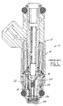
- FIG. 1 there is illustrated a prior art fuel injector, generally designated 10, including a housing assembly 12 mounting a coil assembly 14 and an armature 16 coupled to a needle valve 18.
- a housing 22 Surrounding the needle valve 18 is a housing 22 defining a fuel volume 24 in communication with a fuel flow passage 20 through the armature 16.
- a valve seat 26 At the lower end of housing 22 is a valve seat 26 defining an orifice 28 through which fuel is ejected from the fuel ejector into the engine.
- the coil 14 and armature 16 cooperate to open and close orifice 28 by periodic axial movement of needle valve 18 within fuel volume 24.
- FIG 2 there is illustrated the lower end of a fuel injector constructed in accordance with the present invention and which injector includes all of the elements of the fuel injector described in Figure 1. Additionally, however, provision is made for the creation of air bubbles in the fuel within the fuel volume 24 to provide a two-phase air bubble/fuel dispersion in the fuel volume for flow through the injector orifice.
- an air inlet 30 is provided through the side walls of the valve housing 22 defining the fuel volume 24.
- the air inlet may comprise an annular chamber 31 about the injector defining an air manifold in communication with one or more openings 36 to which air supply lines may be coupled and one or more ports 32 in direct communication with the fuel volume 24.
- Air filters 35 may be provided as necessary or desirable.
- Each port 32 is provided with a porous member 38 which is permeable to air and impermeable to fuel. Air is provided under pressure from a suitable air pressure source for flow through the porous member 38 into the fuel volume 24.
- a suitable air pressure source is disclosed in commonly owned co-pending U.S. application Serial No. 08/686,937 (Attorney Docket Nos. 94E7761 and 242-51), filed July 26, 1996, As illustrated, it is desirable to locate the air inlet 30 having the porous member 38 as close to the orifice 28 of the injector 10 as possible given size constraints and the need to seal the injector, for example, in the engine intake.
- each porous member 38 is such as to provide sufficiently small air bubbles in the fuel in the fuel volume so that the bubbles will not rise in the fuel or will rise only very slowly and at a rate which will not affect or substantially affect the mass flow of the two-phase air bubble/fuel dispersion through the injector orifice 28. It has been found that a pore size of 40 microns or less provides sufficiently small bubbles as to consistently enable a controlled mass of the air bubble/fuel dispersion through the injector orifice upon opening the needle valve.
- the porous members 38 may be formed of ceramic, metallic or foamed plastic materials or other materials which will provide a desired bubble size and substantially uniform distribution of bubbles into the fuel volume within the injector.
- the mass flow of bubbles can be changed by changing the pressure differential across the porous membrane, the area of the porous membrane, or the thickness of the membrane, or any two or more of these parameters, whereby the desired two-phase flow condition downstream of the orifice can be provided.
- the appropriate bubble size i.e., 40 microns or less, effervescence of the gas within the fuel is substantially precluded.
Landscapes
- Engineering & Computer Science (AREA)
- Chemical & Material Sciences (AREA)
- Combustion & Propulsion (AREA)
- Mechanical Engineering (AREA)
- General Engineering & Computer Science (AREA)
- Physics & Mathematics (AREA)
- Electromagnetism (AREA)
- Fuel-Injection Apparatus (AREA)
Description
- The present invention relates generally to fuel injectors, typically employed to inject fuel into an engine, and particularly relates to the formation of an air bubble/fuel dispersion in the fuel prior to spraying the fuel through the fuel injector orifice and to methods of operating the fuel injector.
- Fuel injector typically comprise an electromagnetically actuated needle valve disposed in a fuel volume and which needle valve is reciprocated axially within the fuel volume in response to energization and deenergization of an actuator to selectively open and close a flow path through the fuel injector. Particularly, the valve body or housing defining the fuel volume has an aperture or orifice at one end forming a seat for the end of the needle valve whereby its reciprocating motion enables an intermittent flow of fuel through the orifice. Typically, the fuel emitted from a fuel injector is atomized downstream of the orifice to provide the necessary fuel/air mixture in the combustion chamber of the engine.
- GB-A-2 023 226 discloses a fuel injector into which air is injected and mixed with fuel so that a mixture is formed wherein the air is present as bubbles. A porous insert is arranged in the mixing chamber to extend along the length thereof and forms a porous filter into which fuel flows and through which air diffuses to mix with the fuel.
- According to one aspect of the present invention, there is provided a fuel injector for injecting fuel into a combustion chamber of an engine the injector comprising:- a valve housing;an orifice formed in the valve housing; a valve assembly mounted within the valve housing for opening and closing the orifice; a fuel volume defined by the valve housing, the fuel volume being in communication with a fuel flow passage; a port formed in the valve housing for introducing air into the fuel volume; and a porous member located in the port for admitting air therethrough into said volume to establish a two-phase air bubble/fuel dispersion enabling two-phase flow of air bubbles and fuel from said volume through said orifice when the orifice is open; characterised in that the porous member is impermeable to fuel and has a pore size which is less than or equal to 40 microns.
- According to another aspect of the present invention, there is provided a method of operating a fuel injector as described above, characterised in that the method comprises forming an air bubble/fuel dispersion in the fuel volume by flowing air through the porous member into the fuel volume and flowing the air bubble/fuel dispersion through the orifice when the valve assembly opens the orifice.
- In accordance with the present invention, improved atomization, fuel economy and burn with resulting lower emissions are achieved by providing a two-phase air bubble/fuel dispersion in the fuel volume of the fuel injector upstream of the injector orifice enabling a controlled atomized flow of air and fuel through the injector orifice. It will be appreciated that, for most engines, it is highly desirable to provide a known controllable mass of fuel to the engine and that fuel atomization occurs downstream of the injector orifice. Because air bubbles have a propensity to rise in fuel, any effort to atomize the fuel upstream of the injector orifice would render substantially indeterminate the mass flow of fuel through the injector orifice. In accordance with the present invention and recognizing that bubble rise time is proportional to bubble size, the bubble size is maintained sufficiently small so that bubbles do not rise or rise very slowly such that a controllable mass of the air bubble/fuel dispersion can be ejected through the orifice of the injector. Thus, the present invention provides a homogeneous dispersion of very small air bubbles in the fuel such that the fuel/air ratio and hence the mass of the fuel supplied through the injector orifice remains a known substantially constant value.
- More particularly and according to the present invention, one or more porous members, i.e., a ceramic, metallic or foam plastic membrane, are provided, each having a pore size permeable to air and impermeable to fuel. Each porous member is preferably carried in an air inlet to the injector housing for flowing air directly into the fuel volume upstream of the injector orifice. By selecting a predetermined pore size, the size of the air bubbles formed in the fuel in the fuel volume by passing air through the member is controlled such that the bubbles do not substantially rise in the fuel or rise slowly whereby a substantially constant mass of two-phase air bubble/fuel dispersion is supplied to the engine through the orifice. It has been found that pore sizes of 40 microns or less provide an appropriately sized bubble of similar size in the fuel volume. The magnitude of the distribution of air bubbles in the fuel volume can be selected depending upon the difference in pressure across the porous membrane, the area of the porous membrane and/or the thickness of the membrane. Each of these three parameters may be adjusted to provide the desired bubble size distribution and mass of bubbles in the fuel, enabling creation of a desirable two-phase flow from the fuel volume to the injector through the orifice into the engine. The above-noted beneficial results of the present invention are achieved preferably upon engine start-up.
- Accordingly, it is a primary object of the present invention to provide a novel and improved fuel injector and methods of operating a fuel injector in which a two-phase air bubble/fuel dispersion is ejected through the injector orifice into the engine for improved atomization, fuel economy and burn with consequent decreased emissions.
-
- FIGURE 1 is a longitudinal cross-sectional view of a fuel injector according to the prior art; and
- FIGURE 2 is an enlarged cross-sectional view of the lower end of an injector constructed in accordance with the present invention.
-
- Referring now to Figure 1, there is illustrated a prior art fuel injector, generally designated 10, including a
housing assembly 12 mounting acoil assembly 14 and anarmature 16 coupled to aneedle valve 18. Surrounding theneedle valve 18 is ahousing 22 defining afuel volume 24 in communication with afuel flow passage 20 through thearmature 16. At the lower end ofhousing 22 is avalve seat 26 defining anorifice 28 through which fuel is ejected from the fuel ejector into the engine. It will be appreciated that thecoil 14 andarmature 16 cooperate to open andclose orifice 28 by periodic axial movement ofneedle valve 18 withinfuel volume 24. - Referring now to Figure 2, there is illustrated the lower end of a fuel injector constructed in accordance with the present invention and which injector includes all of the elements of the fuel injector described in Figure 1. Additionally, however, provision is made for the creation of air bubbles in the fuel within the
fuel volume 24 to provide a two-phase air bubble/fuel dispersion in the fuel volume for flow through the injector orifice. To accomplish this, anair inlet 30 is provided through the side walls of thevalve housing 22 defining thefuel volume 24. The air inlet may comprise anannular chamber 31 about the injector defining an air manifold in communication with one ormore openings 36 to which air supply lines may be coupled and one ormore ports 32 in direct communication with thefuel volume 24.Air filters 35 may be provided as necessary or desirable. Eachport 32 is provided with aporous member 38 which is permeable to air and impermeable to fuel. Air is provided under pressure from a suitable air pressure source for flow through theporous member 38 into thefuel volume 24. An example of one such air pressure source is disclosed in commonly owned co-pending U.S. application Serial No. 08/686,937 (Attorney Docket Nos. 94E7761 and 242-51), filed July 26, 1996, As illustrated, it is desirable to locate theair inlet 30 having theporous member 38 as close to theorifice 28 of theinjector 10 as possible given size constraints and the need to seal the injector, for example, in the engine intake. - The pore size of each
porous member 38 is such as to provide sufficiently small air bubbles in the fuel in the fuel volume so that the bubbles will not rise in the fuel or will rise only very slowly and at a rate which will not affect or substantially affect the mass flow of the two-phase air bubble/fuel dispersion through theinjector orifice 28. It has been found that a pore size of 40 microns or less provides sufficiently small bubbles as to consistently enable a controlled mass of the air bubble/fuel dispersion through the injector orifice upon opening the needle valve. Theporous members 38 may be formed of ceramic, metallic or foamed plastic materials or other materials which will provide a desired bubble size and substantially uniform distribution of bubbles into the fuel volume within the injector. To obtain the appropriate mass of bubbles in the fuel injector after selection of the proper pore size, the mass flow of bubbles can be changed by changing the pressure differential across the porous membrane, the area of the porous membrane, or the thickness of the membrane, or any two or more of these parameters, whereby the desired two-phase flow condition downstream of the orifice can be provided. With the appropriate bubble size, i.e., 40 microns or less, effervescence of the gas within the fuel is substantially precluded.
Claims (11)
- A fuel injector for injecting fuel into a combustion chamber of an engine the injector comprising:-characterised in that the porous member (38) is impermeable to fuel and has a pore size which is less than or equal to 40 microns.a valve housing (22);an orifice (28) formed in the valve housing (22);a valve assembly (14, 16, 18) mounted within the valve housing (22) for opening and closing the orifice (28);a fuel volume (24) defined by the valve housing (22), the fuel volume being in communication with a fuel flow passage (20);a port (32) formed in the valve housing (22) for introducing air into the fuel volume (24); anda porous member (38) located in the port for admitting air therethrough into said volume to establish a two-phase air bubble/fuel dispersion enabling two-phase flow of air bubbles and fuel from said volume through said orifice when the orifice is open (32);
- A fuel injector according to claim 1, wherein the porous member (38) is formed of a ceramic material.
- A fuel injector according to claim 1, wherein the porous member (38) is formed of a metallic material.
- A fuel injector according to claim 1, wherein the porous member (38) is formed of a foamed plastic material.
- A fuel injector according to any one of the preceding claims, wherein the valve housing (22) has a plurality of ports (32) each having a porous member (38) located therein.
- A method of operating a fuel injector according to any one of the preceding claims, characterised in that the method comprises forming an air bubble/fuel dispersion in the fuel volume (24) by flowing air through the porous member (38) into the fuel volume (24) and flowing the air bubble/fuel dispersion through the orifice (28) when the valve assembly (14, 16, 28) opens the orifice (28).
- A method according to claim 6, further comprising the step of controlling the mass of bubbles in the air bubble/fuel dispersion.
- A method according to claim 7, wherein the step of controlling the mass of bubbles in the air bubble/fuel dispersion comprises changing the pressure differential across the porous member (38).
- A method according to claim 7 or 8, wherein the step of controlling the mass of bubbles in the air bubble/fuel dispersion comprises changing the area of the porous member (38).
- A method according to any one of claims 7 to 9, wherein the step of controlling the mass of bubbles in the air bubble/fuel dispersion comprises changing the thickness of the porous member (38).
- A method according to any one of claims 6 to 10, further comprising the step of providing an air bubble size in which the air bubbles substantially do not rise in the air bubble/fuel dispersion.
Applications Claiming Priority (2)
| Application Number | Priority Date | Filing Date | Title |
|---|---|---|---|
| US686939 | 1996-07-26 | ||
| US08/686,939 US5730367A (en) | 1996-07-26 | 1996-07-26 | Fuel injector with air bubble/fuel dispersion prior to injection and methods of operation |
Publications (3)
| Publication Number | Publication Date |
|---|---|
| EP0821159A2 EP0821159A2 (en) | 1998-01-28 |
| EP0821159A3 EP0821159A3 (en) | 1998-02-04 |
| EP0821159B1 true EP0821159B1 (en) | 2003-01-22 |
Family
ID=24758368
Family Applications (1)
| Application Number | Title | Priority Date | Filing Date |
|---|---|---|---|
| EP97112220A Expired - Lifetime EP0821159B1 (en) | 1996-07-26 | 1997-07-17 | Fuel injector with air bubble/fuel dispersion prior to injection and method of operation |
Country Status (3)
| Country | Link |
|---|---|
| US (1) | US5730367A (en) |
| EP (1) | EP0821159B1 (en) |
| DE (1) | DE69718570T2 (en) |
Families Citing this family (24)
| Publication number | Priority date | Publication date | Assignee | Title |
|---|---|---|---|---|
| US6179227B1 (en) * | 1997-02-06 | 2001-01-30 | Siemens Automotive Corporation | Pressure swirl generator for a fuel injector |
| DE19736682A1 (en) * | 1997-08-22 | 1999-02-25 | Bosch Gmbh Robert | Fuel injector for internal combustion engine |
| US5996912A (en) * | 1997-12-23 | 1999-12-07 | Siemens Automotive Corporation | Flat needle for pressurized swirl fuel injector |
| US6328231B1 (en) | 1998-05-27 | 2001-12-11 | Siemens Automotive Corporation | Compressed natural gas injector having improved low noise valve needle |
| US6508418B1 (en) | 1998-05-27 | 2003-01-21 | Siemens Automotive Corporation | Contaminant tolerant compressed natural gas injector and method of directing gaseous fuel therethrough |
| US6431474B2 (en) | 1999-05-26 | 2002-08-13 | Siemens Automotive Corporation | Compressed natural gas fuel injector having magnetic pole face flux director |
| US6334580B2 (en) * | 1999-05-26 | 2002-01-01 | Siemens Automotive Corporation | Gaseous injector with columnated jet oriface flow directing device |
| US6405947B2 (en) | 1999-08-10 | 2002-06-18 | Siemens Automotive Corporation | Gaseous fuel injector having low restriction seat for valve needle |
| US6422488B1 (en) | 1999-08-10 | 2002-07-23 | Siemens Automotive Corporation | Compressed natural gas injector having gaseous dampening for armature needle assembly during closing |
| US6484700B1 (en) | 2000-08-24 | 2002-11-26 | Synerject, Llc | Air assist fuel injectors |
| US6402057B1 (en) | 2000-08-24 | 2002-06-11 | Synerject, Llc | Air assist fuel injectors and method of assembling air assist fuel injectors |
| US6302337B1 (en) | 2000-08-24 | 2001-10-16 | Synerject, Llc | Sealing arrangement for air assist fuel injectors |
| US6604695B1 (en) | 2000-09-25 | 2003-08-12 | Siemens Automotive Corporation | Method and fuel injector for setting gaseous injector static flow rate with injector stroke |
| US7104477B2 (en) | 2001-09-13 | 2006-09-12 | Synerject, Llc | Air assist fuel injector guide assembly |
| DE10314454B4 (en) * | 2003-03-30 | 2009-04-09 | Robert Bosch Gmbh | Vacuum flushing of an injector for internal combustion engines |
| WO2005016550A1 (en) | 2003-08-13 | 2005-02-24 | Unilever Plc | Domestic spray device |
| WO2005016548A1 (en) * | 2003-08-13 | 2005-02-24 | Unilever Plc | Nozzle for a spray device |
| FR2899279A1 (en) * | 2006-03-30 | 2007-10-05 | Peugeot Citroen Automobiles Sa | Limiting the fouling of fuel injector nozzles in internal combustion engine, comprises generating inert gas microbubbles in the fuel and diminishing the bond strength of injector walls and molecules of depositable compounds |
| US20080191633A1 (en) * | 2007-02-12 | 2008-08-14 | Chi-Shih Lai | Serial light-emitting light structure |
| FR2929999B1 (en) * | 2008-04-10 | 2012-09-28 | Peugeot Citroen Automobiles Sa | ADDITIVE FUEL SUPPLY OF A COMBUSTION ENGINE |
| US9291139B2 (en) * | 2008-08-27 | 2016-03-22 | Woodward, Inc. | Dual action fuel injection nozzle |
| JP5115654B2 (en) * | 2010-07-01 | 2013-01-09 | トヨタ自動車株式会社 | Fuel injection valve and internal combustion engine |
| CN111189045B (en) * | 2020-01-17 | 2021-12-14 | 哈尔滨工业大学 | A kind of fuel-stabilized ultra-fine atomizing nozzle and atomizing method |
| US20240295205A1 (en) * | 2023-03-02 | 2024-09-05 | Caterpillar Inc. | Fuel system having fuel injector boot assembly with integrated filter |
Family Cites Families (22)
| Publication number | Priority date | Publication date | Assignee | Title |
|---|---|---|---|---|
| US4088104A (en) * | 1975-07-10 | 1978-05-09 | Ibbott Jack Kenneth | Device and method for improving vaporization rate of volatile fuels |
| US4020803A (en) * | 1975-10-30 | 1977-05-03 | The Bendix Corporation | Combined fuel injection and intake valve for electronic fuel injection engine systems |
| US4157084A (en) * | 1977-09-20 | 1979-06-05 | Wallis Marvin E | Fuel injection system and method for internal combustion engine |
| US4137875A (en) * | 1977-12-12 | 1979-02-06 | Medina Sergio P | Auxiliary air inlet device for internal combustion engines |
| DE2826025A1 (en) * | 1978-06-14 | 1979-12-20 | Daimler Benz Ag | MULTICYLINDRICAL COMBUSTION ENGINE |
| JPS6056908B2 (en) * | 1978-11-06 | 1985-12-12 | 株式会社日立製作所 | Fuel control device for fuel injection system |
| US4359035A (en) * | 1978-12-29 | 1982-11-16 | Johnson Edward E | Intake manifold fuel atomizing screen |
| JPS59131575U (en) * | 1983-02-23 | 1984-09-04 | トヨタ自動車株式会社 | Fuel injection valve for electronically controlled engines |
| US4628890A (en) * | 1984-08-31 | 1986-12-16 | Freeman Winifer W | Fuel atomizer |
| US4794901A (en) * | 1987-06-16 | 1989-01-03 | Industrial Technology Research Institute | Low pressure air assisted fuel injection apparatus for engine |
| US4846402A (en) * | 1988-02-03 | 1989-07-11 | Wheelabrator Air Pollution Control, Inc. | Spray nozzle and method of preventing solids build-up thereon |
| DE4007788A1 (en) * | 1990-03-12 | 1991-09-19 | Bosch Gmbh Robert | DEVICE FOR INJECTING A FUEL-GAS MIXTURE |
| US5269283A (en) * | 1990-09-14 | 1993-12-14 | Thompson Technologies, Inc. | Emission control device for fuel injection and carbureted engines |
| DE4112150C2 (en) * | 1990-09-21 | 1998-11-19 | Bosch Gmbh Robert | Perforated body and valve with perforated body |
| DE4121372A1 (en) * | 1991-05-31 | 1992-12-03 | Bosch Gmbh Robert | DEVICE FOR INJECTING A FUEL-GAS MIXTURE |
| DE4129834A1 (en) * | 1991-09-07 | 1993-03-11 | Bosch Gmbh Robert | DEVICE FOR INJECTING A FUEL-GAS MIXTURE |
| JP3053934B2 (en) * | 1991-10-31 | 2000-06-19 | 愛三工業株式会社 | Multi-hole injector |
| US5170766A (en) * | 1992-01-16 | 1992-12-15 | Orbital Walbro Corporation | Fuel and air injection for multi-cylinder internal combustion engines |
| US5323753A (en) * | 1992-10-19 | 1994-06-28 | Ford Motor Company | Induction system for an internal combustion engine |
| GB2273130B (en) * | 1992-12-07 | 1995-12-13 | Nippon Denso Co | Fuel injection system for multi-cylinder internal combustion engine |
| JPH07259701A (en) * | 1994-03-25 | 1995-10-09 | Keihin Seiki Mfg Co Ltd | Electromagnetic fuel injection valve |
| DE4444417B4 (en) * | 1994-12-14 | 2005-01-05 | Robert Bosch Gmbh | Fuel supply system |
-
1996
- 1996-07-26 US US08/686,939 patent/US5730367A/en not_active Expired - Fee Related
-
1997
- 1997-07-17 EP EP97112220A patent/EP0821159B1/en not_active Expired - Lifetime
- 1997-07-17 DE DE69718570T patent/DE69718570T2/en not_active Expired - Fee Related
Also Published As
| Publication number | Publication date |
|---|---|
| US5730367A (en) | 1998-03-24 |
| EP0821159A3 (en) | 1998-02-04 |
| DE69718570T2 (en) | 2003-09-25 |
| DE69718570D1 (en) | 2003-02-27 |
| EP0821159A2 (en) | 1998-01-28 |
Similar Documents
| Publication | Publication Date | Title |
|---|---|---|
| US5730367A (en) | Fuel injector with air bubble/fuel dispersion prior to injection and methods of operation | |
| US5884611A (en) | Effervescent injector for diesel engines | |
| US4429674A (en) | Multicylinder internal combustion engine | |
| US5323966A (en) | Apparatus for injecting a fuel-air mixture | |
| US5996912A (en) | Flat needle for pressurized swirl fuel injector | |
| CN86107587A (en) | About the quantitative improvement of fuel oil | |
| US5109824A (en) | Electromagnetic fuel injection valve | |
| JPS6056908B2 (en) | Fuel control device for fuel injection system | |
| US4280661A (en) | Intermittent injection type fuel injection valve | |
| JPH05126011A (en) | Multiple hole type injector | |
| EP1020639B1 (en) | Pulsed air assist fuel injector | |
| US7303144B2 (en) | Reduction in hydrocarbon emission via spray pattern control through fuel pressure control in fuel injection systems | |
| US5904299A (en) | Fuel injector | |
| JP2004514835A (en) | Fuel injection valve | |
| US4317542A (en) | Fuel injector | |
| KR20010034747A (en) | Fuel injector with porous element for atomizing fuel under air pressure | |
| EP0821158B1 (en) | Fuel/air supply system for a fuel injector and methods of operation | |
| JP2002221128A (en) | Injection valve | |
| JP2005282420A (en) | Fuel injection valve | |
| US7472894B2 (en) | Engine carburetion | |
| JP2005098231A (en) | Fuel injection valve | |
| JP2668130B2 (en) | Fuel injection device for internal combustion engine | |
| JPS6196173A (en) | Fuel injection valve | |
| JPH02252967A (en) | Fuel injector for internal combustion engine | |
| JPH0893593A (en) | Electromagnetic fuel injection valve |
Legal Events
| Date | Code | Title | Description |
|---|---|---|---|
| PUAI | Public reference made under article 153(3) epc to a published international application that has entered the european phase |
Free format text: ORIGINAL CODE: 0009012 |
|
| PUAL | Search report despatched |
Free format text: ORIGINAL CODE: 0009013 |
|
| AK | Designated contracting states |
Kind code of ref document: A2 Designated state(s): DE FR GB IT |
|
| AK | Designated contracting states |
Kind code of ref document: A3 Designated state(s): AT BE CH DE DK ES FI FR GB GR IE IT LI LU MC NL PT SE |
|
| 17P | Request for examination filed |
Effective date: 19980514 |
|
| AKX | Designation fees paid |
Free format text: DE FR GB IT |
|
| RBV | Designated contracting states (corrected) |
Designated state(s): DE FR GB IT |
|
| 17Q | First examination report despatched |
Effective date: 20000203 |
|
| GRAG | Despatch of communication of intention to grant |
Free format text: ORIGINAL CODE: EPIDOS AGRA |
|
| GRAG | Despatch of communication of intention to grant |
Free format text: ORIGINAL CODE: EPIDOS AGRA |
|
| GRAH | Despatch of communication of intention to grant a patent |
Free format text: ORIGINAL CODE: EPIDOS IGRA |
|
| RAP1 | Party data changed (applicant data changed or rights of an application transferred) |
Owner name: SIEMENS VDO AUTOMOTIVE CORPORATION |
|
| GRAH | Despatch of communication of intention to grant a patent |
Free format text: ORIGINAL CODE: EPIDOS IGRA |
|
| GRAA | (expected) grant |
Free format text: ORIGINAL CODE: 0009210 |
|
| AK | Designated contracting states |
Kind code of ref document: B1 Designated state(s): DE FR GB IT |
|
| REG | Reference to a national code |
Ref country code: GB Ref legal event code: FG4D |
|
| REF | Corresponds to: |
Ref document number: 69718570 Country of ref document: DE Date of ref document: 20030227 Kind code of ref document: P |
|
| PGFP | Annual fee paid to national office [announced via postgrant information from national office to epo] |
Ref country code: GB Payment date: 20030710 Year of fee payment: 7 |
|
| PGFP | Annual fee paid to national office [announced via postgrant information from national office to epo] |
Ref country code: FR Payment date: 20030725 Year of fee payment: 7 |
|
| PGFP | Annual fee paid to national office [announced via postgrant information from national office to epo] |
Ref country code: DE Payment date: 20030916 Year of fee payment: 7 |
|
| ET | Fr: translation filed | ||
| PLBE | No opposition filed within time limit |
Free format text: ORIGINAL CODE: 0009261 |
|
| STAA | Information on the status of an ep patent application or granted ep patent |
Free format text: STATUS: NO OPPOSITION FILED WITHIN TIME LIMIT |
|
| 26N | No opposition filed |
Effective date: 20031023 |
|
| PG25 | Lapsed in a contracting state [announced via postgrant information from national office to epo] |
Ref country code: GB Free format text: LAPSE BECAUSE OF NON-PAYMENT OF DUE FEES Effective date: 20040717 |
|
| PG25 | Lapsed in a contracting state [announced via postgrant information from national office to epo] |
Ref country code: DE Free format text: LAPSE BECAUSE OF NON-PAYMENT OF DUE FEES Effective date: 20050201 |
|
| GBPC | Gb: european patent ceased through non-payment of renewal fee |
Effective date: 20040717 |
|
| PG25 | Lapsed in a contracting state [announced via postgrant information from national office to epo] |
Ref country code: FR Free format text: LAPSE BECAUSE OF NON-PAYMENT OF DUE FEES Effective date: 20050331 |
|
| REG | Reference to a national code |
Ref country code: FR Ref legal event code: ST |
|
| PG25 | Lapsed in a contracting state [announced via postgrant information from national office to epo] |
Ref country code: IT Free format text: LAPSE BECAUSE OF NON-PAYMENT OF DUE FEES Effective date: 20050717 |