EP0821107B1 - System and procedure to transfer a load from a cargo barge to a substructure - Google Patents
System and procedure to transfer a load from a cargo barge to a substructure Download PDFInfo
- Publication number
- EP0821107B1 EP0821107B1 EP97202264A EP97202264A EP0821107B1 EP 0821107 B1 EP0821107 B1 EP 0821107B1 EP 97202264 A EP97202264 A EP 97202264A EP 97202264 A EP97202264 A EP 97202264A EP 0821107 B1 EP0821107 B1 EP 0821107B1
- Authority
- EP
- European Patent Office
- Prior art keywords
- substructure
- load
- legs
- barge
- cargo barge
- Prior art date
- Legal status (The legal status is an assumption and is not a legal conclusion. Google has not performed a legal analysis and makes no representation as to the accuracy of the status listed.)
- Expired - Lifetime
Links
- 238000000034 method Methods 0.000 title claims description 14
- 230000013011 mating Effects 0.000 claims description 17
- 238000010276 construction Methods 0.000 claims description 6
- 239000004576 sand Substances 0.000 claims description 6
- XLYOFNOQVPJJNP-UHFFFAOYSA-N water Substances O XLYOFNOQVPJJNP-UHFFFAOYSA-N 0.000 claims description 6
- 239000000463 material Substances 0.000 claims description 5
- 239000012858 resilient material Substances 0.000 claims description 2
- 238000013016 damping Methods 0.000 claims 1
- 210000003141 lower extremity Anatomy 0.000 claims 1
- 238000009434 installation Methods 0.000 description 5
- 230000004224 protection Effects 0.000 description 5
- 229910000831 Steel Inorganic materials 0.000 description 4
- 239000010959 steel Substances 0.000 description 4
- 239000006096 absorbing agent Substances 0.000 description 3
- 239000004677 Nylon Substances 0.000 description 2
- 238000005516 engineering process Methods 0.000 description 2
- 229920001778 nylon Polymers 0.000 description 2
- 230000008878 coupling Effects 0.000 description 1
- 238000010168 coupling process Methods 0.000 description 1
- 238000005859 coupling reaction Methods 0.000 description 1
- 230000007613 environmental effect Effects 0.000 description 1
- 238000012986 modification Methods 0.000 description 1
- 230000004048 modification Effects 0.000 description 1
Images









Classifications
-
- B—PERFORMING OPERATIONS; TRANSPORTING
- B63—SHIPS OR OTHER WATERBORNE VESSELS; RELATED EQUIPMENT
- B63B—SHIPS OR OTHER WATERBORNE VESSELS; EQUIPMENT FOR SHIPPING
- B63B27/00—Arrangement of ship-based loading or unloading equipment for cargo or passengers
- B63B27/30—Arrangement of ship-based loading or unloading equipment for transfer at sea between ships or between ships and off-shore structures
-
- B—PERFORMING OPERATIONS; TRANSPORTING
- B63—SHIPS OR OTHER WATERBORNE VESSELS; RELATED EQUIPMENT
- B63B—SHIPS OR OTHER WATERBORNE VESSELS; EQUIPMENT FOR SHIPPING
- B63B21/00—Tying-up; Shifting, towing, or pushing equipment; Anchoring
- B63B21/04—Fastening or guiding equipment for chains, ropes, hawsers, or the like
-
- E—FIXED CONSTRUCTIONS
- E02—HYDRAULIC ENGINEERING; FOUNDATIONS; SOIL SHIFTING
- E02B—HYDRAULIC ENGINEERING
- E02B17/00—Artificial islands mounted on piles or like supports, e.g. platforms on raisable legs or offshore constructions; Construction methods therefor
-
- E—FIXED CONSTRUCTIONS
- E02—HYDRAULIC ENGINEERING; FOUNDATIONS; SOIL SHIFTING
- E02B—HYDRAULIC ENGINEERING
- E02B17/00—Artificial islands mounted on piles or like supports, e.g. platforms on raisable legs or offshore constructions; Construction methods therefor
- E02B17/02—Artificial islands mounted on piles or like supports, e.g. platforms on raisable legs or offshore constructions; Construction methods therefor placed by lowering the supporting construction to the bottom, e.g. with subsequent fixing thereto
- E02B17/021—Artificial islands mounted on piles or like supports, e.g. platforms on raisable legs or offshore constructions; Construction methods therefor placed by lowering the supporting construction to the bottom, e.g. with subsequent fixing thereto with relative movement between supporting construction and platform
- E02B17/024—Artificial islands mounted on piles or like supports, e.g. platforms on raisable legs or offshore constructions; Construction methods therefor placed by lowering the supporting construction to the bottom, e.g. with subsequent fixing thereto with relative movement between supporting construction and platform shock absorbing means for the supporting construction
-
- E—FIXED CONSTRUCTIONS
- E02—HYDRAULIC ENGINEERING; FOUNDATIONS; SOIL SHIFTING
- E02B—HYDRAULIC ENGINEERING
- E02B3/00—Engineering works in connection with control or use of streams, rivers, coasts, or other marine sites; Sealings or joints for engineering works in general
- E02B3/20—Equipment for shipping on coasts, in harbours or on other fixed marine structures, e.g. bollards
- E02B3/24—Mooring posts
-
- E—FIXED CONSTRUCTIONS
- E02—HYDRAULIC ENGINEERING; FOUNDATIONS; SOIL SHIFTING
- E02B—HYDRAULIC ENGINEERING
- E02B17/00—Artificial islands mounted on piles or like supports, e.g. platforms on raisable legs or offshore constructions; Construction methods therefor
- E02B2017/0039—Methods for placing the offshore structure
-
- E—FIXED CONSTRUCTIONS
- E02—HYDRAULIC ENGINEERING; FOUNDATIONS; SOIL SHIFTING
- E02B—HYDRAULIC ENGINEERING
- E02B17/00—Artificial islands mounted on piles or like supports, e.g. platforms on raisable legs or offshore constructions; Construction methods therefor
- E02B2017/0039—Methods for placing the offshore structure
- E02B2017/0047—Methods for placing the offshore structure using a barge
Definitions
- the present invention relates to a system and procedure to transfer a load from a cargo barge to a substructure. More particularly, the present invention relates to a system and procedure to transfer, at sea, a load on the fixed legs emerging from water of a substructure, said load specially fabricated in the construction yard and transported to said substructure by means of a suitable cargo barge.
- This installation has requested the mooring of a suitable cargo barge, suitably prepared with an integrated module therein charged, inside the opening of a substructure fixed to the bottom sea, which emerged from the sea level with two towers having four legs each; the subsequent lowering of the cargo barge is made by ballast pumped inside the transport vessel, in order to transfer gradually the weight of the load from the cargo barge to the substructure.
- the Applicant has now found a simple system and method, fast and safe, which give the opportunity to transfer, at sea, a load from a cargo barge to a substructure which, unlike the aforementioned system, combine the active and passive action of the components of the present invention accelerating, in this way, the transferring time.
- the present invention therefore provides an apparatus as defined in claim 1.
- load any kind of structure, integrated module or deck, suitably built in a construction yard
- substructure any kind of structure, fixed or anchored to the sea bottom.
- cargo barge any kind of floatable means properly prepared to transport said load.
- Said cargo barge is equipped with an adequate ballasting system well known to those skilled in the art.
- the system (c) to protect, locally or totally, the cargo barge sides and the substructure legs, to damp the impact caused by the wave between the cargo barge and the substructure legs, is constituted by hard timber or any other material suitable to absorb any impact loads.
- the cargo barge arrest system (d) is composed by hard timber or any other material suitable to absorb any impact loads.
- the systems (c) and (d) permit, jointly, the automatic alignment of the load legs on the cargo barge with the substructure legs (mooring mating of the cargo barge).
- step B1 the hydraulic jacks (b' 3 ) stroke will be as much as to assure the partially transfer of the load to the substructure.
- Figure 1 shows a mooring waiting configuration of a cargo barge 1 with a load 2 set on the longitudinal axis of the cargo barge, moored in front of a substructure 3.
- the substructure 3 comprises a number of legs 3A to 3D.
- the mooring of the cargo barge 1 to the substructure 3 is carried out by a serial of mooring wires 8 and anchors 9, some nylon wires 8a connected to the substructure outer legs 3/A and two steel wires (with nylon stretcher) 8b connected to the substructure inner legs 3/D.
- the mooring steel wires 8 with their respective anchors 9, have been prepared in advance by the common offshore art and then connected to the mooring steel wires coming from the cargo barge.
- Items 4 and 6 are the leading tugs, which are employed during the whole operation and which are considered as backup to the mooring system.
- Items 5 and 7 are the steering tugs, which are used both as mooring wires 8 and anchor 9 handling and as backup to the mooring system.
- Item 10 is an hinged horizontal sheave that can be opened which will be analysed, in detail, later.
- the cargo barge 1 may be any floatable means and the load 2 may be set on the transversal axis, meanwhile the mooring system represented by the items 8, 8a, 8b and 9, and the distance of the cargo barge 1 from the substructure 3, may vary depending from the environmental conditions of the installation site.
- the mooring wire 8 which before was passing through the hinged horizontal sheave that can be opened 10, is now passing through a normal horizontal sheave, which is well known to those skilled in the art.
- FIGS 3/a, 3/b, 3/c and 3/d illustrate the hinged horizontal sheave that can be opened in which its hinged part 10 is supported by the fixed part 13. Said hinged sheave allows the mooring wire 8 to be shifted instantly from the middle-fore sides of the barge 1 to the middle-aft sides.
- the position of the hinged horizontal sheave that can be opened 10 may vary according to the necessity of the case.
- the mooring wire 8 is passed through the sheave 15 of the hinged part 10. All the assembly is welded out on a suitable grillage 16 fixed on the barge deck 1. Two lifting pins 18 are used to position the assembly.
- the hinged part 10 is fixed to the permanent part 13 by means of a removable pin 11 and two fixed pins 12.
- the removable pin 11 has a padeye 17 where a pulling steel wire, coming from a winch or a chain block or a tirfor or any other pulling means known to those skilled in the art, is connected.
- the hinged part 10 will raise automatically in order to make the mooring wire 8 passing to position 10/a (see Figure 2) through a conventional horizontal sheave.
- Item 14 is an impact absorber covered with hard timber, fixed on the cargo barge deck 1, in order to safeguard the integrity of the cargo barge deck 1 and of the hinged part 10.
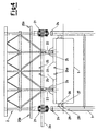
- FIG. 4 it illustrates a load 2 on a cargo barge 1 inside a slot of a substructure 3 fixed or anchored to the sea bottom, in which it are underlined the main components of the present invention: item 21 is the main transfer system (ALS) fixed amidst of the cellar deck main frame 2a (solution A); item 22 is the secondary transfer system; item 23 is the grillage for the seafastening on the cargo barge 1; item 24 is the support plate inside the substructure legs 3 fixed at a predermined height; item 25 is the hydraulic power pack for the ALS jacks, as item 25a is the hydraulic power pack for the BRS jack; item 25b is the accumulator for the ALS; items 26 and 27 are the local fendering system on the cargo barge sides meanwhile, items 28 and 29, are the fendering system on inner and outer substructure legs.
- ALS main transfer system
- Figure 4/a illustrates the structural solution of the ALS 21 fixed underneath the cellar deck main frame 2a (solution B).
- Figure 5 depicts the typical retracted 4000 tons configuration of the ALS 21, where 2 and 3 are, respectively, the load and substructure legs, 30 is the actuated leg slided inside the load leg, 31 is the special joint which is part of the load leg 2, where the upper part 33 of the hydraulic jack 21a is connected to the padear 37 by means of the pin 34.
- Item 32 is the second special joint which is integral part of the actuated leg 30, where the inner part 42 of the hydraulic jack 21b (see Figure 5a) is connected to the padear 43 by means of the pin 40.
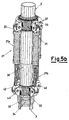
- Figures 5/a and 5/b depict the typical extended 4000 and 2000 tons configuration, respectively, of the ALS 21 in which the maximum stroke is indicated by the detail 21b.
- Item 24 is the support plate fixed inside the substructure leg 3 at a predetermined height which receives, partially, the weight transferred by the actuated leg 30.
- Figures 5/c, 5/d and 5/e illustrate the various arrangement of the ALS 21 which can be fixed, respectively, amidst, underneath and on cellar deck main frame 2a.
- item 2 is the load leg with a special joint 31, shaped with a serial of padear 37 into which is fixed the attachment part 33, with pin 34 and washer 35 of the upper part of the hydraulic jack 21/a.
- item 30 is the actuated leg which slides inside the load leg 2 with a second special joint 32, shaped with a serial of padear 43 into which is fixed the attachment part 42, with pin 40 and washer 41 of the inner part of the hydraulic jack 21/b.
- Item 3 is the substructure leg. No mention is made to the ALS jacks power pack 25 (see Figures 4 and 4/a) and to the BRS jacks power pack 25/a (see Figures 4 and 4/a), as well as to the hydraulic jacks 25/b accelerator (see Figures 4 and 4/a), because it will be apparent to those skilled in the art that power packs and accelerators are components well known in the art.
- Item 51 is a rubber, or any other resilient material known to those skilled in the art, impact absorber.
- the fenders assembly 54 and 58 are on two different elevations to optimise the tendering system, which with their hard timber 55 and 59 will absorb any impact between cargo barge sides and substructure legs 3/A and 3/D in the mating configuration, reducing and/or eliminating any side motion, in combination with the substructure legs assembly 56 and 60 with their hard timber protection 57 and 61.
- the fender protections 54, 58, 56 and 60 may vary according to the necessity of the case and the shape of the stoppers 62 and 63 may vary on other suitable arrangements providing the automatic mating configuration meanwhile, the hard timber protections 55, 57, 59, 61, 62 and 63, may be composed by other reliable materials well known to the skilled in the art.
Landscapes
- Engineering & Computer Science (AREA)
- General Engineering & Computer Science (AREA)
- Mechanical Engineering (AREA)
- Ocean & Marine Engineering (AREA)
- Civil Engineering (AREA)
- Structural Engineering (AREA)
- Combustion & Propulsion (AREA)
- Chemical & Material Sciences (AREA)
- Environmental & Geological Engineering (AREA)
- Ship Loading And Unloading (AREA)
- Tents Or Canopies (AREA)
- Control Of Vending Devices And Auxiliary Devices For Vending Devices (AREA)
- Financial Or Insurance-Related Operations Such As Payment And Settlement (AREA)
- Management, Administration, Business Operations System, And Electronic Commerce (AREA)
Description
- The present invention relates to a system and procedure to transfer a load from a cargo barge to a substructure. More particularly, the present invention relates to a system and procedure to transfer, at sea, a load on the fixed legs emerging from water of a substructure, said load specially fabricated in the construction yard and transported to said substructure by means of a suitable cargo barge.
- In the state of the art other systems are already known to transfer at sea loads from cargo barges to the platforms substructure. Said transfer has been performed, until now, by lifting the load to be transferred by means of middle/big pontoons or crane vessels, subdividing said loads in multiple modules depending on the weight of the load to be lifted. This well known method, has however always obliged to maintain the loads to be transferred within preestablished limits due to many problems among which, first of all, the availability of middle/big pontoons or crane vessels associated with their cost indeed very expensive.
- The document from White et al. "Offshore Installation of an Integrated Deck onto a Preinstalled Jacket" from the Offshore Technology Conference, Houston, 1986, vol.8, pages 321-330, constitutes the most pertinent prior art reference and discloses a technique of assembling a deck in an offshore platform. Such technique provides to join the deck legs and the jacket legs by stab pins lowered by hydraulic cylinders standing in the inner part of deck legs. Said stab pins are received and centred by catching cones of the jacket legs, so obtaining a resilient coupling the deck legs and jacket legs. During its assembling with the. jacket, the deck is supported by the servicing barge through a drop block assembly, an instantaneous collapsible support, that allows a fast disengagement of the barge.
- Many other methods have been known in the art. One of the most recent, is that one reported, for example, by W.D. Martell and S.M. Beattie of Enercon Eng. Inc. on: "Integrated float-over deck design considerations", work presented at the Offshore Technology Conference, O.T.C. 8119, held in Houston, Texas, from 6 to 9 May 1996, where the authors have detailed the installation of two large modules by means of the transfer from a cargo barge to a substructure in South China sea (M-Field) for Shell Sarawak.
- This installation has requested the mooring of a suitable cargo barge, suitably prepared with an integrated module therein charged, inside the opening of a substructure fixed to the bottom sea, which emerged from the sea level with two towers having four legs each; the subsequent lowering of the cargo barge is made by ballast pumped inside the transport vessel, in order to transfer gradually the weight of the load from the cargo barge to the substructure.
- This experience has shown, even to the participants to the installation, the real possibility to transfer big loads at sea world wide, assuming that the significant wave height and the relevant impact value between cargo barge side and substructure legs, remain within preestablished and acceptable values.
- The Applicant has now found a simple system and method, fast and safe, which give the opportunity to transfer, at sea, a load from a cargo barge to a substructure which, unlike the aforementioned system, combine the active and passive action of the components of the present invention accelerating, in this way, the transferring time.
- The present invention therefore provides an apparatus as defined in
claim 1. - In the present invention is called load any kind of structure, integrated module or deck, suitably built in a construction yard, meanwhile is called substructure any kind of structure, fixed or anchored to the sea bottom.
- In the present invention with the word cargo barge is indicated any kind of floatable means properly prepared to transport said load. Said cargo barge is equipped with an adequate ballasting system well known to those skilled in the art.
- The system (c) to protect, locally or totally, the cargo barge sides and the substructure legs, to damp the impact caused by the wave between the cargo barge and the substructure legs, is constituted by hard timber or any other material suitable to absorb any impact loads.
- The cargo barge arrest system (d) is composed by hard timber or any other material suitable to absorb any impact loads. The systems (c) and (d) permit, jointly, the automatic alignment of the load legs on the cargo barge with the substructure legs (mooring mating of the cargo barge).
- Falls within the aim of the present invention a method based on the afore mentioned apparatus to transfer, at sea, a load on the fixed legs emerging from water of a substructure, said load specially fabricated in the construction yard and transported to said substructure by means of a suitable cargo barge, as defined in
claim 5. - At the end of the step B4 of the procedure disclosed above, once that the cargo barge is out of substructure slot, said cargo barge is unmoored and returned to the shore-yard meanwhile the mooring system is recovered.
- Through the step B1, the hydraulic jacks (b'3) stroke will be as much as to assure the partially transfer of the load to the substructure.
- The advantages of the present invention will be better understood by referring to the following detailed description of the attached drawings in which the Figures from 1 to 12 represent:
- Figure 1: is the cargo barge mooring waiting configuration;
- Figure 2: is the cargo barge mooring mating configuration;
- Figure 3: is the horizontal sheave that can be opened;
- Figure 3/a: is a side elevation view of the horizontal sheave that can be opened;
- Figure 3/b: is a left side elevation view of the horizontal sheave that can be opened;
- Figure 3/c: is a right side elevation view of the horizontal sheave that can be opened;
- Figure 3/d: is a top plan view of the horizontal sheave that can be opened;
- Figure 4: is the elevation view, Solution A, showing the substructure/load in the mating configuration;
- Figure 4/a: is the elevation view, Solution B, showing the substructure/load in the mating configuration;
- Figure 5: is the activated leg in the 4000 tons typical retracted configuration (ALS);
- Figure 5/a: is the activated leg in the 4000 tons typical extended configuration (ALS);
- Figure 5/b: is the activated leg in the 2000 tons typical extended configuration (ALS);
- Figure 5/c: is the activated leg, solution A (ALS);
- Figure 5/d: is the activated leg, solution B (ALS);
- Figure 5/e: is the activated leg, solution C (ALS);
- Figure 6: is the activated leg detailed (ALS);
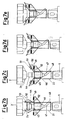
- Figures 7/b, 7/c, 7/d, 7/e: show a step by step cargo barge release system (BRS);
- Figure 7/a: is the detailed cargo barge release system (BRS) ;
- Figure 8: is the assembly of the cargo barge release system (BRS);
- Figure 8/a: is the detailed cargo barge release system (BRS);
- Figure 9: is the cargo barge release system (BRS) in the closed transport position;
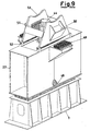
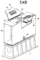
- Figure 10: is the cargo barge release system (BRS) in the open mating position;
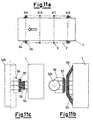
- Figure 11/a: is a general view of the mating alignment side fender;
- Figures 11/b, 11/c: are enlarged views of the details of the mating alignment side fender;
- Figure 12/a: is a general view of the mating alignment fender and stopper;
- Figures 12/b, 12/c: are enlarged views of the details of the mating alignment fender and stopper.
-
- The Figures 1-12 are referred to a preferred embodiment of the present invention: therefore it has to be intended that the invention is not limited by said Figures 1-12.
- Referring now to the drawings exhaustively, Figure 1 shows a mooring waiting configuration of a
cargo barge 1 with aload 2 set on the longitudinal axis of the cargo barge, moored in front of asubstructure 3. Thesubstructure 3 comprises a number of legs 3A to 3D. The mooring of thecargo barge 1 to thesubstructure 3 is carried out by a serial ofmooring wires 8 andanchors 9, somenylon wires 8a connected to the substructureouter legs 3/A and two steel wires (with nylon stretcher) 8b connected to the substructureinner legs 3/D. - The
mooring steel wires 8 with theirrespective anchors 9, have been prepared in advance by the common offshore art and then connected to the mooring steel wires coming from the cargo barge. - Items 4 and 6 are the leading tugs, which are employed during the whole operation and which are considered as backup to the mooring system.
-
Items mooring wires 8 andanchor 9 handling and as backup to the mooring system. -
Item 10 is an hinged horizontal sheave that can be opened which will be analysed, in detail, later. - Those skilled in the art will recognise that the
cargo barge 1 may be any floatable means and theload 2 may be set on the transversal axis, meanwhile the mooring system represented by theitems cargo barge 1 from thesubstructure 3, may vary depending from the environmental conditions of the installation site. - Analysing now Figure 2, where the mooring mating configuration is illustrated, the
cargo barge 1 has been manoeuvred inside the slot of thesubstructure 3, in order to have automatically the alignment between the legs of theload 2 andsubstructure 3. Said automatic alignment will be analysed, in detail, later. - The
mooring wire 8, which before was passing through the hinged horizontal sheave that can be opened 10, is now passing through a normal horizontal sheave, which is well known to those skilled in the art. - Figures 3/a, 3/b, 3/c and 3/d illustrate the hinged horizontal sheave that can be opened in which its hinged
part 10 is supported by the fixedpart 13. Said hinged sheave allows themooring wire 8 to be shifted instantly from the middle-fore sides of thebarge 1 to the middle-aft sides. - It will be apparent, to those skilled in the art, that the position of the hinged horizontal sheave that can be opened 10, may vary according to the necessity of the case. By way of common offshore art, the
mooring wire 8 is passed through thesheave 15 of the hingedpart 10. All the assembly is welded out on asuitable grillage 16 fixed on thebarge deck 1. Two liftingpins 18 are used to position the assembly. - The hinged
part 10 is fixed to thepermanent part 13 by means of aremovable pin 11 and two fixed pins 12. Theremovable pin 11 has apadeye 17 where a pulling steel wire, coming from a winch or a chain block or a tirfor or any other pulling means known to those skilled in the art, is connected. - When the
mooring wire 8 is close to the inner substructure legs, the pulling wire is actioned in order to disengage theremovable pin 11. - The hinged
part 10 will raise automatically in order to make themooring wire 8 passing to position 10/a (see Figure 2) through a conventional horizontal sheave. -
Item 14 is an impact absorber covered with hard timber, fixed on thecargo barge deck 1, in order to safeguard the integrity of thecargo barge deck 1 and of the hingedpart 10. - Referring now to Figure 4, it illustrates a
load 2 on acargo barge 1 inside a slot of asubstructure 3 fixed or anchored to the sea bottom, in which it are underlined the main components of the present invention:item 21 is the main transfer system (ALS) fixed amidst of the cellar deckmain frame 2a (solution A);item 22 is the secondary transfer system;item 23 is the grillage for the seafastening on thecargo barge 1;item 24 is the support plate inside thesubstructure legs 3 fixed at a predermined height;item 25 is the hydraulic power pack for the ALS jacks, asitem 25a is the hydraulic power pack for the BRS jack;item 25b is the accumulator for the ALS;items items - Figure 4/a illustrates the structural solution of the
ALS 21 fixed underneath the cellar deckmain frame 2a (solution B). - Figure 5 depicts the typical retracted 4000 tons configuration of the
ALS 21, where 2 and 3 are, respectively, the load and substructure legs, 30 is the actuated leg slided inside the load leg, 31 is the special joint which is part of theload leg 2, where theupper part 33 of thehydraulic jack 21a is connected to thepadear 37 by means of thepin 34. -
Item 32 is the second special joint which is integral part of the actuatedleg 30, where theinner part 42 of thehydraulic jack 21b (see Figure 5a) is connected to thepadear 43 by means of thepin 40. - Figures 5/a and 5/b depict the typical extended 4000 and 2000 tons configuration, respectively, of the
ALS 21 in which the maximum stroke is indicated by thedetail 21b.Item 24 is the support plate fixed inside thesubstructure leg 3 at a predetermined height which receives, partially, the weight transferred by the actuatedleg 30. - Figures 5/c, 5/d and 5/e, illustrate the various arrangement of the
ALS 21 which can be fixed, respectively, amidst, underneath and on cellar deckmain frame 2a. - It will be apparent to those skilled in the art that, as depicted in Figures 5/a and 5/b for purposes of illustration but not by way of limitation, the number of
hydraulic jacks 21a and the shape of thespecial joints - Turning now to Figure 6, which is referred to
ALS 21 illustrated in detail,item 2 is the load leg with a special joint 31, shaped with a serial ofpadear 37 into which is fixed theattachment part 33, withpin 34 andwasher 35 of the upper part of thehydraulic jack 21/a.Item 30 is the actuated leg which slides inside theload leg 2 with a second special joint 32, shaped with a serial ofpadear 43 into which is fixed theattachment part 42, withpin 40 and washer 41 of the inner part of thehydraulic jack 21/b. -
Item 3 is the substructure leg. No mention is made to the ALS jacks power pack 25 (see Figures 4 and 4/a) and to the BRS jackspower pack 25/a (see Figures 4 and 4/a), as well as to thehydraulic jacks 25/b accelerator (see Figures 4 and 4/a), because it will be apparent to those skilled in the art that power packs and accelerators are components well known in the art. - Turning now to Figures 7/b, 7/c, 7/d, 7/e, 7/a, 8, 8/a, 9 and 10, where the
release system BRS 22 is illustrated,item 1 is the cargo barge with its standard skid way on top of which is incorporated therelease system BRS 22,item 2 is the load with its underneathsupport 2b,item 44 is an hydraulic jack placed on top of asupport plate 45. The assembly,hydraulic jack 44 andsupport plate 45, is placed on top of anadequate sand hopper 46 which ends with a reducedpipe 47 and an opening withvalve 48, known to those skilled in the art, for the rapid over flow of the sand. During the transport, the hydraulic jack is in the retracted position, and theload 2, with its underneathsupport 2b sits on thesupport plate 53. - When the cargo barge is in the mating configuration (see Figure 4), after that the
ALS 21 has been activated transferring, jointly with the barge ballasting, the majority of the weight of theload 2 on thesubstructure legs 3, thehydraulic jack 44 is activated to be extended for a minimum stroke in order to release thesupport plates 53, which will rotate on the hinged pins 52 and when thebumper parts 50 will impact thehard timber absorber 49, the release system BRS is ready in the mating configuration. -
Item 51 is a rubber, or any other resilient material known to those skilled in the art, impact absorber. - Referring now to Figures 11/a, 11/b, 11/c and 12/a, 12/b, 12/c, where are depicted the alignment side fenders and stoppers, the
cargo barge 1 has been docked automatically inside the slot of an eightlegs substructure 3, with theload legs 2 corresponding with thesubstructure legs 3/A, 3/B, 3/C, 3/D. - On the cargo barge the
fenders assembly hard timber substructure legs 3/A and 3/D in the mating configuration, reducing and/or eliminating any side motion, in combination with thesubstructure legs assembly hard timber protection - While manoeuvring inside the slot of the
substructure 3 by means of themooring system hard timber protection 62 will bumper against thehard timber protection 63 of thesubstructure legs 3/D reducing and/or eliminating any longitudinal motion. - It will be apparent to those skilled in the art that, as depicted in Figures 11/a, 11/b, 11/c and 12/a, 12/b, 12/c for purpose of illustration but not by way of limitation, the
fender protections stoppers hard timber protections
Claims (7)
- Apparatus to transfer, at sea, a load (2) on the fixed legs emerging from water of a substructure (3), said load specially fabricated in the construction yard and transported to said substructure (3) by a cargo barge (1), equipped with a ballasting system, said load (2) and substructure (3) having corresponding number of legs, said apparatus comprising:characterised in that(a) a prelaid mooring system in front of the substructure emerging from water comprising an horizontal sheave (15) that can be opened useful to shift the mooring wire (8) from a position to another,(b) a system to mate said load (2) to the substructure (3) comprising(b') a main transfer system or extension system, called ALS, installable on the load legs and (b") a secondary transfer system or cargo barge release system, called BRS, installable on cargo barge (1),(c) a system (26,27,28,29) to protect the barge sides and the substructure legs,(d) a cargo barge (1) arrest system,
the ALS system comprisesand in that the BRS system comprises(b'1) a first special joint (31) on the load legs (2);(b'2) an actuated leg (30) slidable inside the load leg (2) with a second special joint (32) at the lower extremity for the mating with the substructure leg (3);(b'3) a plurality of hydraulic jacks (21), said hydraulic jacks being removable, installable externally to the load leg (2), present in proportional number with respect to the weight of said load (2), equipped with an hydraulic circuit and connected by their upper and inner parts respectively to the first (31) and second (32) special joints;(b"1) two vertically positionable support plates (53) on which when in a vertical position, sits the load (2) for the transport, said support plates being hinged in the border part for the automatic release so that they rotate after the load (2) is released;(b"2) a damping rubber or resilient material (51) on the internal part of said support plates (53);(b"3) an hydraulic jack (44) placed on a support plate (45) for lifting the load (2) with respect to the vertically positionable support plates (53);(b"4) a sand hopper (46), ending with an opening valve (48) for the rapid flow-out of the sand on top of which are placed said hydraulic jack (44) and support plate (45). - Apparatus according to claim 1, in which the system (c) to protect, locally or totally, the cargo barge (1) sides and the substructures legs (3) is constituted by hard timber or any other material suitable to absorb any impact loads.
- Apparatus according to anyone of the previous claims, in which the cargo barge (1) arrest system (d) is composed by hard timber or any other material suitable to absorb any impact loads.
- Apparatus according to anyone of the previous claims, in which the system to protect the barge sides and substructure legs and the cargo barge arrest system permit, jointly, the automatic alignment of the load legs (2) on the cargo barge (1) with the substructure legs (3).
- Method, based on the apparatus according to claims from 1 to 4, to transfer, at sea, a load (2) on the fixed legs emerging from water of a substructure (3), said load specially fabricated in the construction yard and transported to said substructure (3) by a cargo barge (1), equipped with a ballasting system, said load (2) and substructure (3) having corresponding number of legs, said method comprising:characterised in that the mating procedure comprises the steps of:A) to manoeuvre the cargo barge (1) on which, in the construction yard, the load (2) has been properly transferred and sea-fastened in the final transportation configuration, on the preinstalled grillage, inside the slot of a substructure (3), in such a way that the alignment of the load legs and the substructure legs is automatic, by using (a) a pre-laid mooring system in front of the substructure emerging from water comprising an horizontal sheave (15) that can be opened useful to shift the mooring wire (8) from a position to another, (c) a system (26,27,28,29) to protect the barge sides and the substructure legs, and (d) a cargo barge (1) arrest system,B) mating said load (2) to the substructure (3) by a system (b) comprising (b') a main transfer system or extension system, called ALS, installed on the load legs and (b") a secondary transfer system or cargo barge release system, called BRS, installed on cargo barge (1),B1) to activate the hydraulic jacks (21) of ALS system in such a way that, the activated leg (30) mate the substructure legs (2);by closing the hydraulic circuit, the load (2) weight is so partially transferred to the substructure (3);B2) to activate the ballasting system of the cargo barge (1) in such a way of lowering the barge, meanwhile the hydraulic jack (44) on the support plate (45) is raised jointly to hydraulic jacks (21) in such a way to release the support plates (53), on which sits the load (2), entering in the non-return point of the whole operation;B3) to open the opening with the valve (48) for the flow out of the sand of the sand hopper (46), jointly with the raising of the hydraulic jacks (21), in such a way to transfer all the weight of the load (2) on the substructure legs (3), taking care of keeping the ballast system of the cargo barge (1) always running in such a way of further lowering the cargo barge (1) in order to have a safe exit from the substructure (3) of the platform;B4) to lower totally, once the cargo barge (1) is out of the substructure (3), the hydraulic jacks (21) on the substructure legs (3);B5) to remove the hydraulic jacks (21) jointly with the hydraulic circuit and weld the bevels of the platform legs (3).
- Methool according to claim 5, in which at the end of the step (5), once that the cargo barge (1) is out of substructure slot (3), said cargo barge (1) is unmoored and returned tp the shore-yard meanwhile the mooring system is recovered.
- Method according to claim 5, in which during the step (2), the hydraulic jacks (b'3) stroke is such to assure the partially transfer of the load to the substructure (3).
Applications Claiming Priority (2)
| Application Number | Priority Date | Filing Date | Title |
|---|---|---|---|
| ITMI961569 | 1996-07-26 | ||
| IT96MI001569A IT1283508B1 (en) | 1996-07-26 | 1996-07-26 | SYSTEM AND PROCEDURE FOR TRANSFERRING A LOAD FROM A BILL TO A SUBSTRUCTURE |
Publications (2)
| Publication Number | Publication Date |
|---|---|
| EP0821107A1 EP0821107A1 (en) | 1998-01-28 |
| EP0821107B1 true EP0821107B1 (en) | 2002-09-18 |
Family
ID=11374668
Family Applications (1)
| Application Number | Title | Priority Date | Filing Date |
|---|---|---|---|
| EP97202264A Expired - Lifetime EP0821107B1 (en) | 1996-07-26 | 1997-07-18 | System and procedure to transfer a load from a cargo barge to a substructure |
Country Status (11)
| Country | Link |
|---|---|
| US (1) | US6027287A (en) |
| EP (1) | EP0821107B1 (en) |
| AU (1) | AU709768B2 (en) |
| BR (1) | BR9704077A (en) |
| CA (1) | CA2209966A1 (en) |
| DE (1) | DE69715538T2 (en) |
| DK (1) | DK0821107T3 (en) |
| ES (1) | ES2181984T3 (en) |
| IT (1) | IT1283508B1 (en) |
| NO (1) | NO973294L (en) |
| PT (1) | PT821107E (en) |
Families Citing this family (12)
| Publication number | Priority date | Publication date | Assignee | Title |
|---|---|---|---|---|
| NO20010703D0 (en) | 2001-02-09 | 2001-02-09 | Marine Shuttle Operations As | Method and apparatus for removing platform parts |
| KR100452595B1 (en) * | 2001-05-08 | 2004-10-14 | 현대중공업 주식회사 | Method for Installation of an Offshore Platforms on a Substructure Without the Impact and the Load Concentration |
| ATE335651T1 (en) * | 2002-06-17 | 2006-09-15 | Douglas Marine Srl | HOLDING DEVICE WITH DAMPER |
| NO317848B1 (en) * | 2003-01-17 | 2004-12-20 | Aker Marine Contractors As | Procedure and arrangement for installation and removal of objects at sea |
| GB2427890B (en) * | 2005-06-30 | 2011-02-23 | Engineering Business Ltd | Mounting of offshore structures |
| US9334619B2 (en) | 2006-08-30 | 2016-05-10 | Jon Khachaturian | Method and apparatus for elevating a marine platform |
| US20110305522A1 (en) * | 2010-06-15 | 2011-12-15 | James Allan Haney | Floatover arrangement and method |
| SG2012086674A (en) * | 2012-11-23 | 2014-06-27 | Keppel Offshore & Marine Technology Ct Pte Ltd | Structure-supported jackup system |
| ITMI20130111A1 (en) | 2013-01-24 | 2014-07-25 | Saipem Spa | CLOSED WITH VARIABLE FISHING AND SYSTEM AND METHOD TO TRANSFER LOADS FROM THE BARRIER TO A SUPPORT STRUCTURE IN A WATER BODY |
| US8926225B2 (en) * | 2013-03-18 | 2015-01-06 | J. Ray Mcdermott, S.A. | Leg mating unit |
| EP3837396B1 (en) | 2018-08-14 | 2024-01-10 | Lamprell Energy Ltd | Grillage apparatus and method of using and making same |
| CN113353202B (en) * | 2020-03-04 | 2022-11-29 | 中国电建集团华东勘测设计研究院有限公司 | Floating-supporting type installation structure and method for offshore converter station |
Family Cites Families (13)
| Publication number | Priority date | Publication date | Assignee | Title |
|---|---|---|---|---|
| DE1984587U (en) * | 1968-02-03 | 1968-04-25 | Weser Ag | DEVICE FOR MOWING SHIPS. |
| GB2022662B (en) * | 1978-04-03 | 1982-04-21 | Brown & Root | Methods of and apparatus for forming offshore structures |
| FR2496730A1 (en) * | 1980-12-23 | 1982-06-25 | Bretagne Atel Chantiers | DEVICE FOR THE PLACEMENT OF A MARINE PLATFORM ON ITS SUPPORT STRUCTURE |
| JPS60195216A (en) * | 1984-03-19 | 1985-10-03 | Hitachi Zosen Corp | Installer for large-size marine structure |
| US4607982A (en) * | 1985-01-31 | 1986-08-26 | Shell Oil Company | Method and apparatus for installation of an offshore platform |
| DK46186A (en) * | 1985-02-01 | 1986-08-02 | Conoco Uk Ltd | PROCEDURE AND EQUIPMENT FOR THE ASSEMBLY OF A OFFSHORE PLATFORM COVER AND PARTS |
| IT1184238B (en) * | 1985-06-19 | 1987-10-22 | Saipem Spa | PROCEDURE FOR THE INSTALLATION OF THE MONOBLOCK SUPERSTRUCTURE OF AN OFFSHORE PLATFORM AND EQUIPMENT FOR ITS PRACTICE |
| US4761097A (en) * | 1986-12-22 | 1988-08-02 | Exxon Production Research Company | System for mating an integrated deck with an offshore substructure |
| SU1511330A1 (en) * | 1987-07-08 | 1989-09-30 | Предприятие П/Я Р-6109 | Method of rigging up offshore stationary platform |
| US4848967A (en) * | 1988-01-04 | 1989-07-18 | Exxon Production Research Company | Load-transfer system for mating an integrated deck with an offshore platform substructure |
| US4930938A (en) * | 1989-06-02 | 1990-06-05 | Exxon Production Research Company | Offshore platform deck/jacket mating system and method |
| US5219451A (en) * | 1992-04-24 | 1993-06-15 | Atlantic Richfield Company | Offshore deck to substructure mating system and method |
| FR2711687B1 (en) * | 1993-10-29 | 1995-12-29 | Etpm Sa | Method for installing the bridge of a marine platform on a support structure at sea. |
-
1996
- 1996-07-26 IT IT96MI001569A patent/IT1283508B1/en active IP Right Grant
-
1997
- 1997-07-15 CA CA002209966A patent/CA2209966A1/en not_active Abandoned
- 1997-07-15 AU AU28637/97A patent/AU709768B2/en not_active Expired
- 1997-07-16 NO NO973294A patent/NO973294L/en not_active Application Discontinuation
- 1997-07-18 ES ES97202264T patent/ES2181984T3/en not_active Expired - Lifetime
- 1997-07-18 DK DK97202264T patent/DK0821107T3/en active
- 1997-07-18 EP EP97202264A patent/EP0821107B1/en not_active Expired - Lifetime
- 1997-07-18 DE DE69715538T patent/DE69715538T2/en not_active Expired - Fee Related
- 1997-07-18 PT PT97202264T patent/PT821107E/en unknown
- 1997-07-22 US US08/898,437 patent/US6027287A/en not_active Expired - Lifetime
- 1997-07-25 BR BR9704077A patent/BR9704077A/en not_active IP Right Cessation
Also Published As
| Publication number | Publication date |
|---|---|
| NO973294D0 (en) | 1997-07-16 |
| DE69715538T2 (en) | 2003-05-08 |
| ITMI961569A0 (en) | 1996-07-26 |
| AU2863797A (en) | 1998-02-05 |
| PT821107E (en) | 2002-12-31 |
| BR9704077A (en) | 1998-12-22 |
| ITMI961569A1 (en) | 1998-01-26 |
| DK0821107T3 (en) | 2002-12-02 |
| US6027287A (en) | 2000-02-22 |
| CA2209966A1 (en) | 1998-01-26 |
| DE69715538D1 (en) | 2002-10-24 |
| ES2181984T3 (en) | 2003-03-01 |
| AU709768B2 (en) | 1999-09-09 |
| NO973294L (en) | 1998-01-27 |
| EP0821107A1 (en) | 1998-01-28 |
| IT1283508B1 (en) | 1998-04-21 |
Similar Documents
| Publication | Publication Date | Title |
|---|---|---|
| EP3947823B1 (en) | A method of securing and transferring a load between a vessel and an offshore installation and an apparatus therefor | |
| EP3456960B1 (en) | Auxiliary floating system for the installation and/or transport of marine structures and method comprising said system | |
| EP1189804B1 (en) | Device for positioning and lifting a marine structure, particularly a platform deck | |
| EP2389311B1 (en) | Preloading to reduce loads and save steel on topsides and grillage of catamaran systems | |
| JPS61294015A (en) | Construction of offshore platform | |
| AU709768B2 (en) | System and procedure to transfer a load from a cargo barge to a substructure | |
| US6668746B1 (en) | Lifting vessel and method for positioning, lifting and handling a platform deck and a jacket | |
| RU2276226C2 (en) | Method and ship for marine platform deck disassembling | |
| EP2888160A1 (en) | Semi-submersible integrated port | |
| US6981823B2 (en) | Method and arrangement for installation and removal of objects at sea | |
| AU719838B2 (en) | Transportation system and installation method | |
| CN113978628B (en) | Two-way retractable springboard door equipment for roll-on/roll-off ship | |
| CN111279032B (en) | Harbour site and method for mooring a floating body in a harbour site | |
| EP0908382A2 (en) | Methods of assembling floating offshore structures | |
| GB2344574A (en) | Floating heavy lift vessel with stabilizing suction anchors | |
| US7461611B2 (en) | Floating pontoon berthing facility for ferries and ships | |
| Quintana | Alternative installation methods for offshore wind substations | |
| CN1867483A (en) | A method of constructing a semi-submersible vessel using dry dock mating | |
| US5558468A (en) | Method and apparatus for erecting a marine structure | |
| CN114657961A (en) | Integral installation method for upper module of fixed offshore oil platform | |
| NZ328385A (en) | A system and procedure to transfer a load from a cargo barge to a substructure | |
| CA2561449C (en) | Floating pontoon berthing facility for ferries and ships | |
| EP4715198A1 (en) | Method for assembling an offshore wind turbine and systems associated with the assembly thereof | |
| CA1285150C (en) | Pad-type inflatable seal for a removable bottom founded structure | |
| AU2080000A (en) | Offshore deck installation |
Legal Events
| Date | Code | Title | Description |
|---|---|---|---|
| PUAI | Public reference made under article 153(3) epc to a published international application that has entered the european phase |
Free format text: ORIGINAL CODE: 0009012 |
|
| AK | Designated contracting states |
Kind code of ref document: A1 Designated state(s): AT BE CH DE DK ES FI FR GB GR IE IT LI LU MC NL PT SE |
|
| RAX | Requested extension states of the european patent have changed |
Free format text: AL;LT;LV;RO;SI |
|
| 17P | Request for examination filed |
Effective date: 19980128 |
|
| RBV | Designated contracting states (corrected) |
Designated state(s): BE DE DK ES FI FR GB GR IE NL PT SE |
|
| 17Q | First examination report despatched |
Effective date: 20010206 |
|
| GRAG | Despatch of communication of intention to grant |
Free format text: ORIGINAL CODE: EPIDOS AGRA |
|
| GRAG | Despatch of communication of intention to grant |
Free format text: ORIGINAL CODE: EPIDOS AGRA |
|
| GRAH | Despatch of communication of intention to grant a patent |
Free format text: ORIGINAL CODE: EPIDOS IGRA |
|
| GRAH | Despatch of communication of intention to grant a patent |
Free format text: ORIGINAL CODE: EPIDOS IGRA |
|
| GRAA | (expected) grant |
Free format text: ORIGINAL CODE: 0009210 |
|
| AK | Designated contracting states |
Kind code of ref document: B1 Designated state(s): BE DE DK ES FI FR GB GR IE NL PT SE |
|
| REG | Reference to a national code |
Ref country code: GB Ref legal event code: FG4D |
|
| REG | Reference to a national code |
Ref country code: IE Ref legal event code: FG4D |
|
| REF | Corresponds to: |
Ref document number: 69715538 Country of ref document: DE Date of ref document: 20021024 |
|
| REG | Reference to a national code |
Ref country code: DK Ref legal event code: T3 Ref country code: GR Ref legal event code: EP Ref document number: 20020403452 Country of ref document: GR |
|
| REG | Reference to a national code |
Ref country code: PT Ref legal event code: SC4A Free format text: AVAILABILITY OF NATIONAL TRANSLATION Effective date: 20021029 |
|
| REG | Reference to a national code |
Ref country code: ES Ref legal event code: FG2A Ref document number: 2181984 Country of ref document: ES Kind code of ref document: T3 |
|
| ET | Fr: translation filed | ||
| PGFP | Annual fee paid to national office [announced via postgrant information from national office to epo] |
Ref country code: SE Payment date: 20030707 Year of fee payment: 7 |
|
| PGFP | Annual fee paid to national office [announced via postgrant information from national office to epo] |
Ref country code: PT Payment date: 20030710 Year of fee payment: 7 |
|
| PGFP | Annual fee paid to national office [announced via postgrant information from national office to epo] |
Ref country code: FI Payment date: 20030714 Year of fee payment: 7 |
|
| PGFP | Annual fee paid to national office [announced via postgrant information from national office to epo] |
Ref country code: IE Payment date: 20030718 Year of fee payment: 7 Ref country code: DK Payment date: 20030718 Year of fee payment: 7 |
|
| PGFP | Annual fee paid to national office [announced via postgrant information from national office to epo] |
Ref country code: GR Payment date: 20030722 Year of fee payment: 7 |
|
| PLBE | No opposition filed within time limit |
Free format text: ORIGINAL CODE: 0009261 |
|
| STAA | Information on the status of an ep patent application or granted ep patent |
Free format text: STATUS: NO OPPOSITION FILED WITHIN TIME LIMIT |
|
| PGFP | Annual fee paid to national office [announced via postgrant information from national office to epo] |
Ref country code: DE Payment date: 20030731 Year of fee payment: 7 |
|
| PGFP | Annual fee paid to national office [announced via postgrant information from national office to epo] |
Ref country code: ES Payment date: 20030813 Year of fee payment: 7 |
|
| 26N | No opposition filed |
Effective date: 20030619 |
|
| PGFP | Annual fee paid to national office [announced via postgrant information from national office to epo] |
Ref country code: BE Payment date: 20031001 Year of fee payment: 7 |
|
| PG25 | Lapsed in a contracting state [announced via postgrant information from national office to epo] |
Ref country code: FI Free format text: LAPSE BECAUSE OF NON-PAYMENT OF DUE FEES Effective date: 20040718 |
|
| PG25 | Lapsed in a contracting state [announced via postgrant information from national office to epo] |
Ref country code: SE Free format text: LAPSE BECAUSE OF NON-PAYMENT OF DUE FEES Effective date: 20040719 Ref country code: IE Free format text: LAPSE BECAUSE OF NON-PAYMENT OF DUE FEES Effective date: 20040719 Ref country code: ES Free format text: LAPSE BECAUSE OF NON-PAYMENT OF DUE FEES Effective date: 20040719 |
|
| PG25 | Lapsed in a contracting state [announced via postgrant information from national office to epo] |
Ref country code: BE Free format text: LAPSE BECAUSE OF NON-PAYMENT OF DUE FEES Effective date: 20040731 |
|
| PG25 | Lapsed in a contracting state [announced via postgrant information from national office to epo] |
Ref country code: DK Free format text: LAPSE BECAUSE OF NON-PAYMENT OF DUE FEES Effective date: 20040802 |
|
| PG25 | Lapsed in a contracting state [announced via postgrant information from national office to epo] |
Ref country code: PT Free format text: LAPSE BECAUSE OF NON-PAYMENT OF DUE FEES Effective date: 20050118 |
|
| BERE | Be: lapsed |
Owner name: *SAIPEM S.P.A. Effective date: 20040731 |
|
| PG25 | Lapsed in a contracting state [announced via postgrant information from national office to epo] |
Ref country code: DE Free format text: LAPSE BECAUSE OF NON-PAYMENT OF DUE FEES Effective date: 20050201 |
|
| PG25 | Lapsed in a contracting state [announced via postgrant information from national office to epo] |
Ref country code: GR Free format text: LAPSE BECAUSE OF NON-PAYMENT OF DUE FEES Effective date: 20050203 |
|
| EUG | Se: european patent has lapsed | ||
| REG | Reference to a national code |
Ref country code: DK Ref legal event code: EBP |
|
| REG | Reference to a national code |
Ref country code: PT Ref legal event code: MM4A Free format text: LAPSE DUE TO NON-PAYMENT OF FEES Effective date: 20050118 |
|
| REG | Reference to a national code |
Ref country code: IE Ref legal event code: MM4A |
|
| REG | Reference to a national code |
Ref country code: ES Ref legal event code: FD2A Effective date: 20040719 |
|
| BERE | Be: lapsed |
Owner name: *SAIPEM S.P.A. Effective date: 20040731 |
|
| REG | Reference to a national code |
Ref country code: FR Ref legal event code: PLFP Year of fee payment: 20 |
|
| PGFP | Annual fee paid to national office [announced via postgrant information from national office to epo] |
Ref country code: FR Payment date: 20160613 Year of fee payment: 20 |
|
| PGFP | Annual fee paid to national office [announced via postgrant information from national office to epo] |
Ref country code: NL Payment date: 20160711 Year of fee payment: 20 |
|
| PGFP | Annual fee paid to national office [announced via postgrant information from national office to epo] |
Ref country code: GB Payment date: 20160713 Year of fee payment: 20 |
|
| REG | Reference to a national code |
Ref country code: NL Ref legal event code: MK Effective date: 20170717 |
|
| REG | Reference to a national code |
Ref country code: GB Ref legal event code: PE20 Expiry date: 20170717 |
|
| PG25 | Lapsed in a contracting state [announced via postgrant information from national office to epo] |
Ref country code: GB Free format text: LAPSE BECAUSE OF EXPIRATION OF PROTECTION Effective date: 20170717 |