EP0820935B1 - Open face display carton and motorized implement arrangement - Google Patents
Open face display carton and motorized implement arrangement Download PDFInfo
- Publication number
- EP0820935B1 EP0820935B1 EP97305614A EP97305614A EP0820935B1 EP 0820935 B1 EP0820935 B1 EP 0820935B1 EP 97305614 A EP97305614 A EP 97305614A EP 97305614 A EP97305614 A EP 97305614A EP 0820935 B1 EP0820935 B1 EP 0820935B1
- Authority
- EP
- European Patent Office
- Prior art keywords
- motorized
- tool
- main body
- arrangement
- carton
- Prior art date
- Legal status (The legal status is an assumption and is not a legal conclusion. Google has not performed a legal analysis and makes no representation as to the accuracy of the status listed.)
- Expired - Lifetime
Links
- 230000000007 visual effect Effects 0.000 claims description 20
- 230000000717 retained effect Effects 0.000 claims description 16
- 239000003292 glue Substances 0.000 description 3
- 238000010276 construction Methods 0.000 description 2
- 238000004806 packaging method and process Methods 0.000 description 2
- 230000004075 alteration Effects 0.000 description 1
- 238000011156 evaluation Methods 0.000 description 1
- 239000006260 foam Substances 0.000 description 1
- 239000007787 solid Substances 0.000 description 1
- 238000011179 visual inspection Methods 0.000 description 1
Images


Classifications
-
- B—PERFORMING OPERATIONS; TRANSPORTING
- B65—CONVEYING; PACKING; STORING; HANDLING THIN OR FILAMENTARY MATERIAL
- B65D—CONTAINERS FOR STORAGE OR TRANSPORT OF ARTICLES OR MATERIALS, e.g. BAGS, BARRELS, BOTTLES, BOXES, CANS, CARTONS, CRATES, DRUMS, JARS, TANKS, HOPPERS, FORWARDING CONTAINERS; ACCESSORIES, CLOSURES, OR FITTINGS THEREFOR; PACKAGING ELEMENTS; PACKAGES
- B65D5/00—Rigid or semi-rigid containers of polygonal cross-section, e.g. boxes, cartons or trays, formed by folding or erecting one or more blanks made of paper
- B65D5/42—Details of containers or of foldable or erectable container blanks
- B65D5/44—Integral, inserted or attached portions forming internal or external fittings
- B65D5/50—Internal supporting or protecting elements for contents
- B65D5/5028—Elements formed separately from the container body
- B65D5/5035—Paper elements
- B65D5/5038—Tray-like elements formed by folding a blank and presenting openings or recesses
-
- B—PERFORMING OPERATIONS; TRANSPORTING
- B65—CONVEYING; PACKING; STORING; HANDLING THIN OR FILAMENTARY MATERIAL
- B65D—CONTAINERS FOR STORAGE OR TRANSPORT OF ARTICLES OR MATERIALS, e.g. BAGS, BARRELS, BOTTLES, BOXES, CANS, CARTONS, CRATES, DRUMS, JARS, TANKS, HOPPERS, FORWARDING CONTAINERS; ACCESSORIES, CLOSURES, OR FITTINGS THEREFOR; PACKAGING ELEMENTS; PACKAGES
- B65D5/00—Rigid or semi-rigid containers of polygonal cross-section, e.g. boxes, cartons or trays, formed by folding or erecting one or more blanks made of paper
- B65D5/42—Details of containers or of foldable or erectable container blanks
- B65D5/44—Integral, inserted or attached portions forming internal or external fittings
- B65D5/50—Internal supporting or protecting elements for contents
- B65D5/5002—Integral elements for containers having tubular body walls
- B65D5/5007—Integral elements for containers having tubular body walls formed by inwardly protruding of folded parts of the body
-
- B—PERFORMING OPERATIONS; TRANSPORTING
- B65—CONVEYING; PACKING; STORING; HANDLING THIN OR FILAMENTARY MATERIAL
- B65D—CONTAINERS FOR STORAGE OR TRANSPORT OF ARTICLES OR MATERIALS, e.g. BAGS, BARRELS, BOTTLES, BOXES, CANS, CARTONS, CRATES, DRUMS, JARS, TANKS, HOPPERS, FORWARDING CONTAINERS; ACCESSORIES, CLOSURES, OR FITTINGS THEREFOR; PACKAGING ELEMENTS; PACKAGES
- B65D2585/00—Containers, packaging elements or packages specially adapted for particular articles or materials
- B65D2585/68—Containers, packaging elements or packages specially adapted for particular articles or materials for machines, engines, or vehicles in assembled or dismantled form
- B65D2585/6802—Containers, packaging elements or packages specially adapted for particular articles or materials for machines, engines, or vehicles in assembled or dismantled form specific machines, engines or vehicles
- B65D2585/6845—Containers, packaging elements or packages specially adapted for particular articles or materials for machines, engines, or vehicles in assembled or dismantled form specific machines, engines or vehicles other household devices
- B65D2585/6847—Containers, packaging elements or packages specially adapted for particular articles or materials for machines, engines, or vehicles in assembled or dismantled form specific machines, engines or vehicles other household devices vacuum cleaners
-
- B—PERFORMING OPERATIONS; TRANSPORTING
- B65—CONVEYING; PACKING; STORING; HANDLING THIN OR FILAMENTARY MATERIAL
- B65D—CONTAINERS FOR STORAGE OR TRANSPORT OF ARTICLES OR MATERIALS, e.g. BAGS, BARRELS, BOTTLES, BOXES, CANS, CARTONS, CRATES, DRUMS, JARS, TANKS, HOPPERS, FORWARDING CONTAINERS; ACCESSORIES, CLOSURES, OR FITTINGS THEREFOR; PACKAGING ELEMENTS; PACKAGES
- B65D2585/00—Containers, packaging elements or packages specially adapted for particular articles or materials
- B65D2585/68—Containers, packaging elements or packages specially adapted for particular articles or materials for machines, engines, or vehicles in assembled or dismantled form
- B65D2585/6802—Containers, packaging elements or packages specially adapted for particular articles or materials for machines, engines, or vehicles in assembled or dismantled form specific machines, engines or vehicles
- B65D2585/6875—Containers, packaging elements or packages specially adapted for particular articles or materials for machines, engines, or vehicles in assembled or dismantled form specific machines, engines or vehicles engines, motors, machines and vehicle parts
Definitions
- This invention relates to open face display cartons which retain and display motorized implements therein.
- Open face cartons for retaining and displaying motorized implements are known. Examples include U.S. Patents Nos. 5,495,937 and 5,332,085.
- motorized implements such as line trimmers and vacuum cleaners are fully assembled and displayed within open face cartons.
- the line trimmers are generally ready to use once they are removed from the carton.
- the open face design allows potential purchasers to view and tactiley access the line trimmer at a point of purchase. This presents a substantial sales advantage over comparable products which are packaged completely hidden within closed boxes.
- the open face cartons described above have a couple of drawbacks. As the line trimmers are of a substantial height when fully assembled, the open face cartons are also quite tall. This can provide problems during shipping and also during display on store shelves. Further, end portions of the line trimmers are held by inserts within the open face display cartons. While the vast majority of an overall line trimmer is exposed for the purchaser's examination and consideration, the end portions held within the inserts are hidden from the purchaser's view. These portions often contain some of the most interesting and saleable features of the line trimmer or like motorized implement.
- an open face carton and implement display arrangement comprising:
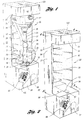
- FIG. 1 shows an open face display carton and motorized implement arrangement 20, made in accordance with the present invention.
- Display arrangement 20 comprises an open face carton 22 which retains a motorized implement, which in this exemplary embodiment, is line trimmer 24, which is hand carriable.
- Line trimmer 24 is shown in a two-piece disassembled configuration retained within carton 22. The majority of line trimmer 24 is tactiley accessible by a purchaser as is readily apparent from FIG. 1. Further, as line trimmer 24 is partially disassembled, the overall height of carton 22 is substantially reduced over that which would be required to retain line trimmer 24 if it were fully assembled.
- Tool portion 26 has a second boom section 42 which may be operatively connected to first boom section 28 by simply telescopically inserting second boom section 42 into connector 40.
- Tool portion 26 includes a distal end 44 and a tool 46, both of which are retained in carton 22.
- tool 46 includes a line trimmer head 48 having a line advance button 49 at the end thereof. Line advance button 49 is shown, in phantom, being retained by carton 22 in FIG. 5.
- a guard 50 is fastened to line trimmer head 48.
- FIG. 2 shows carton 22 without line trimmer 24 being mounted therein.
- Carton 22 comprises a main body 52, an upper insert 54 and a lower insert 56, which are shown partially assembled in FIG. 3.
- Upper and lower inserts 54 and 56 are retained within respective upper and lower portions of main body 52.
- Respective FIGS. 6,7 and 8, illustrate main body 52, upper insert 54 and lower insert 56 prior to their being folded into individual interlocking configurations as shown in FIG. 3.
- lower insert 56 includes a large retaining aperture 58 and a smaller retaining aperture 60. Connected to smaller retaining aperture 60 is a flap 62 which is hingedly connected to the remainder of lower insert 56. Respective motorized and tool portions 25 and 26 are placed through the top of main body 52 with distal end 38 and connector 40 of motorized portion 25 and button 49 of line trimmer head 48 passing through respective retaining apertures 58 and 60. Flap 62 swings out of the way to allow connector 40 to pass through the top of lower insert 56. Distal end 36 of motorized portion 25 rests atop lower insert 56. FIG. 5 illustrates portions of first boom section 28 and button 49 of line trimmer head 48 being retained within retaining apertures 58 and 60. Lower insert 56 also has a second retaining aperture 61 spaced below and aligned with retaining aperture 60. Distal end 38 is also supported by retaining aperture 61.
- a visual access opening 53 At the lower front of carton 22 is a visual access opening 53.
- lower insert 56 has a rectangular opening 64 defined therein.
- visual access opening 53 of main body 52 is aligned with rectangular opening 64 of lower insert 56. Accordingly, a purchaser can look through visual access opening 53 and aligned rectangular opening 64 and view connector 40.
- the dashed line 53' in FIG. 5 shows the alignment of visual access opening 53 relative to a rectangular space 64' defined by walls of lower insert 56.
- indicia 66 is added to the lower portion of carton 22 to induce the purchaser to look through visual access opening 53.
- main body 52 includes a D-shaped retaining aperture 70 for holding distal end 44 of tool portion 26. Also formed in main body 52 are a pair of retaining slots 72 and 74 which cooperate to clamp about guard 50 of tool portion 26. After line advance button 49 is placed within retaining aperture 58, guard 50 is placed through retaining slots 72 and 74. Distal end 44 of tool portion 26 is then pressed through retaining aperture 70 thereby retaining tool portion 26 in carton 22.
- upper insert 54 has a motor retaining opening 76 which is configured to fit about the upper portion of motor 27.
- Motor 27 is shown in FIG. 4, in phantom, being retained within motor retaining opening 76 in upper insert 54.
- top insert 54 is passed through a top opening in main body 52 with motor retaining opening 76 fitting over the top portion of motor 27.
- Top and bottom flaps on main body 52 are then stapled or otherwise secured together thus retaining line trimmer 24 in carton 22 and forming display arrangement 20.
- Motorized and tool portions 25 and 26 are located adjacent one another and preferably are oriented in a generally upright position. Purchasers can readily see the majority of the intermediate portions of motorized and tool portions 25 and 26 for their appraisal in making a determination of whether or not to purchase the line trimmer 24 held within carton 22. This appraisal can take the form of not only a visual evaluation but also a tactile assessment of the majority of line trimmer 24 due to carton 22's open face construction. Further, the purchaser can view connector 40 through visual access opening 53 of main body 52 and rectangular opening 64 of lower insert 56. In conjunction with descriptive indicia 66, a purchaser can also readily appreciate that line trimmer 24 can be quickly assembled by simply inserting second boom section 42 into connector 40.
- line trimmer 24 is disassembled into two pieces, i.e., motorized and tool portions 25 and 26, the overall height of carton 22 is only slightly greater than the longer of the two motorized and tool portions 25 and 26, which this case is motorized portion 25. Consequently, arrangement 20 provides for a more compact packaging of line trimmer 24 than has been available in previous open face display carton and motorized implement arrangements.
- main body 52 can be made without a visual access opening and without any advertising or informational indicia such as indicia 66.
- Back panel 90 is physically separated from inner panel 86 as indicated by the solid cut line therebetween.
- Outer panels 82 and 84 are generally C-shaped, and when main body 52 is fully constructed, extend forwardly from rear panel 80.
- Radiused contours 83 and 85 are formed on outer panels 82 and 84, located above the top inner panels 86 and 88. The presence of contours 83 and 85 significantly improve the strength and tear resistance of outer panels 82 and 84 relative to having corners which are right angles.
- Contours 83 and 85 each have approximately a one inch (25.4mm) radius.
- Upper front panel 92 and lower front panel 94 will lie generally parallel to and spaced forwardly of rear panel 80.
- Inner panels 86 and 88 extend rearwardly from outer panel 82 and 84 toward rear panel 80 and interlock with one another.
- Back panel 90 connected to inner panel 88 will overlie rear panel 80.
- Upper flaps 96 and lower flaps 98 are also provided on main body 52 and cooperate to form respective top and bottom walls 100 and 102, as shown in FIG. 1.
- the portions of main body 52 above and below inner panels 86 and 88 can be considered to be upper and lower portions of main body 52.
- the remaining intermediate portion is a central portion of main body 52.
- Main body 52 when fully constructed, is generally C-shaped in side view, as suggested in FIG. 2.
- outer panel 82 is folded forwardly from rear panel 80. Upper and lower front panels 92 and 94 are then folded from right to the left as viewed in FIG. 3. Finally, outer panel 84 is folded rearwardly from upper front panel 92 and lower front panel 94. Although not shown, glue panel 95 is covered with glue and placed within and adjacent to rear panel 80 to hold main body 52 peripherally together in a rectangular configuration. Inner panel 86 is then folded rearwardly from outer panel 82 toward rear panel 80. Similarly, inner panel 88 is folded rearwardly from outer panel 82 with inner panels 86 and 88 interlocking with one another. As a result, back panel 90 lies adjacent and parallel to rear panel 80 extending from inner panel 88 toward outer panel 82.
- flaps 96 can be folded over one anther as indicated in FIG. 3 and glued or stapled together to produce top wall 100 of carton 22.
- bottom panels 98 are folded over one another and fastened together to form bottom wall 102 allowing carton 22 to stand in an upright orientation.
- top insert 54 is shown.
- the major panels of top insert 54 include a bottom panel 110, vertical side panels 112 and 114, top panels 116 and 118, vertical web panels 120 and 122 and overlying panels 124 and 126. Also included are a back panel 128 and an overlying top panel 130. Tabs 132, 134, 136 and 138 are attached to respective overlying top panels 130 and web panels 120 and 122 and help interlock top insert 54 together.
- overlying panels 124 and 126 overlie bottom panel 110.
- Contoured openings 140 and 142 in respective overlying panels 124 and 126 are aligned with opening 76 of bottom panel 110. Opening 76 is contoured to match the horizontal profile of motor 26.
- web panels 120 and 122 have contours 144 and 146 which form a vertical contour which overlies the top profile of motor 27.
- the visual access opening 53 has been described and illustrated as being located in the lower portion of the main body it is possible for a visual access opening 53 to be located on the upper portion of the main body or on both the lower and upper portions of the main body.
Landscapes
- Engineering & Computer Science (AREA)
- Mechanical Engineering (AREA)
- Cartons (AREA)
- Packaging Of Machine Parts And Wound Products (AREA)
Description
- This invention relates to open face display cartons which retain and display motorized implements therein.
- Open face cartons for retaining and displaying motorized implements are known. Examples include U.S. Patents Nos. 5,495,937 and 5,332,085. In these patents, motorized implements such as line trimmers and vacuum cleaners are fully assembled and displayed within open face cartons. The line trimmers are generally ready to use once they are removed from the carton. The open face design allows potential purchasers to view and tactiley access the line trimmer at a point of purchase. This presents a substantial sales advantage over comparable products which are packaged completely hidden within closed boxes.
- The open face cartons described above have a couple of drawbacks. As the line trimmers are of a substantial height when fully assembled, the open face cartons are also quite tall. This can provide problems during shipping and also during display on store shelves. Further, end portions of the line trimmers are held by inserts within the open face display cartons. While the vast majority of an overall line trimmer is exposed for the purchaser's examination and consideration, the end portions held within the inserts are hidden from the purchaser's view. These portions often contain some of the most interesting and saleable features of the line trimmer or like motorized implement.
- The present invention addresses these drawbacks.
- It is an object of the present invention to provide an open face display carton and motorized implement arrangement which is reduced in height yet provides ready visual inspection of highly desirable sales features of a motorized implement even though the desirable sales features are retained within inserts and are not visible through an open region or face of the open face display carton.
- It is another object to provide a compact open face display carton and motorized implement arrangement wherein the motorized implement is disassembled into two elongate portions which are disposed upright adjacent one another and have ends which are held within inserts, of the display carton while most of the elongate portions are still tactiley accessible in an open region of the display carton.
- It is a further object of the present invention to provide an open face display carton and motorized implement arrangement which has ends of the motorized implement retained within upper and lower portions of the display carton while the centre portion of the motorized implement is tactiley accessible in an intermediate open region and wherein at least one of the upper and lower portions of the display carton has a visual access opening providing visual access to a retained end of the motorized implement.
- In accordance with the invention, there is provided an open face carton and implement display arrangement comprising:
- an operator carriable motorized implement including a motorized portion having a motor and a tool portion having a tool, and
- a display carton having a main body and upper
and lower inserts, the profile of the main body being
generally C-shaped having a central portion and top and
bottom portions which protrude forwardly from the
central portion, the top and bottom portions retaining
the upper and lower inserts therein, the main body
having a rear panel, a pair of outer panels which
extend forwardly from the rear panel and a pair of
inner panels which extend from the outer panels toward
the rear panel defining an open region between the
inner panels; characterised in that:
- the motorized portion has a first boom section extending from the motor and having a first end, the tool portion has a second boom section extending from the tool and having a second end;
- the motorized implement further comprises a connector attached to one of the first and second ends for operatively connecting the first and second boom sections together;
- the motorized implement is disassembled into its motorized portion and tool portion; and
- the respective motorized and tool portions are retained in generally adjacent upright positions by the carton with at least a portion of each of the motorized and tool portions being tactiley accessible within the open region of the carton and the carton being slightly larger in height than the longer of the motorized and tool portions and substantially less in height that the fully assembled motorized implement.
-
- By way of example only a specific embodiment of the present invention will now be described, with reference to the accompanying drawings, in which:-
- FIGURE 1 is a perspective view of an embodiment of open face display carton and motorized implement arrangement made in accordance with the present invention;
- FIGURE 2 is a perspective view of the display carton without the motorized implement therein;
- FIGURE 3 is an exploded perspective view of a partially assembled display carton including an upper insert, a lower insert and a main body;
- FIGURE 4 is a fragmentary sectional view taken along line 4-4 of FIG. 2;
- FIGURE 5 is a fragmentary sectional view taken along line 5-5 of FIG. 2;
- FIGURE 6 is a plan view of the unfolded main body;
- FIGURE 7 is a plan view of the unfolded top insert; and
- FIGURE 8 is a plan view of the unfolded bottom insert.
-
- FIG. 1 shows an open face display carton and motorized
implement arrangement 20, made in accordance with the present invention.Display arrangement 20 comprises anopen face carton 22 which retains a motorized implement, which in this exemplary embodiment, is line trimmer 24, which is hand carriable.Line trimmer 24 is shown in a two-piece disassembled configuration retained withincarton 22. The majority ofline trimmer 24 is tactiley accessible by a purchaser as is readily apparent from FIG. 1. Further, asline trimmer 24 is partially disassembled, the overall height ofcarton 22 is substantially reduced over that which would be required to retainline trimmer 24 if it were fully assembled. -
Line trimmer 24 includes a motorizedportion 25 and a tool portion 26. Motorizedportion 25 has amotor 27 and afirst boom section 28 extending frommotor 27. Ahandle 30 is clampingly connected by aclamp 32 tofirst boom section 28.Handle 30 is generally C-shaped having a foam coveredgrip 34 and adistal end 36 which extends throughclamp 32. Also mounted onfirst boom section 28 is atrigger mechanism 37 which controls the operation ofline trimmer 24. As indicated in phantom in FIG. 5,first boom section 28 also has adistal end 38 to which a telescopicquick release connector 40 is mounted.Connector 40 is more fully described in U.S. patent application serial number 08/303,320, entitled "Attachment System For A Battery Powered Tool" which is hereby incorporated by reference. - Tool portion 26 has a
second boom section 42 which may be operatively connected tofirst boom section 28 by simply telescopically insertingsecond boom section 42 intoconnector 40. Tool portion 26 includes adistal end 44 and a tool 46, both of which are retained incarton 22. In this exemplary embodiment, tool 46 includes aline trimmer head 48 having aline advance button 49 at the end thereof.Line advance button 49 is shown, in phantom, being retained bycarton 22 in FIG. 5. A guard 50 is fastened toline trimmer head 48. - FIG. 2 shows
carton 22 without line trimmer 24 being mounted therein.Carton 22 comprises amain body 52, anupper insert 54 and alower insert 56, which are shown partially assembled in FIG. 3. Upper andlower inserts main body 52. Respective FIGS. 6,7 and 8, illustratemain body 52,upper insert 54 andlower insert 56 prior to their being folded into individual interlocking configurations as shown in FIG. 3. - Referring to FIG. 3,
lower insert 56 includes a largeretaining aperture 58 and a smallerretaining aperture 60. Connected tosmaller retaining aperture 60 is aflap 62 which is hingedly connected to the remainder oflower insert 56. Respective motorized andtool portions 25 and 26 are placed through the top ofmain body 52 withdistal end 38 andconnector 40 of motorizedportion 25 andbutton 49 ofline trimmer head 48 passing throughrespective retaining apertures connector 40 to pass through the top oflower insert 56.Distal end 36 of motorizedportion 25 rests atoplower insert 56. FIG. 5 illustrates portions offirst boom section 28 andbutton 49 ofline trimmer head 48 being retained within retainingapertures Lower insert 56 also has asecond retaining aperture 61 spaced below and aligned with retainingaperture 60.Distal end 38 is also supported by retainingaperture 61. - At the lower front of
carton 22 is a visual access opening 53. Similarly,lower insert 56 has arectangular opening 64 defined therein. Whenlower insert 56 is properly positioned withincarton 22, visual access opening 53 ofmain body 52 is aligned withrectangular opening 64 oflower insert 56. Accordingly, a purchaser can look through visual access opening 53 and alignedrectangular opening 64 andview connector 40. The dashed line 53' in FIG. 5 shows the alignment of visual access opening 53 relative to a rectangular space 64' defined by walls oflower insert 56. To encourage a purchaser to view a particular feature of interest observable through visual access opening 53, which in this exemplary embodiment isconnector 40,indicia 66 is added to the lower portion ofcarton 22 to induce the purchaser to look throughvisual access opening 53. - Looking to FIG. 3,
main body 52 includes a D-shaped retainingaperture 70 for holdingdistal end 44 of tool portion 26. Also formed inmain body 52 are a pair of retainingslots line advance button 49 is placed within retainingaperture 58, guard 50 is placed through retainingslots Distal end 44 of tool portion 26 is then pressed through retainingaperture 70 thereby retaining tool portion 26 incarton 22. - As best seen in FIG. 3,
upper insert 54 has amotor retaining opening 76 which is configured to fit about the upper portion ofmotor 27.Motor 27 is shown in FIG. 4, in phantom, being retained withinmotor retaining opening 76 inupper insert 54. After tool portion 26 is secured withinmain body 52 anddistal end 38 ofmotor portion 25 is retained withinlower insert 56,top insert 54 is passed through a top opening inmain body 52 withmotor retaining opening 76 fitting over the top portion ofmotor 27. Top and bottom flaps onmain body 52 are then stapled or otherwise secured together thus retainingline trimmer 24 incarton 22 and formingdisplay arrangement 20. - Motorized and
tool portions 25 and 26 are located adjacent one another and preferably are oriented in a generally upright position. Purchasers can readily see the majority of the intermediate portions of motorized andtool portions 25 and 26 for their appraisal in making a determination of whether or not to purchase theline trimmer 24 held withincarton 22. This appraisal can take the form of not only a visual evaluation but also a tactile assessment of the majority ofline trimmer 24 due tocarton 22's open face construction. Further, the purchaser can viewconnector 40 through visual access opening 53 ofmain body 52 andrectangular opening 64 oflower insert 56. In conjunction withdescriptive indicia 66, a purchaser can also readily appreciate thatline trimmer 24 can be quickly assembled by simply insertingsecond boom section 42 intoconnector 40. Further, becauseline trimmer 24 is disassembled into two pieces, i.e., motorized andtool portions 25 and 26, the overall height ofcarton 22 is only slightly greater than the longer of the two motorized andtool portions 25 and 26, which this case is motorizedportion 25. Consequently,arrangement 20 provides for a more compact packaging ofline trimmer 24 than has been available in previous open face display carton and motorized implement arrangements. In the event that packaging engineers or marketing personnel believe that visual access to a particular feature, such asconnector 40, is not necessary or appropriate,main body 52 can be made without a visual access opening and without any advertising or informational indicia such asindicia 66. - The particular die cut blanks forming
main body 52,upper insert 54 andlower insert 56 will now be described in greater detail as will be their folded construction. Dashed lines in FIGS. 6-8 indicate fold lines. Referring to FIG. 6, the die cut blank 52' used to constructmain body 52 is shown. Major components ofmain body 52 include arear panel 80, first and secondouter panels inner panels panel 90 and upper and lowerfront panels narrow glue panel 95 is attached toouter panel 84. -
Back panel 90 is physically separated frominner panel 86 as indicated by the solid cut line therebetween.Outer panels main body 52 is fully constructed, extend forwardly fromrear panel 80.Radiused contours outer panels inner panels contours outer panels Contours front panel 92 and lowerfront panel 94 will lie generally parallel to and spaced forwardly ofrear panel 80.Inner panels outer panel rear panel 80 and interlock with one another.Back panel 90, connected toinner panel 88 will overlierear panel 80.Upper flaps 96 andlower flaps 98 are also provided onmain body 52 and cooperate to form respective top andbottom walls main body 52 above and belowinner panels main body 52. The remaining intermediate portion is a central portion ofmain body 52.Main body 52, when fully constructed, is generally C-shaped in side view, as suggested in FIG. 2. - Looking to FIG. 3,
outer panel 82 is folded forwardly fromrear panel 80. Upper and lowerfront panels outer panel 84 is folded rearwardly from upperfront panel 92 and lowerfront panel 94. Although not shown,glue panel 95 is covered with glue and placed within and adjacent torear panel 80 to holdmain body 52 peripherally together in a rectangular configuration.Inner panel 86 is then folded rearwardly fromouter panel 82 towardrear panel 80. Similarly,inner panel 88 is folded rearwardly fromouter panel 82 withinner panels panel 90 lies adjacent and parallel torear panel 80 extending frominner panel 88 towardouter panel 82. Afterupper insert 54 is inserted into the open top ofmain body 52, flaps 96 can be folded over one anther as indicated in FIG. 3 and glued or stapled together to producetop wall 100 ofcarton 22. Similarly,bottom panels 98 are folded over one another and fastened together to formbottom wall 102 allowingcarton 22 to stand in an upright orientation. - Referring now to FIGS. 3, 4 and 7,
top insert 54 is shown. The major panels oftop insert 54 include abottom panel 110,vertical side panels top panels vertical web panels overlying panels back panel 128 and an overlyingtop panel 130.Tabs top panels 130 andweb panels top insert 54 together. Whentop insert 54 is fully assembled, overlyingpanels bottom panel 110.Contoured openings overlying panels bottom panel 110.Opening 76 is contoured to match the horizontal profile of motor 26. Similarly,web panels contours motor 27. - Finally,
bottom insert 56 is shown in FIGS. 3, 5 and 8. Referring specifically to FIG. 8,bottom insert 56 includes atop panel 150, verticalrear panel 152,vertical side panels front panels top panel 150 arevertical side panels front panel 166. Retainingapertures flap 62 are formed intop panel 150. Ahorizontal panel 168 will extend parallel totop panel 150 with retainingaperture 61 being coaxially aligned with retainingaperture 60 intop panel 150. Flaps adjacent retainingaperture 61 accommodateconnector 40 passing through retainingaperture 61.Tabs slots bottom insert 56.Bottom insert 56 is shown in a folded configuration in FIGS. 3 and 5. - While in the foregoing specification this invention has been described in relation to a certain preferred embodiment thereof, and many details have been set forth for the purpose of illustration, it will be apparent to those skilled in the art that the invention is susceptible to alteration and that certain other details described herein can vary considerably without departing from the scope of the invention.
- For example, although the visual access opening 53 has been described and illustrated as being located in the lower portion of the main body it is possible for a visual access opening 53 to be located on the upper portion of the main body or on both the lower and upper portions of the main body.
Claims (9)
- An open face carton (22) and implement display arrangement (20) comprising:an operator carriable motorized implement (24) including a motorized portion (25) having a motor (27) and a tool portion (26) having a tool (46), anda display carton (22) having a main body (52) and upper (54) and lower (56) inserts, the profile of the main body being generally C-shaped having a central portion and top and bottom portions which protrude forwardly from the central portion, the top and bottom portions retaining the upper (54) and lower (56) inserts therein, the main body having a rear panel (80), a pair of outer panels (82,84) which extend forwardly from the rear panel and a pair of inner panels (86,88) which extend from the outer panels toward the rear panel defining an open region between the inner panels; characterised in that:the motorized portion has a first boom section (28) extending from the motor and having a first end (38), the tool portion has a second boom section (42) extending from the tool and having a second end (44);the motorized implement further comprises a connector (40) attached to one of the first and second ends for operatively connecting the first and second boom sections together;the motorized implement is disassembled into its motorized portion and tool portion; andthe respective motorized (25) and tool (26) portions are retained in generally adjacent upright positions by the carton with at least a portion of each of the motorized and tool portions being tactiley accessible within the open region of the carton and the carton being slightly larger in height than the longer of the motorized and tool portions and substantially less in height than the fully assembled motorized implement.
- An arrangement as claimed in claim 1, wherein:
one of the lower and upper portions of the main body has a visual access opening (53) therein for displaying one of the motor (27) and the tool (26) and the first (38) and second (44) ends of the motorized and tool portions. - An arrangement as claimed in claim 1 or claim 2, wherein:
one of the upper and lower portions of the main body has a visual access opening (53) therein spaced from the open region of the connector (40) is retained within one of the inserts and is visible through the visual access opening. - An arrangement as claimed in claim 1, wherein the connector (40) is affixed at the first end (38) of the first boom section (28) and is retained within the lower insert (56).
- An arrangement as claimed in claim 4, wherein:
the bottom portion of the main body (52) has the visual access opening (53) therein which allows a point-of-sale purchaser to view the connector (40). - An arrangement as claimed in claim 5, wherein:
the lower insert (56) has a further visual access opening (64) therein in alignment with the visual access opening (53) of the main body. - An arrangement as claimed in the preceding claims 4 to 6, wherein:
the second end (44) of the tool portion is retained within a retaining aperture (70) in one of the inner panels (88). - An arrangement as claimed in the preceding claims 4 to 7, wherein:
the lower insert (56) has a pair of spaced apart retaining openings (58,60) which respectively retain the tool (26) and the connector (40). - An arrangement as claimed in the preceding claims 4 to 8, wherein:
the motor (27) is at least partially retained within the upper insert (54).
Applications Claiming Priority (2)
| Application Number | Priority Date | Filing Date | Title |
|---|---|---|---|
| US08/685,816 US5676248A (en) | 1996-07-25 | 1996-07-25 | Open face display carton and motorized implement arrangement |
| US685816 | 1996-07-25 |
Publications (2)
| Publication Number | Publication Date |
|---|---|
| EP0820935A1 EP0820935A1 (en) | 1998-01-28 |
| EP0820935B1 true EP0820935B1 (en) | 2001-10-10 |
Family
ID=24753789
Family Applications (1)
| Application Number | Title | Priority Date | Filing Date |
|---|---|---|---|
| EP97305614A Expired - Lifetime EP0820935B1 (en) | 1996-07-25 | 1997-07-25 | Open face display carton and motorized implement arrangement |
Country Status (4)
| Country | Link |
|---|---|
| US (1) | US5676248A (en) |
| EP (1) | EP0820935B1 (en) |
| JP (1) | JPH1077030A (en) |
| DE (1) | DE69707212T2 (en) |
Families Citing this family (7)
| Publication number | Priority date | Publication date | Assignee | Title |
|---|---|---|---|---|
| US5941384A (en) * | 1998-01-09 | 1999-08-24 | The Toro Company | Container for an article of hand-held power equipment |
| USD468636S1 (en) | 2002-01-25 | 2003-01-14 | Emhart Llc | Tubular packaging |
| USD528409S1 (en) * | 2003-09-05 | 2006-09-19 | Master Lock Company | Hitch lock packaging |
| USD536612S1 (en) * | 2006-01-20 | 2007-02-13 | Microsoft Corporation | Package for an input device |
| US20110000811A1 (en) * | 2009-07-02 | 2011-01-06 | Dayan Maurice S | Clamshell package for holding and displaying consumer products |
| US9475637B2 (en) * | 2015-07-30 | 2016-10-25 | Caterpillar Inc. | Packaged assembly for machine implement |
| CN113023028A (en) * | 2019-12-25 | 2021-06-25 | 苏州佳世达电通有限公司 | Packing box and display assembly |
Family Cites Families (22)
| Publication number | Priority date | Publication date | Assignee | Title |
|---|---|---|---|---|
| US2291645A (en) * | 1939-06-14 | 1942-08-04 | American Can Co | Method of packaging articles |
| US2727620A (en) * | 1952-12-29 | 1955-12-20 | Sutherland Paper Co | Collapsible display carton |
| US2752035A (en) * | 1953-10-12 | 1956-06-26 | Daniel S Shinoda | Floral packaging unit |
| US3481453A (en) * | 1968-02-23 | 1969-12-02 | Black & Decker Mfg Co | Display carton for power tools and the like |
| US3570658A (en) * | 1969-08-08 | 1971-03-16 | Union Camp Corp | Shadow box display carton |
| DK122037B (en) * | 1970-08-10 | 1972-01-10 | Nyborg Plast | Packaging with a number of goods units enclosed by shrink film and method of its manufacture. |
| US3669253A (en) * | 1970-12-30 | 1972-06-13 | Weyerhaeuser Co | Display carton with inner shelf panel and an article holding feature |
| US3741380A (en) * | 1971-06-23 | 1973-06-26 | Ass Packaging Inc | Shock absorbing paperboard package |
| US3747835A (en) * | 1971-12-21 | 1973-07-24 | Olinkraft Inc | Wrap-around article carrier with secondary retention end panels |
| US3747831A (en) * | 1972-05-23 | 1973-07-24 | Champion Int Corp | Folding carton with partition and blank therefor |
| US3874500A (en) * | 1973-07-03 | 1975-04-01 | Thomas H Nicholl | Display package |
| US3929225A (en) * | 1974-12-09 | 1975-12-30 | Hoerner Waldorf Corp | Short bicycle pack |
| US4171050A (en) * | 1978-05-01 | 1979-10-16 | Container Corporation Of America | Packaging structure |
| US4287991A (en) * | 1979-04-02 | 1981-09-08 | Donnelly Bernard P | Modularized unit load and disposable pallet therefor |
| US4247003A (en) * | 1979-05-09 | 1981-01-27 | Dutton-Lainson Company | Product display card |
| US4354598A (en) * | 1981-08-24 | 1982-10-19 | Champion International Corporation | Article display package and blank therefor |
| US4549654A (en) * | 1983-05-31 | 1985-10-29 | Champion International Corporation | Article display package and blank therefor |
| US4848563A (en) * | 1987-12-17 | 1989-07-18 | Robbins Sports | Display package and method of manufacture |
| US5048677A (en) * | 1988-05-20 | 1991-09-17 | Rayovac Corporation | Display package |
| US4915224A (en) * | 1989-06-20 | 1990-04-10 | Bekind, Inc. | Container for packaging a flower |
| US5114002A (en) * | 1991-06-03 | 1992-05-19 | Universal Folding Box, Inc. | Reinforced display box |
| US5332085A (en) * | 1993-01-19 | 1994-07-26 | Ryobi Outdoor Products | Shipping and display container for lawn implement |
-
1996
- 1996-07-25 US US08/685,816 patent/US5676248A/en not_active Expired - Fee Related
-
1997
- 1997-07-25 JP JP9215652A patent/JPH1077030A/en active Pending
- 1997-07-25 DE DE69707212T patent/DE69707212T2/en not_active Expired - Fee Related
- 1997-07-25 EP EP97305614A patent/EP0820935B1/en not_active Expired - Lifetime
Also Published As
| Publication number | Publication date |
|---|---|
| JPH1077030A (en) | 1998-03-24 |
| US5676248A (en) | 1997-10-14 |
| DE69707212D1 (en) | 2001-11-15 |
| EP0820935A1 (en) | 1998-01-28 |
| DE69707212T2 (en) | 2002-05-02 |
Similar Documents
| Publication | Publication Date | Title |
|---|---|---|
| US5826727A (en) | Shipping and display container for motorized implement | |
| US5375700A (en) | Cutlery and accessory packaging and display carton | |
| US5622258A (en) | Interactive packaging system | |
| US4570787A (en) | Display device | |
| US5826781A (en) | Identification button for paperboard container | |
| EP1204558B1 (en) | Easy to open display container | |
| USD373723S (en) | Package | |
| USD372670S (en) | Package | |
| US6247589B1 (en) | Container for an article of hand-held power equipment | |
| US5464149A (en) | H-partition and display case | |
| US5676248A (en) | Open face display carton and motorized implement arrangement | |
| US3292290A (en) | Display unit | |
| CA1088469A (en) | Product display card | |
| CA2607736A1 (en) | Variable volume carton | |
| US1929490A (en) | Box | |
| US4416369A (en) | Display and dispensing carton | |
| CA2084237C (en) | Package for safety razors | |
| CA2304671C (en) | Folded cardboard article for packaging spurs | |
| US2507404A (en) | Carton | |
| US4729477A (en) | Food scoop with sealed prize chamber | |
| US4907693A (en) | Convertible shipping carton | |
| US20240076096A1 (en) | Display ready carton | |
| US5566820A (en) | Dust mop package | |
| US4826006A (en) | Quick packing for displaying in large-scale distribution outlets and for transporting products as flue-brushes | |
| JPH074175Y2 (en) | Carton with hanger |
Legal Events
| Date | Code | Title | Description |
|---|---|---|---|
| PUAI | Public reference made under article 153(3) epc to a published international application that has entered the european phase |
Free format text: ORIGINAL CODE: 0009012 |
|
| AK | Designated contracting states |
Kind code of ref document: A1 Designated state(s): AT BE CH DE DK ES FI FR GB GR IE IT LI LU MC NL PT SE |
|
| AX | Request for extension of the european patent |
Free format text: AL;LT;LV;RO;SI |
|
| 17P | Request for examination filed |
Effective date: 19980706 |
|
| RBV | Designated contracting states (corrected) |
Designated state(s): AT BE CH DE LI |
|
| 17Q | First examination report despatched |
Effective date: 19990701 |
|
| GRAG | Despatch of communication of intention to grant |
Free format text: ORIGINAL CODE: EPIDOS AGRA |
|
| GRAG | Despatch of communication of intention to grant |
Free format text: ORIGINAL CODE: EPIDOS AGRA |
|
| GRAH | Despatch of communication of intention to grant a patent |
Free format text: ORIGINAL CODE: EPIDOS IGRA |
|
| GRAH | Despatch of communication of intention to grant a patent |
Free format text: ORIGINAL CODE: EPIDOS IGRA |
|
| RAP1 | Party data changed (applicant data changed or rights of an application transferred) |
Owner name: MTD PRODUCTS INC. |
|
| ITF | It: translation for a ep patent filed | ||
| GRAA | (expected) grant |
Free format text: ORIGINAL CODE: 0009210 |
|
| AK | Designated contracting states |
Kind code of ref document: B1 Designated state(s): DE FR GB IT |
|
| REF | Corresponds to: |
Ref document number: 69707212 Country of ref document: DE Date of ref document: 20011115 |
|
| REG | Reference to a national code |
Ref country code: GB Ref legal event code: IF02 |
|
| ET | Fr: translation filed | ||
| PG25 | Lapsed in a contracting state [announced via postgrant information from national office to epo] |
Ref country code: GB Free format text: LAPSE BECAUSE OF NON-PAYMENT OF DUE FEES Effective date: 20020725 |
|
| PLBE | No opposition filed within time limit |
Free format text: ORIGINAL CODE: 0009261 |
|
| STAA | Information on the status of an ep patent application or granted ep patent |
Free format text: STATUS: NO OPPOSITION FILED WITHIN TIME LIMIT |
|
| 26N | No opposition filed | ||
| PG25 | Lapsed in a contracting state [announced via postgrant information from national office to epo] |
Ref country code: DE Free format text: LAPSE BECAUSE OF NON-PAYMENT OF DUE FEES Effective date: 20030201 |
|
| GBPC | Gb: european patent ceased through non-payment of renewal fee |
Effective date: 20020725 |
|
| PG25 | Lapsed in a contracting state [announced via postgrant information from national office to epo] |
Ref country code: FR Free format text: LAPSE BECAUSE OF NON-PAYMENT OF DUE FEES Effective date: 20030331 |
|
| REG | Reference to a national code |
Ref country code: FR Ref legal event code: ST |
|
| PG25 | Lapsed in a contracting state [announced via postgrant information from national office to epo] |
Ref country code: IT Free format text: LAPSE BECAUSE OF NON-PAYMENT OF DUE FEES Effective date: 20050725 |