EP0819935B1 - A catalytic gas sensor element - Google Patents
A catalytic gas sensor element Download PDFInfo
- Publication number
- EP0819935B1 EP0819935B1 EP19960111696 EP96111696A EP0819935B1 EP 0819935 B1 EP0819935 B1 EP 0819935B1 EP 19960111696 EP19960111696 EP 19960111696 EP 96111696 A EP96111696 A EP 96111696A EP 0819935 B1 EP0819935 B1 EP 0819935B1
- Authority
- EP
- European Patent Office
- Prior art keywords
- silicon
- gas sensor
- catalytic gas
- heating
- layer
- Prior art date
- Legal status (The legal status is an assumption and is not a legal conclusion. Google has not performed a legal analysis and makes no representation as to the accuracy of the status listed.)
- Expired - Lifetime
Links
Images

Classifications
-
- G—PHYSICS
- G01—MEASURING; TESTING
- G01N—INVESTIGATING OR ANALYSING MATERIALS BY DETERMINING THEIR CHEMICAL OR PHYSICAL PROPERTIES
- G01N27/00—Investigating or analysing materials by the use of electric, electrochemical, or magnetic means
- G01N27/02—Investigating or analysing materials by the use of electric, electrochemical, or magnetic means by investigating impedance
- G01N27/04—Investigating or analysing materials by the use of electric, electrochemical, or magnetic means by investigating impedance by investigating resistance
- G01N27/14—Investigating or analysing materials by the use of electric, electrochemical, or magnetic means by investigating impedance by investigating resistance of an electrically-heated body in dependence upon change of temperature
- G01N27/16—Investigating or analysing materials by the use of electric, electrochemical, or magnetic means by investigating impedance by investigating resistance of an electrically-heated body in dependence upon change of temperature caused by burning or catalytic oxidation of surrounding material to be tested, e.g. of gas
Definitions
- the present invention refers to a catalytic gas sensor element used for a qualitative and quantitative detection of gases.
- Catalytic gas sensors which include noble metals with the aid of which potentially present gases are detected qualitatively and quantitatively.
- a catalyst normally a noble metal
- a carrier e.g. a membrane.
- the other side of the carrier has arranged thereon heating and detection elements.
- the heating elements are used for the purpose of heating the catalyst to a specific temperature. If a gas is present in the atmosphere surrounding the noble metal, said gas will react with the catalyst, whereby an increase in temperature will be caused. This increase in temperature is then detected by means of a temperature detection element.
- a resistor is used as a heating element, e.g. a thin film resistor applied to the carrier in the form of a meander, this resistor, whose resistivity changes as the temperature changes, can also be used as a temperature detection element.
- Catalytic gas sensors of the type described hereinbefore show little stability and high poisoning and ageing effects in addition to other disadvantages.
- EP-A-0446483 relates to a catalytic gas sensor comprising a diaphragm supported by a support structure of silicon. On a main surface of the diaphragm opposite to the support structure, a catalytically active layer is provided for detecting the presence of a gas. In addition, heating means are provided in order to warm up different portions of the active layer to different temperatures. Temperature sensing means are provided for sensing the temperature of the different portions.
- EP-A-0703449 relates to a catalytic calorimetric gas sensor including a sol-gel processed washcoat and sol-processed catalytically active metal particels deposited on the washcoat with high surface area and controlled porosity which increases the sensitivity, durability and reproducibility of the sensor.
- a membrane having a low thermal conductivity is supported by a silicon frame on one main surface thereof.
- Temperature measuring layers are provided on the second surface of the membrane. The temperature measuring layers are covered by a passivation layer.
- catalytic layers are provided which are separated from the temperature measuring layers by the passivation layer.
- the detection element of the catalytic gas sensor according to the present invention which consists of a microporous material has preferably a large surface, and this results in high sensitivity and stability and little poisoning and ageing effects. It follows that less easily oxidized molecules, e.g. methane, can be detected.
- a carrier, to which the detection element is attached is preferably a silicon free membrane, and, therefore, less heat is lost and power consumption is low.
- a catalytic gas sensor element according to the present invention can preferably be produced by means of micromachining techniques. The specific features resulting from this type of production are batch processing, easy arraying, a high sensitivity and a speedy response.
- Fig. 1 shows a preferred embodiment of a catalytic gas sensor element according to the present invention, which is adapted to be produced by means of micromachining techniques.
- a detection element 10 is attached to the bottom side of a carrier membrane 12.
- the detection element 10 of the preferred embodiment consists of a microporous p-type silicon block, the bottom side of which is impregnated with a catalytically active noble metal.
- the membrane 12 of the preferred embodiment consists of silicon carbide.
- the bottom side of said membrane 12 has additionally attached thereto holding means 14, 16; the holding means of the preferred embodiment consists of a frame out of silicon and are produced during the micromachining of the catalytic gas sensor element, as will be explained hereinbelow.
- the top side of the membrane 12 of the preferred embodiment has provided thereon metallic resistance structures 18, which are used for heating the detection element 10 as well as for temperature measurement.
- the metallic structures 18 can be applied to the membrane 12 e.g. in the form of a meander.
- the resistance structures may, for example, only comprise one resistance film used as a heating element and also as a temperature detection element.
- the resistance structures may comprise two resistance films, one of said resistance films being used as a heating element and the other one as a temperature detection element.
- contact holes are arranged in the membrane 12, said contact holes being used for electrically connecting the microporous silicon block 10 to the wafer frame 14, 16 provided on the membrane 12 by metallic structures on the upper side of the wafer.
- the microporous block is heated to an elevated temperature (e.g. 200 - 600°C).
- a gas which is to be detected, is adsorbed at the huge inner surface of the microporous silicon block; in the course of this process, a combustion reaction takes place. This reaction produces heat, and this has the effect that the temperature of the detection element 10 rises.
- This rise in the temperature of the detection element 10 is detected by detecting changes in the resistivity of the resistance structures 18 arranged on said membrane 12, said changes in the resistivity being caused by a temperature change. In this way, qualitative and quantitative detection of gases is possible.
- Fig. 2 shows the detection characteristics of two catalytic gas sensor elements according to the present invention including palladium as a catalytically active noble metal in the porous silicon block. Because silicon carbide is used for the membrane of the preferred embodiment little heat is lost and power consumption is low. A frame consisting of silicon 14, 16 holds the membrane.
- a burnable gas such as CO, methane, alcohols, etc.
- this gas will be burnt by the catalytically active material - metal and insulator material - at the heated porous silicon block 10.
- the resultant heat is correlated with the gas concentration.
- the heated part is thermally isolated from a holder, e.g. the holding means 14 and 16. In accordance with the preferred embodiment, this is achieved by attaching the heated part, i.e. the porous silicon block 10, to a thermally isolating membrane.
- the frame holding this membrane is either fixed to a header, or it is held by bonding wires, or it is secured in position in some other way known in the field of technology.
- the thermally isolating membrane can consist e.g. of SiC (silicon carbide), Si 3 N 4 , SiO 2 , thin Si or another material. Also slits can be provided in the membrane for further reduction of the heat conductivity.
- the thermal isolation of the heated part can also be achieved by holding said heated part by bonding wires, some other material, or by means of a micromachined chip.
- the porous silicon block 10 is produced making use of known methods of producing microporous silicon structures which make use of a hydrofluoric acid.
- the porous silicon block is then heated so as to stabilize it and so as to produce OH groups on the surface thereof.
- the stabilization of the silicon is done by oxidation of Si to SiO x . In this way, OH groups are obtained at the surface of the silicon.
- the surface treated in this way is impregnated by a precursor of a catalytically active noble metal so as to obtain in said porous silicon block a deposit of palladium with high dispersion. Further, other processes of depositing metals in the porous material are possible.
- the metal used as a catalytically active noble metal can e.g.
- a p-type silicon is preferably used as a microporous material because of the pore size after the formation of the porous layer.
- Microporous silicon having a pore size in the nanometer region has the lowest thermal conductivity and the highest transformation rates of CH 4 into CO 2 and H 2 O.
- palladium for example, is able to penetrate porous silicon films up to depths of at least 10 ⁇ m.
- the silicon block is realized by electrochemical etch stop, whereas according to the second method the silicon block is realized by oxide etch stop. After the production of the silicon block the porous layer is formed and the impregnation is carried out.
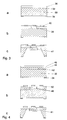
- Fig. 3a shows a first phase of the production of the silicon block by means of electrochemical etch stop.
- a p-type silicon substrate 30, e.g. a 4 inch wafer having a resistivity of 5 - 10 ⁇ cm, is used as a source material.
- a main surface of the substrate 30 a 200 nm deep n-implantation 32 is carried out.
- LPCVD Low Pressure Chemical Vapour Deposition
- the oxide/nitride layer is structured by photolithography and dry etching methods, whereby a structured oxide/ nitride layer 34 is obtained. On the opposite side, the oxide/nitride layer is removed, whereupon a silicon carbide layer 36 is applied.
- contact holes 38 reaching down to said n-implantation 32 are etched through this silicon carbide layer 36.
- a contact material e.g. aluminum
- a metal e.g. platinum or gold
- vapour deposition is applied by vapour deposition and structured such that the desired structure 40, e.g. a meander, is obtained.
- the substrate 30 is etched electrochemically in KOH (potassium hydroxide solution) or in TMAH. This will result in the structure shown in Fig. 3c.
- KOH potassium hydroxide solution
- TMAH TMAH
- the thin n-implantation 32 and the low etch stop voltage applied thereto are of importance.
- the remaining silicon block is, consequently, p-type (5-10 ⁇ cm, 5 ⁇ m), and the frame of the silicon carbide membrane is silicon free.
- the p-type silicon block is treated in the manner described hereinbefore so as to obtain the detection element consisting of a microporous silicon and the catalytically active noble metal contained therein.
- Fig. 4 shows an alternative method of producing the silicon block 10.
- the source material is again a p-type silicon substrate 30.
- a structured oxide/nitride layer is produced on the bottom side of the silicon substrate 30.
- the nitride layer is removed, and the oxide layer is structured by photolithography and dry etching methods so as to form an oxide etch stop 42.
- an LPCVD polysilicon layer is applied to the top side of the substrate 30.
- the oxide etch stop 42 could also be produced by implanting an oxide into the silicon substrate (SOI).
- a PECVD silicon carbide 46 is applied to the layer 44 by chemical vapour deposition.
- the silicon carbide layer 46 has again formed therein, e.g. by means of a dry etching method, contact holes 48 extending into in the vapour-deposited or bonded silicon layer 44.
- resistance structures 50 are applied to the silicon carbide layer 46 by vapour deposition.
- the substrate 30 is then etched anisotropically from the bottom side; during this etching process, the oxide 42 acts as an etch stop.
- the structure shown in Fig. 4c is obtained as a result of said etching process.
- the above-mentioned steps are carried out so as to produce from said silicon block 10 a porous silicon block in which a catalytically active noble metal is contained.
- the membrane 12 used as a carrier in the case of the present invention consists preferably of SiC, Si 3 N 4 , SiO 2 or thin silicon.
- the catalytically active noble metal is preferably palladium, platinum, iridium or a mixture of these materials.
- the material used as microporous material is preferably silicon, silicon dioxide or some other silicon compound.
- the heating and temperature detection means applied to the membrane may comprise thermoelectric couples in addition to the above-mentioned thin film resistors consisting preferably of platinum or gold, with and without adhesion layers like Ni, Cr, NiCr, Ti, etc.. To achieve a good bonding additional metal layers can be arranged on the metal layers used for the heating and temperature detecting elements.
- the present invention provides a catalytic gas sensor element by means of which less easily oxidized molecules can be detected, which consumes little power and which shows a high sensitivity as well as a speedy response.
- the present invention can be used for gas sensing for different purposes, e.g. in warning devices, and for the purpose of leakage detection, control of working areas, process control and gas analysis.
Landscapes
- Chemical & Material Sciences (AREA)
- Chemical Kinetics & Catalysis (AREA)
- Electrochemistry (AREA)
- Physics & Mathematics (AREA)
- Health & Medical Sciences (AREA)
- Life Sciences & Earth Sciences (AREA)
- Analytical Chemistry (AREA)
- Biochemistry (AREA)
- General Health & Medical Sciences (AREA)
- General Physics & Mathematics (AREA)
- Immunology (AREA)
- Pathology (AREA)
- Investigating Or Analyzing Materials By The Use Of Electric Means (AREA)
- Catalysts (AREA)
Description
- The present invention refers to a catalytic gas sensor element used for a qualitative and quantitative detection of gases.
- Catalytic gas sensors are known, which include noble metals with the aid of which potentially present gases are detected qualitatively and quantitatively. For this purpose, a catalyst, normally a noble metal, is applied to a carrier, e.g. a membrane. The other side of the carrier has arranged thereon heating and detection elements. The heating elements are used for the purpose of heating the catalyst to a specific temperature. If a gas is present in the atmosphere surrounding the noble metal, said gas will react with the catalyst, whereby an increase in temperature will be caused. This increase in temperature is then detected by means of a temperature detection element. If a resistor is used as a heating element, e.g. a thin film resistor applied to the carrier in the form of a meander, this resistor, whose resistivity changes as the temperature changes, can also be used as a temperature detection element.
- Catalytic gas sensors of the type described hereinbefore show little stability and high poisoning and ageing effects in addition to other disadvantages.
- EP-A-0446483 relates to a catalytic gas sensor comprising a diaphragm supported by a support structure of silicon. On a main surface of the diaphragm opposite to the support structure, a catalytically active layer is provided for detecting the presence of a gas. In addition, heating means are provided in order to warm up different portions of the active layer to different temperatures. Temperature sensing means are provided for sensing the temperature of the different portions.
- EP-A-0703449 relates to a catalytic calorimetric gas sensor including a sol-gel processed washcoat and sol-processed catalytically active metal particels deposited on the washcoat with high surface area and controlled porosity which increases the sensitivity, durability and reproducibility of the sensor. In accordance with this prior art sensor, a membrane having a low thermal conductivity is supported by a silicon frame on one main surface thereof. Temperature measuring layers are provided on the second surface of the membrane. The temperature measuring layers are covered by a passivation layer. On top of the temperature measuring layers catalytic layers are provided which are separated from the temperature measuring layers by the passivation layer.
- It is an object of the present invention to provide a method of producing a catalytic gas sensor element showing a high stability, little poisoning and ageing effects as well as a high sensitivity.
- This object is achieved by a method according to claim 1.
- It is a further object of the present invention to provide a catalytic gas sensor showing a high stability, little poisoning and ageing effects as well as a high sensitivity.
- This object is achieved by a catalytic gas sensor element according to
claim 10. - The detection element of the catalytic gas sensor according to the present invention which consists of a microporous material has preferably a large surface, and this results in high sensitivity and stability and little poisoning and ageing effects. It follows that less easily oxidized molecules, e.g. methane, can be detected. A carrier, to which the detection element is attached, is preferably a silicon free membrane, and, therefore, less heat is lost and power consumption is low. A catalytic gas sensor element according to the present invention can preferably be produced by means of micromachining techniques. The specific features resulting from this type of production are batch processing, easy arraying, a high sensitivity and a speedy response.
- In the following, preferred embodiments of the present invention will be explained in detail making reference to the drawings enclosed, in which:
- Fig. 1
- shows a perspective view of a catalytic gas sensor element according to the present invention;
- Fig. 2
- shows the representation of a measurement of methane by means of a catalytic gas sensor element according to the present invention;
- Fig. 3
- shows production steps of a first embodiment of a method according to the present invention used for producing a catalytic gas sensor element; and
- Fig. 4
- shows production steps of a second embodiment used for producing a catalytic gas sensor element according to the present invention.
- Fig. 1 shows a preferred embodiment of a catalytic gas sensor element according to the present invention, which is adapted to be produced by means of micromachining techniques. A
detection element 10 is attached to the bottom side of acarrier membrane 12. Thedetection element 10 of the preferred embodiment consists of a microporous p-type silicon block, the bottom side of which is impregnated with a catalytically active noble metal. Themembrane 12 of the preferred embodiment consists of silicon carbide. The bottom side of saidmembrane 12 has additionally attached theretoholding means - The top side of the
membrane 12 of the preferred embodiment has provided thereonmetallic resistance structures 18, which are used for heating thedetection element 10 as well as for temperature measurement. Themetallic structures 18 can be applied to themembrane 12 e.g. in the form of a meander. The resistance structures may, for example, only comprise one resistance film used as a heating element and also as a temperature detection element. Furthermore, the resistance structures may comprise two resistance films, one of said resistance films being used as a heating element and the other one as a temperature detection element. In addition, contact holes are arranged in themembrane 12, said contact holes being used for electrically connecting themicroporous silicon block 10 to thewafer frame membrane 12 by metallic structures on the upper side of the wafer. - In the following, the mode of operation of the above-described catalytic gas sensor element or pellistor will be described. The microporous block is heated to an elevated temperature (e.g. 200 - 600°C). A gas, which is to be detected, is adsorbed at the huge inner surface of the microporous silicon block; in the course of this process, a combustion reaction takes place. This reaction produces heat, and this has the effect that the temperature of the
detection element 10 rises. This rise in the temperature of thedetection element 10 is detected by detecting changes in the resistivity of theresistance structures 18 arranged on saidmembrane 12, said changes in the resistivity being caused by a temperature change. In this way, qualitative and quantitative detection of gases is possible. - In view of the fact that the porous silicon block has a large surface at which the reaction takes place - a property that results in high sensitivity, in high stability and little poisoning and ageing effects - less easily oxidized molecules can be detected. Fig. 2 shows the detection characteristics of two catalytic gas sensor elements according to the present invention including palladium as a catalytically active noble metal in the porous silicon block. Because silicon carbide is used for the membrane of the preferred embodiment little heat is lost and power consumption is low. A frame consisting of
silicon - If a burnable gas, such as CO, methane, alcohols, etc. is present in the air surrounding the
porous silicon block 10, this gas will be burnt by the catalytically active material - metal and insulator material - at the heatedporous silicon block 10. The resultant heat is correlated with the gas concentration. - The heated part is thermally isolated from a holder, e.g. the holding means 14 and 16. In accordance with the preferred embodiment, this is achieved by attaching the heated part, i.e. the
porous silicon block 10, to a thermally isolating membrane. The frame holding this membrane is either fixed to a header, or it is held by bonding wires, or it is secured in position in some other way known in the field of technology. The thermally isolating membrane can consist e.g. of SiC (silicon carbide), Si3N4, SiO2, thin Si or another material. Also slits can be provided in the membrane for further reduction of the heat conductivity. The thermal isolation of the heated part can also be achieved by holding said heated part by bonding wires, some other material, or by means of a micromachined chip. - The
porous silicon block 10 is produced making use of known methods of producing microporous silicon structures which make use of a hydrofluoric acid. The porous silicon block is then heated so as to stabilize it and so as to produce OH groups on the surface thereof. The stabilization of the silicon is done by oxidation of Si to SiOx. In this way, OH groups are obtained at the surface of the silicon. The surface treated in this way is impregnated by a precursor of a catalytically active noble metal so as to obtain in said porous silicon block a deposit of palladium with high dispersion. Further, other processes of depositing metals in the porous material are possible. The metal used as a catalytically active noble metal can e.g. be palladium, platinum, iridium or a mixture of these materials. A p-type silicon is preferably used as a microporous material because of the pore size after the formation of the porous layer. Microporous silicon having a pore size in the nanometer region has the lowest thermal conductivity and the highest transformation rates of CH4 into CO2 and H2O. Furthermore, palladium, for example, is able to penetrate porous silicon films up to depths of at least 10 µm. - The process for introducing palladium in a porous medium, such as porous silicon, is known and is described, for example in the article "Infrared Study of Oxidized and Reduced Palladium Loaded Zeolits" by M. Primet and Y. Ben Taarit in Journal of Physical Chemistry, 1977, 81, 1317.
- Making reference to Fig. 3 and 4, two methods of producing the
silicon block 10 will be explained hereinbelow by way of example. In accordance with the first embodiment, the silicon block is realized by electrochemical etch stop, whereas according to the second method the silicon block is realized by oxide etch stop. After the production of the silicon block the porous layer is formed and the impregnation is carried out. - Fig. 3a shows a first phase of the production of the silicon block by means of electrochemical etch stop. A p-
type silicon substrate 30, e.g. a 4 inch wafer having a resistivity of 5 - 10 Ωcm, is used as a source material. In a main surface of the substrate 30 a 200 nm deep n-implantation 32 is carried out. Subsequently, an LPCVD oxide and nitride layer (LPCVD = Low Pressure Chemical Vapour Deposition) is formed on the whole surface of thesubstrate 30. On the lower surface of thesubstrate 30, i.e. the surface which is located opposite the surface in which the n-implantation 32 has been carried out, the oxide/nitride layer is structured by photolithography and dry etching methods, whereby a structured oxide/nitride layer 34 is obtained. On the opposite side, the oxide/nitride layer is removed, whereupon asilicon carbide layer 36 is applied. - As can be seen in Fig. 3b, contact holes 38 reaching down to said n-
implantation 32 are etched through thissilicon carbide layer 36. Subsequently, a contact material, e.g. aluminum, is evaporated into said contact holes 38, whereby a contact will be established between the n-implantation and the wafer frame. Following this, a metal, e.g. platinum or gold, is applied by vapour deposition and structured such that the desiredstructure 40, e.g. a meander, is obtained. - Subsequently, the
substrate 30 is etched electrochemically in KOH (potassium hydroxide solution) or in TMAH. This will result in the structure shown in Fig. 3c. In connection with this etching, the thin n-implantation 32 and the low etch stop voltage applied thereto are of importance. The remaining silicon block is, consequently, p-type (5-10 Ωcm, 5 µm), and the frame of the silicon carbide membrane is silicon free. - Following this, the p-type silicon block is treated in the manner described hereinbefore so as to obtain the detection element consisting of a microporous silicon and the catalytically active noble metal contained therein.
- Fig. 4 shows an alternative method of producing the
silicon block 10. The source material is again a p-type silicon substrate 30. In correspondence with the previously described embodiment, a structured oxide/nitride layer is produced on the bottom side of thesilicon substrate 30. On the top side of thesubstrate 30, the nitride layer is removed, and the oxide layer is structured by photolithography and dry etching methods so as to form anoxide etch stop 42. Following this, an LPCVD polysilicon layer is applied to the top side of thesubstrate 30. Alternatively, it is also possible to apply a silicon wafer with a recess to the top side of thesubstrate 30 and to connect it thereto. Furthermore, the oxide etch stop 42 could also be produced by implanting an oxide into the silicon substrate (SOI). - In a subsequent step, a
PECVD silicon carbide 46 is applied to thelayer 44 by chemical vapour deposition. Thesilicon carbide layer 46 has again formed therein, e.g. by means of a dry etching method, contact holes 48 extending into in the vapour-deposited or bondedsilicon layer 44. Following this,resistance structures 50 are applied to thesilicon carbide layer 46 by vapour deposition. - The
substrate 30 is then etched anisotropically from the bottom side; during this etching process, theoxide 42 acts as an etch stop. The structure shown in Fig. 4c is obtained as a result of said etching process. When theoxide 42 has been removed, the above-mentioned steps are carried out so as to produce from said silicon block 10 a porous silicon block in which a catalytically active noble metal is contained. - The
membrane 12 used as a carrier in the case of the present invention consists preferably of SiC, Si3N4, SiO2 or thin silicon. The catalytically active noble metal is preferably palladium, platinum, iridium or a mixture of these materials. The material used as microporous material is preferably silicon, silicon dioxide or some other silicon compound. The heating and temperature detection means applied to the membrane may comprise thermoelectric couples in addition to the above-mentioned thin film resistors consisting preferably of platinum or gold, with and without adhesion layers like Ni, Cr, NiCr, Ti, etc.. To achieve a good bonding additional metal layers can be arranged on the metal layers used for the heating and temperature detecting elements. - It follows that the present invention provides a catalytic gas sensor element by means of which less easily oxidized molecules can be detected, which consumes little power and which shows a high sensitivity as well as a speedy response. The present invention can be used for gas sensing for different purposes, e.g. in warning devices, and for the purpose of leakage detection, control of working areas, process control and gas analysis.
Claims (17)
- A method of producing a catalytic gas sensor element, comprising the following steps:forming a mask layer (34) on a first main surface of a silicon substrate (30), the silicon substrate (30) being provided with an etch stop (32; 42) in a predetermined positional relation to a second main surface thereof;forming a thermally isolating layer (12; 36; 46) on the second main surface of said silicon substrate (30);forming a heating and temperature detecting means (18) on said thermally isolating layer (12; 36; 46);etching the silicon substrate (30) from said first surface thereof making use of said mask layer (34) and said etch stop (32; 42) in order to produce a carrier structure (16) and, separately therefrom, a silicon block (41) on said thermally isolating layer;treating the silicon block (41) so as to produce a block consisting of microporous silicon;heating the microporous silicon so as to produce OH groups on a surface thereof; andimpregnating the surface of the microporous silicon, on which said OH groups have been produced, with a noble metal precursor.
- A method according to claim 1, wherein contact holes (38; 48) are produced through said formed thermally isolating layer.
- A method according to claim 1 or 2, wherein said mask layer (34) is formed by an oxide and nitride layer.
- A method according to one of the claims 1 to 3, wherein said thermally isolating layer (12; 36; 46) is formed by a silicon carbide layer, a Si3N4 layer or a SiO2 layer.
- A method according to one of the claims 1 to 4, wherein said heating and temperature detecting means (18) is formed by resistance structures (40; 50).
- A method according to one of the claims 1 to 5, wherein the etching step comprises electrochemical etching of the silicon substrate (30), an implantation layer (32) being used for producing an etch stop.
- A method according to one of the claims 1 to 5, wherein the etching step comprises anisotropic etching of the silicon substrate (30), an oxide area (42) arranged in said substrate being used as an etch stop.
- A method according to one of the claims 1 to 7, wherein the porosity of the catalyst carrier material is produced by electrochemical etching of silicon in HF.
- A method according to one of the claims 1 to 8, wherein a palladium, a platinum or an iridium precursor is used as a noble metal precursor.
- An catalytic gas sensor comprising:a silicon carrier structure (14, 16);a thermally isolating membrane (12) arranged on said silicon carrier structure (14, 16);a heating and temperature detection means (18) arranged on said thermally isolating membrane (12) opposite to said silicon carrier structure (14, 16);a detection element (10) located on said thermally isolating membrane (12) opposite to said heating and temperature detection means (18) and spaced apart from said silicon carrier structure (14, 16), the detection element (10) consisting of a microporous silicon, a microporous silicon dioxide or a microporous silicon compound impregnated with a catalyst; whereinsaid silicon carrier structure and said detection element are formed of the same silicon substrate.
- A catalytic gas sensor according to claim 10, wherein the catalyst is a catalytically active noble metal.
- A catalytic gas sensor according to claim 10 or 11, wherein the microporous material consists of a p-type silicon.
- A catalytic gas sensor according to one of the claims 10 to 12, wherein the catalytically active noble metal is palladium, platinum or iridium.
- A catalytic gas sensor according to one of the claims 10 to 13, wherein said membrane (12) consists of SiC, Si3N4 or SiO2.
- A catalytic gas sensor according to one of the claims 10 to 14, wherein said heating and temperature detection means (18) comprises a resistance structure used as a heating element and also as a temperature detection element.
- A catalytic gas sensor according to one of the claims 10 to 15, wherein said heating and temperature detection means (18) comprises two resistance structures, one of said resistance structures being used as a heating element, whereas the other one is used as a temperature detection element.
- A catalytic gas sensor according to one of the claims 10 to 16, wherein said heating and temperature detection means comprises a thermoelectric couple.
Priority Applications (2)
| Application Number | Priority Date | Filing Date | Title |
|---|---|---|---|
| EP19960111696 EP0819935B1 (en) | 1996-07-19 | 1996-07-19 | A catalytic gas sensor element |
| DE1996601930 DE69601930T2 (en) | 1996-07-19 | 1996-07-19 | Catalytic gas sensor element |
Applications Claiming Priority (1)
| Application Number | Priority Date | Filing Date | Title |
|---|---|---|---|
| EP19960111696 EP0819935B1 (en) | 1996-07-19 | 1996-07-19 | A catalytic gas sensor element |
Publications (2)
| Publication Number | Publication Date |
|---|---|
| EP0819935A1 EP0819935A1 (en) | 1998-01-21 |
| EP0819935B1 true EP0819935B1 (en) | 1999-03-31 |
Family
ID=8223012
Family Applications (1)
| Application Number | Title | Priority Date | Filing Date |
|---|---|---|---|
| EP19960111696 Expired - Lifetime EP0819935B1 (en) | 1996-07-19 | 1996-07-19 | A catalytic gas sensor element |
Country Status (2)
| Country | Link |
|---|---|
| EP (1) | EP0819935B1 (en) |
| DE (1) | DE69601930T2 (en) |
Families Citing this family (9)
| Publication number | Priority date | Publication date | Assignee | Title |
|---|---|---|---|---|
| EP1088785A1 (en) * | 1999-09-10 | 2001-04-04 | Ecole Polytechnique Federale De Lausanne | Fabrication process for a three- dimensional suspended microstructure, an integrated microstructure obtained by this process and an adjustable integrated micro-optical element |
| AU2002355079C1 (en) | 2001-07-16 | 2008-03-06 | Sensor Tech, Inc. | Sensor device and method for qualitative and quantitative analysis of gas phase substances |
| AU2007234632B2 (en) * | 2001-07-16 | 2010-02-18 | Sensor Tech, Inc. | Sensor device and method for qualitative and quantitative analysis of gas phase substances |
| GR1004040B (en) * | 2001-07-31 | 2002-10-31 | Method for the fabrication of suspended porous silicon microstructures and application in gas sensors | |
| EP1306349B1 (en) * | 2001-10-24 | 2007-03-14 | Robert Bosch Gmbh | Method of manufacture of an array of membrane sensors and array of membrane sensors |
| CN104316578B (en) * | 2014-10-31 | 2018-03-02 | 中国矿业大学 | A kind of MEMS methane transducers and its application and preparation method |
| DE102016203239B4 (en) | 2016-02-29 | 2025-02-27 | Robert Bosch Gmbh | MEMS sensor with a heating device on a membrane and corresponding manufacturing process |
| CN108275649B (en) * | 2018-03-16 | 2023-06-23 | 苏州芯镁信电子科技有限公司 | MEMS combustible gas sensor and processing method thereof |
| DE102023212471A1 (en) * | 2023-12-11 | 2025-06-12 | Robert Bosch Gesellschaft mit beschränkter Haftung | Microelectromechanical gas sensor and method for producing a microelectromechanical gas sensor |
Family Cites Families (4)
| Publication number | Priority date | Publication date | Assignee | Title |
|---|---|---|---|---|
| CA1164944A (en) * | 1980-01-02 | 1984-04-03 | International Gas Detectors Limited | Gas sensor elements and methods of manufacturing them |
| DE4008150A1 (en) * | 1990-03-14 | 1991-09-19 | Fraunhofer Ges Forschung | CATALYTIC GAS SENSOR |
| US5421958A (en) * | 1993-06-07 | 1995-06-06 | The United States Of America As Represented By The Administrator Of The United States National Aeronautics And Space Administration | Selective formation of porous silicon |
| US5707148A (en) * | 1994-09-23 | 1998-01-13 | Ford Global Technologies, Inc. | Catalytic calorimetric gas sensor |
-
1996
- 1996-07-19 EP EP19960111696 patent/EP0819935B1/en not_active Expired - Lifetime
- 1996-07-19 DE DE1996601930 patent/DE69601930T2/en not_active Expired - Fee Related
Also Published As
| Publication number | Publication date |
|---|---|
| DE69601930D1 (en) | 1999-05-06 |
| EP0819935A1 (en) | 1998-01-21 |
| DE69601930T2 (en) | 1999-10-07 |
Similar Documents
| Publication | Publication Date | Title |
|---|---|---|
| US5451371A (en) | High-sensitivity, silicon-based, microcalorimetric gas sensor | |
| US5813764A (en) | Catalytic differential calorimetric gas sensor | |
| CA1286212C (en) | Semiconductor gas sensor having thermally isolated site | |
| US7104113B2 (en) | Miniaturized multi-gas and vapor sensor devices and associated methods of fabrication | |
| US7238941B2 (en) | Pyrolyzed-parylene based sensors and method of manufacture | |
| US20040161949A1 (en) | Semiconductor and device nanotechnology and methods for their manufacture | |
| US6171378B1 (en) | Chemical preconcentrator | |
| US4343768A (en) | Gas detector | |
| US9580305B2 (en) | Single silicon wafer micromachined thermal conduction sensor | |
| US6326229B1 (en) | Process for manufacturing integrated semiconductor devices comprising a chemoresistive gas microsensor | |
| Zanini et al. | Fabrication and properties of a Si-based high-sensitivity microcalorimetric gas sensor | |
| JP2005505758A (en) | Micromachining type thermal conductivity sensor with porous cover | |
| JPH09119912A (en) | Semiconductor sensor device and method for forming the same | |
| US5834627A (en) | Calorimetric gas sensor | |
| EP0819935A1 (en) | A catalytic gas sensor element | |
| CN108313972B (en) | A hydrogen sensor and its processing method and use | |
| US20050212531A1 (en) | Fluid sensor and methods | |
| US5820922A (en) | Method for localized deposition of noble metal catalysts with control of morphology | |
| JP3828973B2 (en) | Sensor and manufacturing method thereof | |
| JP2002513930A (en) | Hydrogen sensor | |
| JPH08505234A (en) | Humidity sensor | |
| Cavicchi et al. | Microhotplate gas sensor arrays | |
| KR100489303B1 (en) | Diamond film gas sensor and method of making the same | |
| KR0178155B1 (en) | Method for manufacturing micro-heating unit of gas sensor | |
| EP1160567A2 (en) | Sensor and method for measuring gas concentrations |
Legal Events
| Date | Code | Title | Description |
|---|---|---|---|
| PUAI | Public reference made under article 153(3) epc to a published international application that has entered the european phase |
Free format text: ORIGINAL CODE: 0009012 |
|
| 17P | Request for examination filed |
Effective date: 19970808 |
|
| AK | Designated contracting states |
Kind code of ref document: A1 Designated state(s): DE FR GB NL |
|
| AX | Request for extension of the european patent |
Free format text: LT;LV;SI |
|
| 17Q | First examination report despatched |
Effective date: 19980508 |
|
| GRAG | Despatch of communication of intention to grant |
Free format text: ORIGINAL CODE: EPIDOS AGRA |
|
| GRAG | Despatch of communication of intention to grant |
Free format text: ORIGINAL CODE: EPIDOS AGRA |
|
| GRAH | Despatch of communication of intention to grant a patent |
Free format text: ORIGINAL CODE: EPIDOS IGRA |
|
| AKX | Designation fees paid |
Free format text: DE FR GB NL |
|
| RBV | Designated contracting states (corrected) |
Designated state(s): DE FR GB NL |
|
| GRAH | Despatch of communication of intention to grant a patent |
Free format text: ORIGINAL CODE: EPIDOS IGRA |
|
| GRAA | (expected) grant |
Free format text: ORIGINAL CODE: 0009210 |
|
| AK | Designated contracting states |
Kind code of ref document: B1 Designated state(s): DE FR GB NL |
|
| RAP2 | Party data changed (patent owner data changed or rights of a patent transferred) |
Owner name: SCHLUMBERGER INDUSTRIES Owner name: DAIMLERCHRYSLER AG Owner name: FRAUNHOFER-GESELLSCHAFT ZUR FOERDERUNG DER ANGEWAN |
|
| REF | Corresponds to: |
Ref document number: 69601930 Country of ref document: DE Date of ref document: 19990506 |
|
| NLT2 | Nl: modifications (of names), taken from the european patent patent bulletin |
Owner name: FRAUNHOFER-GESELLSCHAFT ZUR FOERDERUNG DER ANGEWAN |
|
| ET | Fr: translation filed | ||
| NLXE | Nl: other communications concerning ep-patents (part 3 heading xe) |
Free format text: PAT. BUL. 06/99 PAGE 805: CORR.: DAIMLER CHRYSLER AG |
|
| PLBE | No opposition filed within time limit |
Free format text: ORIGINAL CODE: 0009261 |
|
| STAA | Information on the status of an ep patent application or granted ep patent |
Free format text: STATUS: NO OPPOSITION FILED WITHIN TIME LIMIT |
|
| 26N | No opposition filed | ||
| PGFP | Annual fee paid to national office [announced via postgrant information from national office to epo] |
Ref country code: GB Payment date: 20010706 Year of fee payment: 6 |
|
| PGFP | Annual fee paid to national office [announced via postgrant information from national office to epo] |
Ref country code: FR Payment date: 20010723 Year of fee payment: 6 |
|
| PGFP | Annual fee paid to national office [announced via postgrant information from national office to epo] |
Ref country code: NL Payment date: 20010727 Year of fee payment: 6 |
|
| PGFP | Annual fee paid to national office [announced via postgrant information from national office to epo] |
Ref country code: DE Payment date: 20010926 Year of fee payment: 6 |
|
| REG | Reference to a national code |
Ref country code: GB Ref legal event code: IF02 |
|
| PG25 | Lapsed in a contracting state [announced via postgrant information from national office to epo] |
Ref country code: GB Free format text: LAPSE BECAUSE OF NON-PAYMENT OF DUE FEES Effective date: 20020719 |
|
| REG | Reference to a national code |
Ref country code: FR Ref legal event code: GC |
|
| PG25 | Lapsed in a contracting state [announced via postgrant information from national office to epo] |
Ref country code: NL Free format text: LAPSE BECAUSE OF NON-PAYMENT OF DUE FEES Effective date: 20030201 Ref country code: DE Free format text: LAPSE BECAUSE OF NON-PAYMENT OF DUE FEES Effective date: 20030201 |
|
| GBPC | Gb: european patent ceased through non-payment of renewal fee |
Effective date: 20020719 |
|
| PG25 | Lapsed in a contracting state [announced via postgrant information from national office to epo] |
Ref country code: FR Free format text: LAPSE BECAUSE OF NON-PAYMENT OF DUE FEES Effective date: 20030331 |
|
| NLV4 | Nl: lapsed or anulled due to non-payment of the annual fee |
Effective date: 20030201 |
|
| REG | Reference to a national code |
Ref country code: FR Ref legal event code: ST |
|
| REG | Reference to a national code |
Ref country code: FR Ref legal event code: DG |