EP0819846B1 - Fuel injection apparatus having cylinder screw for mounting fuel injector on engine - Google Patents
Fuel injection apparatus having cylinder screw for mounting fuel injector on engine Download PDFInfo
- Publication number
- EP0819846B1 EP0819846B1 EP97112301A EP97112301A EP0819846B1 EP 0819846 B1 EP0819846 B1 EP 0819846B1 EP 97112301 A EP97112301 A EP 97112301A EP 97112301 A EP97112301 A EP 97112301A EP 0819846 B1 EP0819846 B1 EP 0819846B1
- Authority
- EP
- European Patent Office
- Prior art keywords
- injector
- cylinder head
- mounting
- engagement part
- thread
- Prior art date
- Legal status (The legal status is an assumption and is not a legal conclusion. Google has not performed a legal analysis and makes no representation as to the accuracy of the status listed.)
- Expired - Lifetime
Links
Images



Classifications
-
- F—MECHANICAL ENGINEERING; LIGHTING; HEATING; WEAPONS; BLASTING
- F02—COMBUSTION ENGINES; HOT-GAS OR COMBUSTION-PRODUCT ENGINE PLANTS
- F02M—SUPPLYING COMBUSTION ENGINES IN GENERAL WITH COMBUSTIBLE MIXTURES OR CONSTITUENTS THEREOF
- F02M61/00—Fuel-injectors not provided for in groups F02M39/00 - F02M57/00 or F02M67/00
- F02M61/16—Details not provided for in, or of interest apart from, the apparatus of groups F02M61/02 - F02M61/14
-
- F—MECHANICAL ENGINEERING; LIGHTING; HEATING; WEAPONS; BLASTING
- F02—COMBUSTION ENGINES; HOT-GAS OR COMBUSTION-PRODUCT ENGINE PLANTS
- F02M—SUPPLYING COMBUSTION ENGINES IN GENERAL WITH COMBUSTIBLE MIXTURES OR CONSTITUENTS THEREOF
- F02M61/00—Fuel-injectors not provided for in groups F02M39/00 - F02M57/00 or F02M67/00
- F02M61/14—Arrangements of injectors with respect to engines; Mounting of injectors
-
- F—MECHANICAL ENGINEERING; LIGHTING; HEATING; WEAPONS; BLASTING
- F02—COMBUSTION ENGINES; HOT-GAS OR COMBUSTION-PRODUCT ENGINE PLANTS
- F02B—INTERNAL-COMBUSTION PISTON ENGINES; COMBUSTION ENGINES IN GENERAL
- F02B3/00—Engines characterised by air compression and subsequent fuel addition
- F02B3/06—Engines characterised by air compression and subsequent fuel addition with compression ignition
Definitions
- the present invention relates to a fuel injection apparatus in which a fuel injector is mounted on an internal combustion engine through a cylinder screw.
- soot and the similar substances produced in the combustion are likely to accumulate between the nozzle part and the cylinder head and stick thereat.
- the injector must be shaken or pried to be detached from the cylinder head by using certain tools after unthreading the cylinder screw from the cylinder head, resulting in the difficulty in detaching work.
- the force applied to the injector deforms members constituting the magnetic circuit of the injector or varies the biasing force of a spring, resulting in changes in injection characteristics of the injector, i.e., fuel injection timing and fuel injection quantity. Thus, it becomes impossible to reuse the injector which has been detached once.
- the position of the injector is likely to displace in the turning direction even if the injector is held gripped by the tool.
- a cylinder screw is threaded into the cylinder head until it abuts the retaining nut for pressing the injector to the cylinder head.
- the injector is pressed to the cylinder head at an end position of the thread engagement part between the housing and the retaining nut which is opposite to the injector attaching direction.
- the distance between the position where the retaining nut is engaged with the cylinder head and the position where the retaining nut is pressed by the cylinder screw becomes long, increasing the deformation of the retaining nut by the tightening force of the cylinder screw.
- the increase in the deformation of the retaining nut increases the deformation of the injector constituting members, particularly, the deformation of members located within the axial length of the retaining nut.
- this attachment structure is applied to an electromagnetically-controlled injector, the air gap between a movable core and a stationary core may be shortened, a sliding clearance of movable parts may be reduced or fixing condition between members may be weakened.
- the deformation in the injector will cause changes in injection quantity and injection timing of the injector, making it difficult to provide the injection characteristics as designed.
- an injector has a connecting member or a retaining nut which connects a nozzle body and a housing.
- a cylindrical mounting member abuts the connecting member at the lowermost part of a thread engagement part between the connecting member and the housing.
- a pressing member presses the mounting member to a cylinder head. This shortens the axial length of the injector held between the cylinder head and the mounting member and reduces deformation of injector constituting members at the time of attaching the injector to the cylinder head.
- the air gap between a movable core and a stationary core will be restricted from being shortened and the sliding clearance of a movable member will be restricted from being reduced, keeping the injection characteristics of the injector.
- a cylindrical mounting member is used to mount or attach the injector to an engine.
- the injector has two engagement parts at which the mounting member abuts.
- the mounting member not only presses a first engagement part in a direction of attachment of the injector to a cylinder head but also presses a second engagement part in a direction opposite to the injector mounting direction. This enables detachment of the injector from the cylinder head with ease by only loosening a thread engagement between the mounting member and the engine, turning the mounting member further until its abutment with the second engagement part and finally turning the mounting member and the injector integrally, even when soot and similar substances remain sticking strongly between the injector and the cylinder head.
- the injector and the cylinder head will be damaged less.
- the injector is therefore reusable after detachment because the injector maintains its injection characteristics.
- the first engagement part and the second engagement part of the injector are provided to reside in the cylinder head under the condition the injector is attached to the cylinder head.
- the distance between the soot-sticking part and the second engagement part becomes short, the deformation of the injector will be reduced even when the injector is detached with its second engagement part being pressed with a large force under the circumstance that the soot and the similar substances attach between the injector and the cylinder head strongly.
- the injector has a rotation restricting member.
- the rotation restricting member is engaged with a cylinder head at the time of attaching the injector to the cylinder head or connecting a fuel pipe to the injector. This restricts the injector from turning in a rotating direction to simplify mounting work. As the rotational position of the injector is thus maintained, the fuel injection direction of the injector can be set as designed.
- a thread tightening force of a connecting member applied at the time of connecting a fuel pipe is restricted from exerting on a side of the injector opposite to the connecting member.
- injector constituting members at the side opposite to the connecting member will not be deformed by the tightening force of the connecting member.
- a twisting force is applied only between the rotation restricting member and a part which is thread-engaged with the connecting member at the time of connecting the fuel pipe.
- an electromagnetically controlled fuel injector 10 of a fuel injection apparatus is mounted on a cylinder head 1 of an engine to directly inject fuel into a combustion chamber of each cylinder.
- the injector 10 is placed in position by a stopper 40 with respect to its rotating or circumferential direction.
- the injector 10 is attached by fitting into a mounting hole 2 of the cylinder head 1 by threading a cylinder screw 60 which functions as a cylindrical mounting member into the cylinder head 1.
- a housing 11 and a nozzle body 20 of the injector 10 are coupled to each other by a retaining nut 22 with a spacer 21 being sandwiched therebetween.
- the retaining nut 22 is formed with a reduced diameter part 22a at its lowermost end at the side of an injection hole 24.
- the reduced diameter part 22a is engaged with the nozzle body 20.
- the housing 11 and the nozzle body 20 are coupled by a thread engagement between a female thread 22b formed on the inner peripheral wall of the upper cylindrical wall of the retaining nut 22 and a male thread 11a formed on the outer peripheral wall of the housing 11.
- An annular flange 22c which functions as a first engagement part and protrudes radially outwardly is formed around the outer periphery of the retaining nut 22 at a position between the reduced diameter part 22a and the female thread 22b.
- the housing 11 is formed with a tapered surface 11b which functions as a second engagement part and abuts the cylinder screw 60 when the cylinder screw 60 moved upward.
- the tapered surface 11b is formed so that the outer diameter of the housing 11 reduces in the downward direction in Fig. 1, that is, as it comes closer to the side of injection hole 24 of the nozzle body 20.
- a needle valve 23 is housed reciprocally movably in the nozzle body 20. Fuel is injected through the injection hole 24 formed in the bottom end of the nozzle body 20 at the time the needle valve 23 is lifted from a valve seat 23 formed on the inside wall of the nozzle body 20.
- the injection hole 24 is formed to have a predetermined angle relative to the longitudinal axis of the injector 10.
- the injection hole 24 is formed to have the predetermined angle against the longitudinal axis of the injector 10 for the purpose that fuel is stratified and combusted in the combustion chamber of an in-cylinder direct injection type engine in which fuel is directly injected into the engine cylinder, that is, the fuel is injected to form a rich mixture around a spark plug (not shown) and a lean mixture in the remaining space with respect to an air-fuel mixture distribution.
- the mixture distribution in the cylinder should be optimumly controlled for the stratified combustion, it is required to provide injection hole 24 with the predetermined angle against the longitudinal axis of the injector 10 and to determine the position of the injector 10 with respect to the rotating direction of the injector 10 so that the fuel spray from the injection hole 24 may be directed in the predetermined direction in the cylinder.
- a movable core 30 is fixed by laser welding or the like to the needle valve 23 at its lower end.
- a stationary core 31 is placed inside the housing 11 to face the movable core 30 in the axial or longitudinal direction and has an air gap 36 against the stationary core 30.
- the stationary core 31 is fixed by laser welding or the like to the housing 11 at the top end of the housing 11.
- a spring 32 biases the movable core 30 to normally close the injection hole 24 by the needle valve 23. The biasing force of the spring 32 is adjusted by adjusting the axial position of an adjusting pipe 33 when the injector 10 is assembled.
- An exciting coil 34 is wound around a spool 35 and is disposed radially between the housing 11 and the stationary core 31.
- the needle valve 23 When the coil 34 is kept deenergized, the needle valve 23 is biased by the spring 32 to seat on the valve seat 20a and close the injection hole 24 so than no fuel is injected from the injection hole 24.
- the movable core 30 When the coil 34 is energized, the movable core 30 is attracted toward the stationary core 31 against the biasing force of the spring 32 by the attraction force in the air gap 36 caused by the magnetic force generated by the coil 34.
- the needle valve 23 lifts with the movable core 30 at this time and leaves from the valve seat 20a so that fuel is injected from the injection hole 24.
- a connector 41 is resin-molded with the housing 11 and the stationary core 31.
- a power receiving pin 42 housed in the connector 41 is electrically connected to the coil 34 to supply electric power to the coil 34.
- a pipe connector 51 connected to a fuel pipe 50 is pressed to the fuel inlet opening of the stationary core 31 by a retaining nut 52.
- the fuel flowing from the pipe 50 is subjected to filtering out foreign matters by a filter 43 and introduced into the injector 10.
- the stopper 40 is formed annularly and fixed to the stationary core 31 by welding, brazing or the like.
- the stopper 40 may be formed integrally with the stationary core 31.
- a protrusion 40a extending radially is formed on the stopper 40 at a predetermined circumferential position of the stopper 40 so that it may be fitted into a positioning groove 3a extending longitudinally in the cylinder head 1.
- a protrusion 3 is formed on an uppermost part of the cylinder head 1 to be higher than the part where the mounting hole 2 for the injector 10 is drilled.
- the positioning groove 3a is formed on the side wall of the protrusion 3.
- the positioning groove 3a extends in parallel with the longitudinal direction of the injector 10, that is, in the injector mounting direction. The position of the injector 10 in the rotating direction is determined by inserting the protrusion 40a in the positioning groove 3a, thus determining the direction of fuel injection from the injection hole 24.
- the cylinder screw 60 is shaped cylindrically.
- a male thread 60a formed on its outer periphery wall is thread-engaged with a female thread 2a formed on the inner peripheral wall of the mounting hole 2.
- a tapered surface 60b is formed on the cylinder screw 60 at the top axial end opposite to the side of injection hole 24 in such a manner that its inner diameter increases in the upward direction in Fig. 1, that is, as it is farther from the injection hole 24.
- the cylinder screw 60 presses the flange 22c in the longitudinal direction of injector 10, leaving a spacing between the tapered surfaces 11b and 60b.
- the tapered surface 60b presses the tapered surface 11b in a direction opposite to the injector mounting direction leaving a space between the bottom axial end of the cylinder screw 60 and the annular flange 22c. That is, the cylinder screw 60 abuts the flange 22c or the tapered surface 60b at its both axial ends which are opposite in position in the axial direction of the injector 10.
- a washer 61 is placed on a stepped part 2b of the mounting hole 2.
- the injector 10 is attached to and detached from the cylinder head in the following manner.
- the cylinder screw 60 is capable of abutting the injector 10 at both ends in the direction of attaching the injector 10 to the cylinder head 1 and in the direction of detaching the injector 10 from the cylinder head 1.
- the injector 10 can be attached to and detached from the cylinder head 1 by the use of one cylinder screw 60.
- the injector 10 can be lifted axially in the detaching direction, the injector 10 can be detached from the cylinder head 1 with ease without damaging the injector 10 and the cylinder head 1 even under the condition that the soot or the similar substance is sticking between the nozzle part of the injector 10 and the cylinder head 1. Therefore, the injection characteristics of the injector 10 thus detached can be maintained so that the injector 10 may be reused.
- the thread-engagement part between the retaining nut 22 and the housing 11 is made shorter than in the first embodiment.
- An annular flange 11c which protrudes radially outwardly and functions as the second engagement part is provided on the outer periphery of the housing 11.
- the flange 11c is near the end of the thread-engagement part and opposite to the injection hole 24.
- the flange 11c as the second engagement part is located radially at substantially the same elevation as the bottom end of the stationary core 31 (air gap between the cores 30 and 31) so that it is located more closely to the injection hole 24 than the tapered surface 11b as the second engagement part of the first embodiment.
- the male thread 60a is provided around the outer peripheral wall of the cylinder screw 60 for thread-engagement with the female thread 2a of the mounting hole 2.
- the cylinder screw 60 is formed with a small diameter part 60c at the lowermost part which is close to the injection hole 24.
- the inner diameter of small diameter part 60c is smaller than the flanges 22c and 11c.
- the axial length of the small diameter part 60c is shorter than the axial distance between the flanges 11c and 22c.
- the flange 11c as the second engagement part is provided at a position close to the injection hole 24 as described above, the flange 11c as well as the flange 22c are located within the cylinder head 1 under the condition the injector 10 is attached to the cylinder head 1 as shown in Fig. 2. Accordingly, even in the case that a large force is applied from the cylinder screw 60 to the flange 11c to detach the injector 10 from the cylinder head 1 against sticking of soot and similar substance between the nozzle part of the injector 10 and the cylinder head 1, the deformation which may be caused in the injector 10 will be reduced to less than in the first embodiment owing to the shortened distance between the soot-stuck part and the flange.
- the third embodiment shown in Figs. 3 and 4 is similar to the first embodiment shown in Fig. 1.
- the housing 11 and the nozzle body 20 are coupled in the injector 10 as follows.
- the nozzle body 20 is inserted turnably within the retaining nut 22 and the housing 11.
- An axial bottom end surface 20b of the nozzle body 20 is held in abutment with an upper end surface 22d of the retaining nut 22, preferably through an annular ring (not shown).
- the retaining nut 22 is thread-engaged with the housing 11 as in the first embodiment.
- the stopper 40 which functions as a rotation restricting member is shaped annularly and fixed to the stationary core 30 by welding, brazing or the like.
- the stopper 40 may be made integrally with the stationary core 30.
- the protrusion 40a which is inserted into the positioning groove 3a as a recess part is provided at a predetermined circumferential position.
- Two cuts 40b are formed on the stopper 40 at both sides which crosses perpendicularly to the direction of the protrusion 40a of the stopper 40 so that the injector 10 may be held with ease by gripping the cuts 40b.
- tilting of the injector 10 may be prevented by gripping the cuts 40b of the stopper 40 by an appropriate tool.
- the protrusion 40a is engaged in the groove 3a and restricted from turning in the direction of tightening the injector 10, it is only required that the injector 10 be held in position by the tool to the extent that the injector 10 does not tilt.
- injector mounting operation can be simplified. While tightening the cylinder screw 60, the protrusion 40a is restricted by the positioning groove 3a from turning in the rotating direction.
- the tightening force of the cylinder screw 60 applied in the rotating direction does not exert directly onto the injector 10.
- a thin annular ring (not shown) being inserted as a sliding member in the abutment part between the cylinder screw 60 and the retaining nut 22, the cylinder screw 60 will slide on the thin annular ring even when the cylinder screw 60 is tightened under the abutment with the retaining nut 22. As a result, the rotating force of the cylinder screw 60 will not exert directly onto the retaining nut 22, that is, onto the injector 10.
- the injector 10 when the injector 10 is attached to the cylinder head 1 by the cylinder screw 60, the thread-engaging force in the rotating direction will not exert directly onto the abutment part between the cylinder screw 60 and the retaining nut 22 and the abutment part between the protrusion 4a and the positioning groove 3a. Therefore, the twisting force, which will exert on the magnetic circuit constituting members of the injector 10, the adjusting pipe 33 as an injection quantity adjusting member for adjusting the biasing force of the spring biasing the valve member and the like all being housed between the above two abutment parts, will be minimized.
- the injection characteristics of the injector 10, that is, injection timing and injection quantity of the injector 10, can be maintained without being not altered by changes in the air gap between the cores 30 and 31 and biasing force on the valve member, by degradation of sliding characteristics of the movable members, or degradation of fixing strength at the fixed parts between members in the injector 10.
- the fuel pipe 50 is connected to the injector 10 after mounting the injector 10 on the cylinder head 1.
- the pipe connector 51 is fixed to the end of the fuel pipe 50.
- the pipe connector 51 and the injector 10 are connected by thread-engaging the retaining nut 52 with the injector 10. Because the retaining nut 52 and the injector 10 are in direct thread-engagement with each other, the tightening force in the rotation direction of the retaining nut 52 exerts directly onto the injector 10 as the thread-engagement proceeds.
- the tightening force of the retaining nut 52 in the rotation direction does not exert on the injector 10 which is mostly at the injection hole side from the stopper 40. Therefore, the twisting force does not exert on the magnetic circuit constituting members, adjusting pipe 33 and the like which are housed within the injector 10 existing at the injection hole side from the stopper 40.
- the injection characteristics of the injector 10, that is, injection timing and injection quantity of the injector 10 can be maintained without being not altered by changes in the air gap and biasing force on the valve member, by degradation of sliding characteristics of the movable members, or degradation of fixing strength at the fixed parts between members in the injector 10.
- the protrusion 40a is restricted by the recess 3a from turning in the direction opposite to the direction of rotation at the time of mounting the injector 10 and connecting the fuel pipe 50 so that the injector 10 is also restricted from turning as well.
- the twisting force does not exert on the magnetic circuit constituting members, adjusting pipe 33 and the like which are housed within the injector 10.
- the injection characteristics of the injector 10, that is, injection timing and injection quantity of the injector 10 can be maintained without being not altered by changes in the air gap and biasing force on the valve member, by degradation of sliding characteristics of the movable members, or degradation of fixing strength at the fixed parts between members in the injector 10.
- the injector 10 thus detached can be reused.
- the protrusion 40a is engaged with the positioning groove 3a in both rotating directions of the injector 10 in this embodiment, the protrusion 40a may be engaged with the groove 3a only in the tightening direction of the cylinder screw 60 and the retaining nut 52.
- the injector 10 is restricted from rotating by providing the protrusion 40a on the injector 10 and the recess 3a in the cylinder head 1 in this embodiment, the recess 3a and the protrusion 40a may be provided in the injector 10 and on the cylinder head 1, respectively.
- the injector 10 is detached from the cylinder head 1 by loosening the thread-engagement between the cylinder screw 60 and the cylinder head 1 and thereby pressing the housing 11 upwardly in this embodiment, it may be so modified that only the cylinder screw 60 is detached from the cylinder head 1 at the time of loosening the thread-engagement between the cylinder screw 60 and the cylinder head 1.
- the injector 10 may be detached from the cylinder head 1 by gripping and pulling out the injector 10 by an appropriate tool.
- the injector 10 is attached to the cylinder head 1 by the tightening force of the cylinder screw 60 for the thread-engagement with the cylinder head 1, it is also possible to mount the injector 10 in the cylinder head 1 by fixedly engaging a cylindrical member fitted on the injector 10 with the injector 10 and pressing the cylindrical member in the mounting direction to the cylinder head 1 by the use of an appropriate tool.
- the fourth embodiment shown in Fig. 5 is also similar to the first embodiment shown in Fig. 1.
- the flange 22c abuts the cylinder screw 60 at an axial lower end 60d of the thread-engagement part between the housing 11 and the retaining nut 22.
- This end 60d is on the side in the mounting direction of the injector 10 and is opposite to an axial upper end 22e of the thread-engagement part in the injector mounting direction. This position is distanced from the air gap 36 provided between the movable core 30 and the stationary core 31 in the injector mounting direction.
- the amount of deformation in the thickness of the flange 22c increases with the thickness.
- the magnetic circuit constituting members in the injector 10 such as the stationary core 31 and movable core 30 may deform resulting in shortening of the air gap 36.
- the biasing force of the spring 32 which biases the movable core 32 may be changed also due to the deformation of the members. It may also occur that the sliding characteristics of the movable part in the injector 10 degrade or the fixing strength between the members is weakened.
- the injector performance expected at the time of manufacturing can not be provided. According to this embodiment, however, because the axial length to which the tightening force of the cylinder screw 60 is applied is shortened, the deformation of the members in the injector 10 is reduced as shown in Fig. 6 so that changes in the fuel injection characteristics may be reduced. Further, because the position where the tightening force of the cylinder screw 60 exerts is on the side of the air gap 36 in the injector mounting direction, the shortening of the air gap 36 is reduced to a possible minimum.
- the cylinder screw 60 and the mounting hole 2 have no threads on the respective outer peripheral wall and the inner peripheral wall.
- the injector 10 is not fixedly engaged in the cylinder head 1 but held reciprocably movably.
- the cylinder screw 60 abuts the flange 22c of the retaining nut 22, at the axial end 60d located at the side of the thread-engagement part between the housing 11 and the retaining nut 22 in the injector mounting direction than the side of the same part in the direction opposite to the injector mounting direction, to press the flange 22c toward the washer 61 in the same manner as in the foregoing embodiments.
- a pressing member 80 has a pair of arms 81 which abut the top surface of the end 60e of the cylinder screw 60.
- the housing 11 is formed with a pair of recesses on radial sides of its outer peripheral wall.
- the arms 81 abut those recesses from both sides to determine the position of the injector 10 in its rotating direction.
- the arms 81 are formed with respective protrusions 82 at the connecting part therebetween.
- the protrusions 82 fit in recesses 4 formed on the surface of the cylinder head 1.
- the injector 10 fitted in the cylinder screw 60 is inserted into the mounting hole 2.
- the protrusion 82 is then fitted in the recess 4 while restricting the rotational position of the injector 10 by the arms 81 of the pressing member 80.
- a bolt 83 is threaded into the cylinder head 1 so that the arms 81, with its protrusion 82 functioning as a fulcrum, presses the cylinder screw 60 in the injector mounting direction thus attaching the injector 10 to the cylinder head 1.
- the injector 10 can be detached from the cylinder head 1, once the bolt 83 is loosened and disengage the pressing member 80 from the injector 10.
Landscapes
- Engineering & Computer Science (AREA)
- Chemical & Material Sciences (AREA)
- Combustion & Propulsion (AREA)
- Mechanical Engineering (AREA)
- General Engineering & Computer Science (AREA)
- Fuel-Injection Apparatus (AREA)
Description
- The present invention relates to a fuel injection apparatus in which a fuel injector is mounted on an internal combustion engine through a cylinder screw.
- It is known from US 1 948 557 A to use a cylinder screw for mounting a fuel injector on a cylinder head of a direct injection type engine in which fuel is injected directly into an engine cylinder. The cylinder screw is fitted around the outer periphery of the injector. The cylinder screw is threaded into the cylinder head to press the injector to the cylinder head.
- As the nozzle part of the injector faces a combustion chamber according to the injector in the above direct injection type engine, however, soot and the similar substances produced in the combustion are likely to accumulate between the nozzle part and the cylinder head and stick thereat. When the soot and the similar substances remain sticking strongly, the injector must be shaken or pried to be detached from the cylinder head by using certain tools after unthreading the cylinder screw from the cylinder head, resulting in the difficulty in detaching work.
- Further, it may occur that the force applied to the injector deforms members constituting the magnetic circuit of the injector or varies the biasing force of a spring, resulting in changes in injection characteristics of the injector, i.e., fuel injection timing and fuel injection quantity. Thus, it becomes impossible to reuse the injector which has been detached once.
- It is also known by the publication ("DIESEL FUEL INJECTION", page 159, FIG. 4.108(C), published on June 15, 1988 by SANKAIDO) to mount an injector on a cylinder head without turning the injector. This injector may be attached by holding a flange by the cylinder head and a retaining nut, and by the retaining nut or the like a fuel pipe may be attached to the injector having been attached to the cylinder head. As a large turning force exerts on the injector at this moment, the injector must be gripped firmly by a certain tool to hold the injector in position to the turning direction for such an attaching work. This will complicate the injector mounting work.
- Further, as the large turning force is applied to the injector for a thread engagement between the retaining nut and the injector at the time of connecting the fuel pipe to the injector, the position of the injector is likely to displace in the turning direction even if the injector is held gripped by the tool.
- Still further, a cylinder screw is threaded into the cylinder head until it abuts the retaining nut for pressing the injector to the cylinder head. The injector is pressed to the cylinder head at an end position of the thread engagement part between the housing and the retaining nut which is opposite to the injector attaching direction. According to this attachment structure, the distance between the position where the retaining nut is engaged with the cylinder head and the position where the retaining nut is pressed by the cylinder screw becomes long, increasing the deformation of the retaining nut by the tightening force of the cylinder screw. The increase in the deformation of the retaining nut increases the deformation of the injector constituting members, particularly, the deformation of members located within the axial length of the retaining nut. Therefore, if this attachment structure is applied to an electromagnetically-controlled injector, the air gap between a movable core and a stationary core may be shortened, a sliding clearance of movable parts may be reduced or fixing condition between members may be weakened. The deformation in the injector will cause changes in injection quantity and injection timing of the injector, making it difficult to provide the injection characteristics as designed.
- It is an object of the present invention to provide an electromagnetically controlled fuel injection apparatus and engine cylinder head assembly, which does not alter injection characteristics of an injector which can occur when attaching the fuel injection to a cylinder head of an engine.
- According to the present invention, an injector has a connecting member or a retaining nut which connects a nozzle body and a housing. A cylindrical mounting member abuts the connecting member at the lowermost part of a thread engagement part between the connecting member and the housing. A pressing member presses the mounting member to a cylinder head. This shortens the axial length of the injector held between the cylinder head and the mounting member and reduces deformation of injector constituting members at the time of attaching the injector to the cylinder head. Thus, the air gap between a movable core and a stationary core will be restricted from being shortened and the sliding clearance of a movable member will be restricted from being reduced, keeping the injection characteristics of the injector.
- Preferably, a cylindrical mounting member is used to mount or attach the injector to an engine. The injector has two engagement parts at which the mounting member abuts. The mounting member not only presses a first engagement part in a direction of attachment of the injector to a cylinder head but also presses a second engagement part in a direction opposite to the injector mounting direction. This enables detachment of the injector from the cylinder head with ease by only loosening a thread engagement between the mounting member and the engine, turning the mounting member further until its abutment with the second engagement part and finally turning the mounting member and the injector integrally, even when soot and similar substances remain sticking strongly between the injector and the cylinder head. Further, as the force applied to the injector at the time of detaching the injector from the cylinder head exerts in the axial direction of the injector, the injector and the cylinder head will be damaged less. The injector is therefore reusable after detachment because the injector maintains its injection characteristics.
- Preferably, the first engagement part and the second engagement part of the injector are provided to reside in the cylinder head under the condition the injector is attached to the cylinder head. As the distance between the soot-sticking part and the second engagement part becomes short, the deformation of the injector will be reduced even when the injector is detached with its second engagement part being pressed with a large force under the circumstance that the soot and the similar substances attach between the injector and the cylinder head strongly. As a result, there will occur in the injector no substantial deformation of magnetic circuit constituting members nor substantial change in biasing force of a spring. This makes it possible to maintain the injection characteristics of the injector and to reuse the same.
- Preferably, the injector has a rotation restricting member. The rotation restricting member is engaged with a cylinder head at the time of attaching the injector to the cylinder head or connecting a fuel pipe to the injector. This restricts the injector from turning in a rotating direction to simplify mounting work. As the rotational position of the injector is thus maintained, the fuel injection direction of the injector can be set as designed.
- Preferably, a thread tightening force of a connecting member applied at the time of connecting a fuel pipe is restricted from exerting on a side of the injector opposite to the connecting member. Thus, injector constituting members at the side opposite to the connecting member will not be deformed by the tightening force of the connecting member.
- Preferably, a twisting force is applied only between the rotation restricting member and a part which is thread-engaged with the connecting member at the time of connecting the fuel pipe. Thus, as the magnetic circuit constituting members and injection quantity metering members of the injector will not be deformed, the injection characteristics of the injector will not be altered.
- Other objects, features and advantages of the present invention will be made more apparent from the following detailed description with reference to the accompanying drawings, in which:
- Fig. 1 is a longitudinal sectional view of a fuel injection apparatus according to the first embodiment of the present invention;
- Fig. 2 is a longitudinal sectional view of a fuel injection apparatus according to the second embodiment of the present invention;
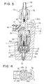
- Fig. 3 is a longitudinal sectional view of a fuel injection apparatus according to the third embodiment of the present invention;
- Fig. 4 is a transverse sectional view of the third embodiment including a stopper;
- Fig. 5 is a longitudinal sectional view of a fuel injection apparatus according to the fourth embodiment of the present invention;
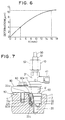
- Fig. 6 is a characteristic chart illustrating a difference between deformations in the fourth embodiment and a comparative example; and
- Fig. 7 is a side view of a fuel injection apparatus according to the fifth embodiment of the present invention.
- The present invention will be described in detail with reference to various embodiments in which the same or similar reference numerals are used to denote the same or similar parts throughout the embodiments.
- As shown in Fig. 1, an electromagnetically controlled
fuel injector 10 of a fuel injection apparatus is mounted on acylinder head 1 of an engine to directly inject fuel into a combustion chamber of each cylinder. Theinjector 10 is placed in position by astopper 40 with respect to its rotating or circumferential direction. Theinjector 10 is attached by fitting into amounting hole 2 of thecylinder head 1 by threading acylinder screw 60 which functions as a cylindrical mounting member into thecylinder head 1. - A
housing 11 and anozzle body 20 of theinjector 10 are coupled to each other by aretaining nut 22 with aspacer 21 being sandwiched therebetween. Theretaining nut 22 is formed with a reduceddiameter part 22a at its lowermost end at the side of aninjection hole 24. The reduceddiameter part 22a is engaged with thenozzle body 20. Thehousing 11 and thenozzle body 20 are coupled by a thread engagement between afemale thread 22b formed on the inner peripheral wall of the upper cylindrical wall of the retainingnut 22 and amale thread 11a formed on the outer peripheral wall of thehousing 11. Anannular flange 22c which functions as a first engagement part and protrudes radially outwardly is formed around the outer periphery of the retainingnut 22 at a position between the reduceddiameter part 22a and thefemale thread 22b. Thehousing 11 is formed with atapered surface 11b which functions as a second engagement part and abuts thecylinder screw 60 when thecylinder screw 60 moved upward. Thetapered surface 11b is formed so that the outer diameter of thehousing 11 reduces in the downward direction in Fig. 1, that is, as it comes closer to the side ofinjection hole 24 of thenozzle body 20. - A
needle valve 23 is housed reciprocally movably in thenozzle body 20. Fuel is injected through theinjection hole 24 formed in the bottom end of thenozzle body 20 at the time theneedle valve 23 is lifted from avalve seat 23 formed on the inside wall of thenozzle body 20. Theinjection hole 24 is formed to have a predetermined angle relative to the longitudinal axis of theinjector 10. Theinjection hole 24 is formed to have the predetermined angle against the longitudinal axis of theinjector 10 for the purpose that fuel is stratified and combusted in the combustion chamber of an in-cylinder direct injection type engine in which fuel is directly injected into the engine cylinder, that is, the fuel is injected to form a rich mixture around a spark plug (not shown) and a lean mixture in the remaining space with respect to an air-fuel mixture distribution. Because the mixture distribution in the cylinder should be optimumly controlled for the stratified combustion, it is required to provideinjection hole 24 with the predetermined angle against the longitudinal axis of theinjector 10 and to determine the position of theinjector 10 with respect to the rotating direction of theinjector 10 so that the fuel spray from theinjection hole 24 may be directed in the predetermined direction in the cylinder. - A
movable core 30 is fixed by laser welding or the like to theneedle valve 23 at its lower end. Astationary core 31 is placed inside thehousing 11 to face themovable core 30 in the axial or longitudinal direction and has anair gap 36 against thestationary core 30. Thestationary core 31 is fixed by laser welding or the like to thehousing 11 at the top end of thehousing 11. Aspring 32 biases themovable core 30 to normally close theinjection hole 24 by theneedle valve 23. The biasing force of thespring 32 is adjusted by adjusting the axial position of an adjustingpipe 33 when theinjector 10 is assembled. Anexciting coil 34 is wound around aspool 35 and is disposed radially between thehousing 11 and thestationary core 31. - When the
coil 34 is kept deenergized, theneedle valve 23 is biased by thespring 32 to seat on thevalve seat 20a and close theinjection hole 24 so than no fuel is injected from theinjection hole 24. When thecoil 34 is energized, themovable core 30 is attracted toward thestationary core 31 against the biasing force of thespring 32 by the attraction force in theair gap 36 caused by the magnetic force generated by thecoil 34. Theneedle valve 23 lifts with themovable core 30 at this time and leaves from thevalve seat 20a so that fuel is injected from theinjection hole 24. - A
connector 41 is resin-molded with thehousing 11 and thestationary core 31. Apower receiving pin 42 housed in theconnector 41 is electrically connected to thecoil 34 to supply electric power to thecoil 34. - A
pipe connector 51 connected to afuel pipe 50 is pressed to the fuel inlet opening of thestationary core 31 by a retainingnut 52. The fuel flowing from thepipe 50 is subjected to filtering out foreign matters by afilter 43 and introduced into theinjector 10. - The
stopper 40 is formed annularly and fixed to thestationary core 31 by welding, brazing or the like. Thestopper 40 may be formed integrally with thestationary core 31. Aprotrusion 40a extending radially is formed on thestopper 40 at a predetermined circumferential position of thestopper 40 so that it may be fitted into apositioning groove 3a extending longitudinally in thecylinder head 1. - A
protrusion 3 is formed on an uppermost part of thecylinder head 1 to be higher than the part where the mountinghole 2 for theinjector 10 is drilled. Thepositioning groove 3a is formed on the side wall of theprotrusion 3. Thepositioning groove 3a extends in parallel with the longitudinal direction of theinjector 10, that is, in the injector mounting direction. The position of theinjector 10 in the rotating direction is determined by inserting theprotrusion 40a in thepositioning groove 3a, thus determining the direction of fuel injection from theinjection hole 24. - The
cylinder screw 60 is shaped cylindrically. Amale thread 60a formed on its outer periphery wall is thread-engaged with afemale thread 2a formed on the inner peripheral wall of the mountinghole 2. Atapered surface 60b is formed on thecylinder screw 60 at the top axial end opposite to the side ofinjection hole 24 in such a manner that its inner diameter increases in the upward direction in Fig. 1, that is, as it is farther from theinjection hole 24. Under the condition that thecylinder screw 60 is fitted around the outer periphery of theinjector 10 before theinjector 10 is attached to thecylinder head 1, thecylinder screw 60 is held axially movably between thetapered surface 11b and theflange 22c. - When thread-engaged with the
cylinder head 1 for mounting theinjector 10 in the mountinghole 2, thecylinder screw 60 presses theflange 22c in the longitudinal direction ofinjector 10, leaving a spacing between thetapered surfaces cylinder head 1 is loosened for detaching theinjector 10 from the mountinghole 2, on the other hand, thetapered surface 60b presses thetapered surface 11b in a direction opposite to the injector mounting direction leaving a space between the bottom axial end of thecylinder screw 60 and theannular flange 22c. That is, thecylinder screw 60 abuts theflange 22c or thetapered surface 60b at its both axial ends which are opposite in position in the axial direction of theinjector 10. - A
washer 61 is placed on a steppedpart 2b of the mountinghole 2. When thecylinder screw 60 is thread-engaged with thecylinder head 1, theflange 22c of the retainingnut 22 is pressed onto thewasher 61 by the tightening force of thecylinder screw 60. - The
injector 10 is attached to and detached from the cylinder head in the following manner. - 1. Attachment of injector 10:
- (1) The
washer 61 is placed on the steppedpart 2b of the mountinghole 2 of thecylinder head 1. Theinjector 10 with thecylinder screw 60 being movably fitted therearound is inserted in the longitudinal direction into the mountinghole 2 while guiding theprotrusion 40a of thestopper 40 by thepositioning groove 3a. When thecylinder screw 60 has not been tightened to thecylinder head 1, theflange 22c of the retainingnut 22 does not abut thewasher 61. - (2) When the
cylinder screw 60 is turned in the direction of thread-engagement with thecylinder head 1, thecylinder screw 60 abuts and presses down the top surface of theflange 22c. Thus, theinjector 10 is inserted into the mountinghole 2 together with thecylinder screw 60 until theflange 22c abuts thewasher 61. Theinjector 10 moves only in the longitudinal direction because turning is restricted by the engagement between theprotrusion 40a and thepositioning groove 3a. - (3) When the
cylinder screw 60 is tightened further, the end of the bottom end of thecylinder screw 60 tightly abuts theflange 22c, pressing theinjector 10 to thecylinder head 1 firmly as shown in Fig. 1.
- (1) The
- 2. Detachment of injector 10:
- (1) As the thread-engagement is loosened from the condition shown in Fig. 1 by turning the
cylinder screw 60 in a direction reverse to the direction of thread-engagement with thecylinder head 1, only thecylinder screw 60 is moved upward releasing the abutment of its bottom surface from the top surface of theflange 22c. Thetapered surface 60b of thecylinder screw 60 then comes into abutment with thetapered surface 11b of thehousing 11. - (2) When the
cylinder screw 60 is turned further in the direction to loosen the thread-engagement, thecylinder screw 60 now presses thetapered surface 11b of thehousing 11 upward. Thus, theinjector 10 is lifted upward in Fig. 1, that is, in a direction theinjector 10 is detached from thecylinder head 1, while keeping the taperedsurface 60b in abutment with thetapered surface 11b. - (3) When the
cylinder screw 60 is turned further in the direction of loosening the thread-engagement, the thread-engagement between thecylinder head 1 and thecylinder screw 60 is released so that theinjector 10 may be detached from thecylinder head 1.
- (1) As the thread-engagement is loosened from the condition shown in Fig. 1 by turning the
- According to the above first embodiment, the
cylinder screw 60 is capable of abutting theinjector 10 at both ends in the direction of attaching theinjector 10 to thecylinder head 1 and in the direction of detaching theinjector 10 from thecylinder head 1. Theinjector 10 can be attached to and detached from thecylinder head 1 by the use of onecylinder screw 60. - As the
injector 10 can be lifted axially in the detaching direction, theinjector 10 can be detached from thecylinder head 1 with ease without damaging theinjector 10 and thecylinder head 1 even under the condition that the soot or the similar substance is sticking between the nozzle part of theinjector 10 and thecylinder head 1. Therefore, the injection characteristics of theinjector 10 thus detached can be maintained so that theinjector 10 may be reused. - In the second embodiment shown in Fig. 2, the thread-engagement part between the retaining
nut 22 and thehousing 11 is made shorter than in the first embodiment. Anannular flange 11c which protrudes radially outwardly and functions as the second engagement part is provided on the outer periphery of thehousing 11. Theflange 11c is near the end of the thread-engagement part and opposite to theinjection hole 24. Theflange 11c as the second engagement part is located radially at substantially the same elevation as the bottom end of the stationary core 31 (air gap between thecores 30 and 31) so that it is located more closely to theinjection hole 24 than the taperedsurface 11b as the second engagement part of the first embodiment. - The
male thread 60a is provided around the outer peripheral wall of thecylinder screw 60 for thread-engagement with thefemale thread 2a of the mountinghole 2. Thecylinder screw 60 is formed with asmall diameter part 60c at the lowermost part which is close to theinjection hole 24. The inner diameter ofsmall diameter part 60c is smaller than theflanges small diameter part 60c is shorter than the axial distance between theflanges cylinder screw 60 is fitted axially movably between theflanges injector 10 is not mounted on thecylinder head 1. - According to the second embodiment, because the
flange 11c as the second engagement part is provided at a position close to theinjection hole 24 as described above, theflange 11c as well as theflange 22c are located within thecylinder head 1 under the condition theinjector 10 is attached to thecylinder head 1 as shown in Fig. 2. Accordingly, even in the case that a large force is applied from thecylinder screw 60 to theflange 11c to detach theinjector 10 from thecylinder head 1 against sticking of soot and similar substance between the nozzle part of theinjector 10 and thecylinder head 1, the deformation which may be caused in theinjector 10 will be reduced to less than in the first embodiment owing to the shortened distance between the soot-stuck part and the flange. As most of the members which constitute a magnetic circuit of theinjector 10 as well as the adjustingpipe 33 which determines the biasing force of thespring 32 are not located between the soot-stuck part and theflange 11, the air gap between thecores spring 32 will change less. As a result, the injection characteristics of theinjector 10 will not be altered much and hence theinjector 10 may be reused after detached. - The third embodiment shown in Figs. 3 and 4 is similar to the first embodiment shown in Fig. 1. In this embodiment, the
housing 11 and thenozzle body 20 are coupled in theinjector 10 as follows. Thenozzle body 20 is inserted turnably within the retainingnut 22 and thehousing 11. An axialbottom end surface 20b of thenozzle body 20 is held in abutment with anupper end surface 22d of the retainingnut 22, preferably through an annular ring (not shown). The retainingnut 22 is thread-engaged with thehousing 11 as in the first embodiment. - As shown in Fig. 4, the
stopper 40 which functions as a rotation restricting member is shaped annularly and fixed to thestationary core 30 by welding, brazing or the like. Thestopper 40 may be made integrally with thestationary core 30. Theprotrusion 40a which is inserted into thepositioning groove 3a as a recess part is provided at a predetermined circumferential position. Twocuts 40b are formed on thestopper 40 at both sides which crosses perpendicularly to the direction of theprotrusion 40a of thestopper 40 so that theinjector 10 may be held with ease by gripping thecuts 40b. - When the
cylinder screw 60 is tightened, tilting of theinjector 10 may be prevented by gripping thecuts 40b of thestopper 40 by an appropriate tool. In this instance, because theprotrusion 40a is engaged in thegroove 3a and restricted from turning in the direction of tightening theinjector 10, it is only required that theinjector 10 be held in position by the tool to the extent that theinjector 10 does not tilt. Thus, injector mounting operation can be simplified. While tightening thecylinder screw 60, theprotrusion 40a is restricted by thepositioning groove 3a from turning in the rotating direction. - As the
cylinder screw 60 is thread-engaged with thecylinder head 1 and theinjector 10 is pressed to thecylinder head 1 by the tightening force of thecylinder screw 60, the tightening force of thecylinder screw 60 applied in the rotating direction does not exert directly onto theinjector 10. With a thin annular ring (not shown) being inserted as a sliding member in the abutment part between thecylinder screw 60 and the retainingnut 22, thecylinder screw 60 will slide on the thin annular ring even when thecylinder screw 60 is tightened under the abutment with the retainingnut 22. As a result, the rotating force of thecylinder screw 60 will not exert directly onto the retainingnut 22, that is, onto theinjector 10. - As described above, when the
injector 10 is attached to thecylinder head 1 by thecylinder screw 60, the thread-engaging force in the rotating direction will not exert directly onto the abutment part between thecylinder screw 60 and the retainingnut 22 and the abutment part between the protrusion 4a and thepositioning groove 3a. Therefore, the twisting force, which will exert on the magnetic circuit constituting members of theinjector 10, the adjustingpipe 33 as an injection quantity adjusting member for adjusting the biasing force of the spring biasing the valve member and the like all being housed between the above two abutment parts, will be minimized. Thus, the injection characteristics of theinjector 10, that is, injection timing and injection quantity of theinjector 10, can be maintained without being not altered by changes in the air gap between thecores injector 10. - The
fuel pipe 50 is connected to theinjector 10 after mounting theinjector 10 on thecylinder head 1. Thepipe connector 51 is fixed to the end of thefuel pipe 50. Thepipe connector 51 and theinjector 10 are connected by thread-engaging the retainingnut 52 with theinjector 10. Because the retainingnut 52 and theinjector 10 are in direct thread-engagement with each other, the tightening force in the rotation direction of the retainingnut 52 exerts directly onto theinjector 10 as the thread-engagement proceeds. - However, with the
protrusion 40a being restricted from turning by thepositioning groove 3a, the tightening force of the retainingnut 52 in the rotation direction does not exert on theinjector 10 which is mostly at the injection hole side from thestopper 40. Therefore, the twisting force does not exert on the magnetic circuit constituting members, adjustingpipe 33 and the like which are housed within theinjector 10 existing at the injection hole side from thestopper 40. Thus, the injection characteristics of theinjector 10, that is, injection timing and injection quantity of theinjector 10, can be maintained without being not altered by changes in the air gap and biasing force on the valve member, by degradation of sliding characteristics of the movable members, or degradation of fixing strength at the fixed parts between members in theinjector 10. - In each case of detaching the
fuel pipe 50 from theinjector 10 and detaching theinjector 10 from thecylinder head 1, theprotrusion 40a is restricted by therecess 3a from turning in the direction opposite to the direction of rotation at the time of mounting theinjector 10 and connecting thefuel pipe 50 so that theinjector 10 is also restricted from turning as well. Thus, detaching work will be attained with ease as in the mounting work. - As in the case of mounting the
injector 10 and connecting thefuel pipe 50, the twisting force does not exert on the magnetic circuit constituting members, adjustingpipe 33 and the like which are housed within theinjector 10. Thus, the injection characteristics of theinjector 10, that is, injection timing and injection quantity of theinjector 10, can be maintained without being not altered by changes in the air gap and biasing force on the valve member, by degradation of sliding characteristics of the movable members, or degradation of fixing strength at the fixed parts between members in theinjector 10. As a result, theinjector 10 thus detached can be reused. - Although the
protrusion 40a is engaged with thepositioning groove 3a in both rotating directions of theinjector 10 in this embodiment, theprotrusion 40a may be engaged with thegroove 3a only in the tightening direction of thecylinder screw 60 and the retainingnut 52. - Further, although the
injector 10 is restricted from rotating by providing theprotrusion 40a on theinjector 10 and therecess 3a in thecylinder head 1 in this embodiment, therecess 3a and theprotrusion 40a may be provided in theinjector 10 and on thecylinder head 1, respectively. - Still further, the
injector 10 is detached from thecylinder head 1 by loosening the thread-engagement between thecylinder screw 60 and thecylinder head 1 and thereby pressing thehousing 11 upwardly in this embodiment, it may be so modified that only thecylinder screw 60 is detached from thecylinder head 1 at the time of loosening the thread-engagement between thecylinder screw 60 and thecylinder head 1. In this instance, theinjector 10 may be detached from thecylinder head 1 by gripping and pulling out theinjector 10 by an appropriate tool. - Moreover, although the
injector 10 is attached to thecylinder head 1 by the tightening force of thecylinder screw 60 for the thread-engagement with thecylinder head 1, it is also possible to mount theinjector 10 in thecylinder head 1 by fixedly engaging a cylindrical member fitted on theinjector 10 with theinjector 10 and pressing the cylindrical member in the mounting direction to thecylinder head 1 by the use of an appropriate tool. - The fourth embodiment shown in Fig. 5 is also similar to the first embodiment shown in Fig. 1. In this embodiment, the
flange 22c abuts thecylinder screw 60 at an axial lower end 60d of the thread-engagement part between thehousing 11 and the retainingnut 22. This end 60d is on the side in the mounting direction of theinjector 10 and is opposite to an axialupper end 22e of the thread-engagement part in the injector mounting direction. This position is distanced from theair gap 36 provided between themovable core 30 and thestationary core 31 in the injector mounting direction. - The deformation which may occur in the
injector 10 by the tightening force of thecylinder screw 60 will become larger as the axial length to which the tightening force is applied becomes longer. Assuming a comparative example (axial length is 16 mm) in which the retainingnut 22 has the substantially the same outer diameter up to its end which is opposite in the injector mounting direction and thecylinder screw 60 abuts this end of the retainingnut 22 located oppositely in the injector mounting direction, the axial length to which the tightening force is applied is much longer than in the present embodiment in which the axial length is 4 mm. As shown in Fig. 6 in which the amount of deformation of the flange relative to the thickness X of the flange under the tightening force of 1500 kg is illustrated, the amount of deformation in the thickness of theflange 22c increases with the thickness. As the deformation in the injector increases, the magnetic circuit constituting members in theinjector 10 such as thestationary core 31 andmovable core 30 may deform resulting in shortening of theair gap 36. Further, the biasing force of thespring 32 which biases themovable core 32 may be changed also due to the deformation of the members. It may also occur that the sliding characteristics of the movable part in theinjector 10 degrade or the fixing strength between the members is weakened. - If the fuel injection characteristics of the
injector 10, that is, the fuel injection quantity and fuel injection timing of theinjector 10, change due to deformation in the injector constituting members at the time of attaching the injector, the injector performance expected at the time of manufacturing can not be provided. According to this embodiment, however, because the axial length to which the tightening force of thecylinder screw 60 is applied is shortened, the deformation of the members in theinjector 10 is reduced as shown in Fig. 6 so that changes in the fuel injection characteristics may be reduced. Further, because the position where the tightening force of thecylinder screw 60 exerts is on the side of theair gap 36 in the injector mounting direction, the shortening of theair gap 36 is reduced to a possible minimum. - In the fifth embodiment shown in Fig. 7, the
cylinder screw 60 and the mountinghole 2 have no threads on the respective outer peripheral wall and the inner peripheral wall. Under the condition that theinjector 10 fitted with thecylinder screw 60 is mounted in the mountinghole 2, theinjector 10 is not fixedly engaged in thecylinder head 1 but held reciprocably movably. Thecylinder screw 60 abuts theflange 22c of the retainingnut 22, at the axial end 60d located at the side of the thread-engagement part between thehousing 11 and the retainingnut 22 in the injector mounting direction than the side of the same part in the direction opposite to the injector mounting direction, to press theflange 22c toward thewasher 61 in the same manner as in the foregoing embodiments. A pressingmember 80 has a pair ofarms 81 which abut the top surface of theend 60e of thecylinder screw 60. Thehousing 11 is formed with a pair of recesses on radial sides of its outer peripheral wall. Thearms 81 abut those recesses from both sides to determine the position of theinjector 10 in its rotating direction. Thearms 81 are formed withrespective protrusions 82 at the connecting part therebetween. Theprotrusions 82 fit inrecesses 4 formed on the surface of thecylinder head 1. - The
injector 10 fitted in thecylinder screw 60 is inserted into the mountinghole 2. Theprotrusion 82 is then fitted in therecess 4 while restricting the rotational position of theinjector 10 by thearms 81 of the pressingmember 80. Finally, abolt 83 is threaded into thecylinder head 1 so that thearms 81, with itsprotrusion 82 functioning as a fulcrum, presses thecylinder screw 60 in the injector mounting direction thus attaching theinjector 10 to thecylinder head 1. - The
injector 10 can be detached from thecylinder head 1, once thebolt 83 is loosened and disengage the pressingmember 80 from theinjector 10. - According to this embodiment, no thread is necessitated on the mounting
hole 2 which is machined in correspondence with the end shape of theinjector 10. Therefore, machining the cylinder head is simplified.
Claims (13)
- A fuel injection apparatus and engine cylinder head assembly, the fuel injection apparatus, injecting fuel into the engine when mounted in a mounting hole (2) on the cylinder head (1), the assembly comprising:an injector (10) having a nozzle body (20) provided with an injection hole (24) at an end thereof and a housing (11) located oppositely to the injection hole (24) of the nozzle body (20) ;a retaining member (22) having a first end (22a) at the side of the injection hole (24) and a second end (22e), engaged with the housing (11) to retain the nozzle body (20) to the housing (11);a mounting member (60) fitted around the injector (10) and abutting axially the retaining member (22) at an end (60d) of an engagement part between the retaining member (22) and the housing (11), the end (60d) of the engagement part being located within the mounting hole (2); anda pressing member (2a, 60a, 80, 83) pressing the mounting member (60) in a direction of mounting the injector (10) thereby to press the retaining member (22) to a bottom of the mounting hole (2) and mount the injector (10) to the cylinder head (1), the retaining member (22) includes a flange (22c) extending radially outwardly and having a surface which is abutted by the mounting member (60) at a side opposite to the injection hole (24), characterised in that the injector is an electromagnetically controlled injector (10) and in that the end (60d) of the engagement part of the mounting member (60) is located closer to the injection hole (24) than the second end (22e) of the retaining member (22).
- The assembly according to claim 1, wherein:the pressing member (2a, 80, 83) includes a thread (2a, 60a) between the mounting member (60) and the cylinder head (1).
- The assembly according to claim 1, wherein:the pressing member (2a, 80, 83) includes an abutting member (80, 83) abutting the mounting member (60) at a location outside of the cylinder head (1) and a member (83) pressing the abutting member (80) in the direction of mounting the injector (10) thereby to mount the injector (10) to the cylinder head (1).
- The assembly according to any of claims claim 1 to 3, wherein
the injector (10) has a first engagement part (22c) and a second engagement part (11b, 11c) located axially oppositely; and
the mounting member (60) is fitted around an outer periphery of the injector (10) for attaching the injector (10) to the cylinder head (1) through a thread-engagement with the cylinder head (1), wherein the mounting member (60) is constructed to abut and press the first engagement part (22c) in a direction the injector (10) is attached to the cylinder head (1) through the thread-engagement with the cylinder head (1), and wherein the mounting member (60) is constructed to abut and press the second engagement part (11b, 11c) in an opposite direction when the thread-engagement with the cylinder head (1) is loosened to detach the injector (10) from the cylinder head (1). - The assembly according to claim 5, wherein
the first engagement part (22c) and the second engagement part (11c) are located axially within the mounting hole (2) of the cylinder head (1) under the condition the injector (10) is attached to the cylinder head (1). - The assembly according to claim 5 or 6, wherein
the injector (10) is an electromagnetic type including a movable core (30) and a stationary core (31) with an air gap (36) therebetween; and
the second engagement part (11c) is located at substantially the same elevation as the air gap (36) at radially outside the air gap (36). - The assembly according to any one of claims 5 through 6, wherein
the mounting member (60) is fitted around the injector (10) axially and circumferentially movably between the first engagement part (22c) and the second engagement part (11b, 11c). - The assembly according to claim 7, wherein
the second engagement part (11b) is formed with a tapered surface; and
the mounting member (60) is formed with a tapered surface which faces the tapered surface of the second engagement part (11b). - The assembly according to any of the preceding claims, wherein
the injector (10) has a rotation restricting member (40) engageable with the cylinder head (1) to restrict a rotation in at least one rotating direction; and
the mounting member (60) is for attaching the injector (10) to the cylinder head (1) axially while keeping the rotation restricting member (40a) in engagement with the cylinder head (1). - The assembly according to claim 9, wherein
the rotation restricting member (40) has a protrusion (40a) engageable with a recess (3a) provided in the cylinder head (1) to restrict the rotation in the one rotating direction. - The assembly according to claim 9 or 10, further comprising
a fuel pipe (50); and
a connecting member (52) thread-engageable with the injector (10) at an end of the injector (10) for connecting the fuel pipe (50) to the injector (10), the connecting member (52) being disabled by the rotation restricting member (40) to turn the injector (10) when threaded along the injector (10). - The assembly according to claim 11, wherein
the injector (10) includes a thread-engageable part for a thread-engagement with the connecting member (52), a magnetic circuit constituting member (30, 31) and an injection quantity metering member (32, 33); and the rotation restricting member (40) is positioned between the thread-engageable part and at least one of the magnetic circuit constituting member (30, 31) and the injection quantity metering member (32, 33). - The assembly according to any one of claims 9 through 12, wherein
the mounting member (60) has a cylinder screw fitted around the injector (10) and threadable into the cylinder head (1), the cylinder screw (60) being constructed to press the injector (10) to the cylinder head (1) when threaded into the cylinder head (1) to mount the injector (10) in the cylinder head (1).
Applications Claiming Priority (6)
| Application Number | Priority Date | Filing Date | Title |
|---|---|---|---|
| JP189213/96 | 1996-07-18 | ||
| JP18921296A JPH1030527A (en) | 1996-07-18 | 1996-07-18 | Fuel injection device |
| JP18921396A JPH1030528A (en) | 1996-07-18 | 1996-07-18 | Fuel injection device |
| JP189212/96 | 1996-07-18 | ||
| JP190537/96 | 1996-07-19 | ||
| JP19053796A JPH1037829A (en) | 1996-07-19 | 1996-07-19 | Fuel injection device |
Publications (2)
| Publication Number | Publication Date |
|---|---|
| EP0819846A1 EP0819846A1 (en) | 1998-01-21 |
| EP0819846B1 true EP0819846B1 (en) | 2006-03-15 |
Family
ID=27326146
Family Applications (1)
| Application Number | Title | Priority Date | Filing Date |
|---|---|---|---|
| EP97112301A Expired - Lifetime EP0819846B1 (en) | 1996-07-18 | 1997-07-17 | Fuel injection apparatus having cylinder screw for mounting fuel injector on engine |
Country Status (4)
| Country | Link |
|---|---|
| US (1) | US5943995A (en) |
| EP (1) | EP0819846B1 (en) |
| KR (1) | KR100301383B1 (en) |
| DE (1) | DE69735451T2 (en) |
Families Citing this family (18)
| Publication number | Priority date | Publication date | Assignee | Title |
|---|---|---|---|---|
| US6325049B1 (en) * | 1999-06-23 | 2001-12-04 | Siemens Automotive Corporation | Fuel injector with orientation feature for orienting injector with respect to the manifold or head |
| DE19954065A1 (en) * | 1999-11-10 | 2001-05-23 | Bosch Gmbh Robert | Assembly for fastening an injection nozzle in a holder |
| DE10012759A1 (en) * | 2000-03-16 | 2001-09-20 | Volkswagen Ag | Internal combustion engine with injectors |
| JP2003528254A (en) | 2000-03-21 | 2003-09-24 | シーメンス アクチェンゲゼルシャフト | Fuel injector assembly for alignably mounting a fuel injector to a fuel rail |
| DE10145988A1 (en) * | 2001-09-18 | 2003-05-08 | Siemens Ag | Fastening arrangement for fastening injectors to a cylinder head |
| FR2832189B1 (en) * | 2001-11-09 | 2004-12-03 | Renault | FIXING DEVICE FOR A FUEL INJECTION SYSTEM FOR AN INTERNAL COMBUSTION ENGINE |
| US7108206B2 (en) * | 2002-12-04 | 2006-09-19 | Caterpillar Inc. | Valve assembly and fuel injector using same |
| DE10356856A1 (en) * | 2003-12-05 | 2005-07-07 | Siemens Ag | Injector for fuel injection with a clamping device for installation in a cylinder head of an internal combustion engine and tensioning device |
| DE102005024053A1 (en) * | 2005-05-25 | 2006-11-30 | Robert Bosch Gmbh | Connection System |
| EP2093414B1 (en) * | 2008-02-19 | 2011-07-20 | Continental Automotive GmbH | Coupling device |
| DE602008004428D1 (en) * | 2008-02-19 | 2011-02-24 | Continental Automotive Gmbh | coupling device |
| EP2093411B1 (en) * | 2008-02-19 | 2011-01-19 | Continental Automotive GmbH | Coupling device |
| DE602008004621D1 (en) * | 2008-02-19 | 2011-03-03 | Continental Automotive Gmbh | coupling device |
| EP2208883B1 (en) * | 2009-01-19 | 2015-07-22 | Continental Automotive GmbH | Coupling device |
| JP5315132B2 (en) * | 2009-05-29 | 2013-10-16 | 株式会社ケーヒン | Mounting structure of fuel injection valve |
| US9863384B1 (en) | 2016-05-10 | 2018-01-09 | Fairbanks Morse, Llc | Fuel injector mounting system for mounting an injector to an engine cylinder liner |
| DE102017221203A1 (en) * | 2017-11-27 | 2019-05-29 | Hyundai Motor Company | A fuel injection system and method of operating a fuel injection system |
| GB2572012A (en) * | 2018-03-16 | 2019-09-18 | Delphi Tech Ip Ltd | Handling tool |
Family Cites Families (17)
| Publication number | Priority date | Publication date | Assignee | Title |
|---|---|---|---|---|
| FR683285A (en) * | 1929-05-29 | 1930-06-10 | Improvements to fuel injection valves for internal combustion engines | |
| US1948557A (en) * | 1931-07-03 | 1934-02-27 | Bosch Robert | Fuel spraying nozzle |
| CH188413A (en) * | 1936-05-29 | 1936-12-31 | Bischof Bernhard | Device for fuel injection in internal combustion engines. |
| US2898895A (en) * | 1956-07-24 | 1959-08-11 | Maschf Augsburg Nuernberg Ag | Cooling arrangement for injection nozzles of internal combustion engines |
| US3605703A (en) * | 1970-05-22 | 1971-09-20 | Gen Motors Corp | Fuel injection |
| DE2121127A1 (en) * | 1971-04-29 | 1972-11-16 | Robert Bosch Gmbh, 7000 Stuttgart | Fuel injector |
| DE2556214C2 (en) * | 1975-12-13 | 1986-12-04 | Daimler-Benz Ag, 7000 Stuttgart | Fuel injection device for internal combustion engines |
| US4066213A (en) * | 1976-04-16 | 1978-01-03 | Deere & Company | Fuel injection nozzle assembly |
| DE3000061C2 (en) * | 1980-01-03 | 1993-10-14 | Bosch Gmbh Robert | Fuel injection nozzle for internal combustion engines |
| DE3408012A1 (en) * | 1984-03-05 | 1985-09-05 | Gerhard Dipl.-Ing. Warren Mich. Mesenich | ELECTROMAGNETIC INJECTION VALVE |
| JPS6112971A (en) * | 1984-06-29 | 1986-01-21 | 帝人株式会社 | Heat stabilization of epoxy ring |
| DE3633136A1 (en) * | 1986-09-30 | 1988-04-07 | Daimler Benz Ag | MAGNETIC VALVE-CONTROLLED INJECTION DEVICE FOR PUMP AND NOZZLE FOR AIR COMPRESSING ENGINES |
| US4938193A (en) * | 1987-06-15 | 1990-07-03 | Stanadyne Automotive Corp. | Fuel injection nozzle |
| DE3908796A1 (en) * | 1988-06-06 | 1989-12-14 | Bosch Gmbh Robert | FUEL INJECTION NOZZLE FOR INTERNAL COMBUSTION ENGINES |
| JPH0533650A (en) * | 1991-07-31 | 1993-02-09 | Mitsubishi Motors Corp | 2-cycle internal combustion engine |
| US5566658A (en) * | 1995-04-21 | 1996-10-22 | Cummins Engine Company, Inc. | Clamping load distributor and top stop for a fuel injector |
| DE19600565C1 (en) * | 1996-01-09 | 1997-08-21 | Daimler Benz Ag | Fuel guidance in the cylinder housing of an internal combustion engine |
-
1997
- 1997-07-16 KR KR1019970033114A patent/KR100301383B1/en not_active Expired - Fee Related
- 1997-07-17 US US08/896,087 patent/US5943995A/en not_active Expired - Lifetime
- 1997-07-17 EP EP97112301A patent/EP0819846B1/en not_active Expired - Lifetime
- 1997-07-17 DE DE69735451T patent/DE69735451T2/en not_active Expired - Lifetime
Also Published As
| Publication number | Publication date |
|---|---|
| KR980009865A (en) | 1998-04-30 |
| KR100301383B1 (en) | 2002-07-03 |
| US5943995A (en) | 1999-08-31 |
| DE69735451T2 (en) | 2006-09-28 |
| EP0819846A1 (en) | 1998-01-21 |
| DE69735451D1 (en) | 2006-05-11 |
Similar Documents
| Publication | Publication Date | Title |
|---|---|---|
| US5943995A (en) | Fuel injection apparatus having cylinder screw for mounting fuel injector on engine | |
| KR0162696B1 (en) | Fuel injection nozzle of variable injection hole type | |
| US5301874A (en) | Adjusting sleeve for an electromagnetically actuatable valve | |
| JP3802702B2 (en) | Mounting structure of seal member in electromagnetic fuel injection valve | |
| US6820315B1 (en) | Assembly device for assembling and dismantling a fuel injection valve | |
| EP1150001A2 (en) | Solenoid valve and fuel injector using same | |
| CN1205395A (en) | Internal Combustion Engine Fuel Injectors | |
| US20090184184A1 (en) | Fuel Injector and Method for Its Mounting | |
| US20050023384A1 (en) | Fuel injector and method of manufacturing the same | |
| DE10133218C2 (en) | Method and device for adjusting the magnetic stroke on fuel injectors | |
| US20030094513A1 (en) | Fuel-injection valve and a method for regulating the same | |
| US20030152424A1 (en) | Clamping assembly | |
| US6553969B1 (en) | Device for assembling and dismantling a fuel injection valve | |
| US6974089B2 (en) | Injector | |
| CA1055681A (en) | Method of forming an injector valve nut seal | |
| US6435429B1 (en) | Fuel injection valve | |
| US20030094514A1 (en) | Fuel injecton and method for adjustment thereof | |
| US20220178335A1 (en) | Fuel injector with radially orientable nozzle holes using splines | |
| JPH1030528A (en) | Fuel injection device | |
| JPH1037829A (en) | Fuel injection device | |
| JP3473725B2 (en) | Unit injector mounting structure for diesel engine | |
| EP1219823B1 (en) | System for assembling an internal combustion engine fuel injector | |
| JP2004521244A (en) | Fuel injection valve for internal combustion engine | |
| JPH1030527A (en) | Fuel injection device | |
| JPH10141181A (en) | Fuel injection valve mounting structure for internal combustion engine |
Legal Events
| Date | Code | Title | Description |
|---|---|---|---|
| PUAI | Public reference made under article 153(3) epc to a published international application that has entered the european phase |
Free format text: ORIGINAL CODE: 0009012 |
|
| AK | Designated contracting states |
Kind code of ref document: A1 Designated state(s): DE FR GB |
|
| 17P | Request for examination filed |
Effective date: 19980309 |
|
| AKX | Designation fees paid |
Free format text: DE FR GB |
|
| RBV | Designated contracting states (corrected) |
Designated state(s): DE FR GB |
|
| 17Q | First examination report despatched |
Effective date: 20030514 |
|
| GRAP | Despatch of communication of intention to grant a patent |
Free format text: ORIGINAL CODE: EPIDOSNIGR1 |
|
| GRAS | Grant fee paid |
Free format text: ORIGINAL CODE: EPIDOSNIGR3 |
|
| GRAA | (expected) grant |
Free format text: ORIGINAL CODE: 0009210 |
|
| AK | Designated contracting states |
Kind code of ref document: B1 Designated state(s): DE FR GB |
|
| REG | Reference to a national code |
Ref country code: GB Ref legal event code: FG4D |
|
| REF | Corresponds to: |
Ref document number: 69735451 Country of ref document: DE Date of ref document: 20060511 Kind code of ref document: P |
|
| ET | Fr: translation filed | ||
| PLBE | No opposition filed within time limit |
Free format text: ORIGINAL CODE: 0009261 |
|
| 26N | No opposition filed |
Effective date: 20061218 |
|
| PGFP | Annual fee paid to national office [announced via postgrant information from national office to epo] |
Ref country code: GB Payment date: 20120711 Year of fee payment: 16 |
|
| PGFP | Annual fee paid to national office [announced via postgrant information from national office to epo] |
Ref country code: DE Payment date: 20120711 Year of fee payment: 16 Ref country code: FR Payment date: 20120719 Year of fee payment: 16 |
|
| GBPC | Gb: european patent ceased through non-payment of renewal fee |
Effective date: 20130717 |
|
| REG | Reference to a national code |
Ref country code: FR Ref legal event code: ST Effective date: 20140331 |
|
| PG25 | Lapsed in a contracting state [announced via postgrant information from national office to epo] |
Ref country code: DE Free format text: LAPSE BECAUSE OF NON-PAYMENT OF DUE FEES Effective date: 20140201 Ref country code: GB Free format text: LAPSE BECAUSE OF NON-PAYMENT OF DUE FEES Effective date: 20130717 |
|
| REG | Reference to a national code |
Ref country code: DE Ref legal event code: R119 Ref document number: 69735451 Country of ref document: DE Effective date: 20140201 |
|
| PG25 | Lapsed in a contracting state [announced via postgrant information from national office to epo] |
Ref country code: FR Free format text: LAPSE BECAUSE OF NON-PAYMENT OF DUE FEES Effective date: 20130731 |