EP0818929A2 - Method and apparatus for encoding a contour image in a video signal - Google Patents
Method and apparatus for encoding a contour image in a video signal Download PDFInfo
- Publication number
- EP0818929A2 EP0818929A2 EP19960115871 EP96115871A EP0818929A2 EP 0818929 A2 EP0818929 A2 EP 0818929A2 EP 19960115871 EP19960115871 EP 19960115871 EP 96115871 A EP96115871 A EP 96115871A EP 0818929 A2 EP0818929 A2 EP 0818929A2
- Authority
- EP
- European Patent Office
- Prior art keywords
- contour
- segment
- vertices
- straight line
- accordance
- Prior art date
- Legal status (The legal status is an assumption and is not a legal conclusion. Google has not performed a legal analysis and makes no representation as to the accuracy of the status listed.)
- Granted
Links
- 238000000034 method Methods 0.000 title claims abstract description 32
- 230000001131 transforming effect Effects 0.000 claims 2
- 230000000875 corresponding effect Effects 0.000 description 5
- 238000010586 diagram Methods 0.000 description 5
- 238000001514 detection method Methods 0.000 description 4
- 238000013139 quantization Methods 0.000 description 4
- 238000005070 sampling Methods 0.000 description 4
- 238000003786 synthesis reaction Methods 0.000 description 4
- GZPBVLUEICLBOA-UHFFFAOYSA-N 4-(dimethylamino)-3,5-dimethylphenol Chemical compound CN(C)C1=C(C)C=C(O)C=C1C GZPBVLUEICLBOA-UHFFFAOYSA-N 0.000 description 3
- 230000005540 biological transmission Effects 0.000 description 2
- 230000015572 biosynthetic process Effects 0.000 description 1
- 238000004891 communication Methods 0.000 description 1
- 238000007906 compression Methods 0.000 description 1
- 230000006835 compression Effects 0.000 description 1
- 230000002596 correlated effect Effects 0.000 description 1
- 238000013144 data compression Methods 0.000 description 1
- 238000012986 modification Methods 0.000 description 1
- 230000004048 modification Effects 0.000 description 1
- 230000011218 segmentation Effects 0.000 description 1
Images

Classifications
-
- G—PHYSICS
- G06—COMPUTING; CALCULATING OR COUNTING
- G06T—IMAGE DATA PROCESSING OR GENERATION, IN GENERAL
- G06T9/00—Image coding
- G06T9/20—Contour coding, e.g. using detection of edges
-
- H—ELECTRICITY
- H04—ELECTRIC COMMUNICATION TECHNIQUE
- H04N—PICTORIAL COMMUNICATION, e.g. TELEVISION
- H04N19/00—Methods or arrangements for coding, decoding, compressing or decompressing digital video signals
- H04N19/10—Methods or arrangements for coding, decoding, compressing or decompressing digital video signals using adaptive coding
- H04N19/169—Methods or arrangements for coding, decoding, compressing or decompressing digital video signals using adaptive coding characterised by the coding unit, i.e. the structural portion or semantic portion of the video signal being the object or the subject of the adaptive coding
- H04N19/17—Methods or arrangements for coding, decoding, compressing or decompressing digital video signals using adaptive coding characterised by the coding unit, i.e. the structural portion or semantic portion of the video signal being the object or the subject of the adaptive coding the unit being an image region, e.g. an object
-
- H—ELECTRICITY
- H04—ELECTRIC COMMUNICATION TECHNIQUE
- H04N—PICTORIAL COMMUNICATION, e.g. TELEVISION
- H04N19/00—Methods or arrangements for coding, decoding, compressing or decompressing digital video signals
- H04N19/20—Methods or arrangements for coding, decoding, compressing or decompressing digital video signals using video object coding
Definitions
- the present invention relates to a method and an apparatus for encoding a contour image in a video signal; and, more particularly, to an improved contour encoding method and apparatus capable of reducing the computational complexity in approximating the contour image.
- One of such techniques for encoding video signals for a low bit-rate encoding system is the so-called object-oriented analysis-synthesis coding technique(see, Michael Hötter, "Object-Oriented Analysis-Synthesis Coding Based on Moving Two-Dimensional Objects", Signal Processing: Image Communication , 2 , No.4, pp.409-428 (December, 1990)).
- an input video image is divided into objects; and three sets of parameters for defining the motion, contour and pixel data of each object are processed through different encoding channels.
- contour information is important for the analysis and synthesis of an object shape.
- a classical coding method for representing contour information is a chain coding technique.
- the contour information is faithfully coded without any loss thereof by employing the chain coding technique, it requires a substantial amount of data for the representation thereof.
- One of the techniques introduced to ameliorate the problems associated with the roughness of the representation and the overall computational complexity is a contour approximation employing both the polygonal approximation and a discrete sine transform(DST).
- This technique is described in a commonly owned copending application, EP 95105653.0 (corresponding to U.S. Serial No. 08/423,604, filed on April,17,1995) and entitled "A CONTOUR APPROXIMATION APPARATUS FOR REPRESENTING A CONTOUR OF AN OBJECT".
- EP 95105653.0 corresponding to U.S. Serial No. 08/423,604, filed on April,17,1995
- a CONTOUR APPROXIMATION APPARATUS FOR REPRESENTING A CONTOUR OF AN OBJECT since the above technique performs the polygonal approximation and the DST of a contour image over a frame, when dealing with a complex contour image, it still remains to be desirable to further reduce the computational complexity of the contour approximation
- a primary object of the invention to provide a contour encoding method and apparatus capable of reducing the computational complexity of a contour approximation.
- a method for encoding a contour image of an object contained in a video frame of a video signal, wherein the contour image includes a plurality of contour pixels, the contour pixels representing pixels located on the contour image which comprises the steps of:
- FIG. 1 there is shown a block diagram of an inventive contour coding apparatus 10 for encoding a contour image of an object included in a video frame of a video signal.
- the contour coding apparatus 10 comprises a contour block detector 100, an initial vertex determination block 110, a polygonal approximation block 120, a sampling and error detection block 130, a transform and quantization (DST & Q) block 140 and a contour coder 150.
- a contour block detector 100 an initial vertex determination block 110, a polygonal approximation block 120, a sampling and error detection block 130, a transform and quantization (DST & Q) block 140 and a contour coder 150.
- Contour image data of an object included in a video frame is inputted to the contour block detector 100, wherein the contour image data represents position information of contour pixels, the contour pixels representing pixels located on the contour of the object.
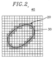
- the video frame is first divided into a plurality of blocks of K x L pixels with K and L being positive integers, respectively, and contour blocks are detected, wherein the contour block denotes a block containing at least one contour pixel.
- the contour block denotes a block containing at least one contour pixel.
- each block located in a shaded region 20 includes a portion of a contour 30 in a video frame 40 and is referred to as a contour block.
- Position information of contour pixels included within each contour block is then provided to the initial vertex determination block 110.
- the initial vertex determination block 110 detects two end points of each contour segment in each contour block and selects the detected two end points as initial vertices for the respective contour segment, wherein a contour segment represents a set of continuous contour pixels within a contour block.
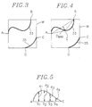
- FIG. 3 there are shown diagrams illustrating an initial vertex determination process carried out at the initial vertex determination block 110.
- a contour segment in a contour block M is of a closed loop, two farthest points on that contour segment are selected as initial vertices as in the conventional polygonal approximation technique.
- initial vertices are not determined for that contour segment.
- initial vertex data representing position information of initial vertices for such contour segment and contour segment data representing position data of the contour pixels which constitute the contour segment are transferred to the polygonal approximation block 120.
- the polygonal approximation block 120 Based on the initial vertices data and the contour segment data for each contour segment, the polygonal approximation block 120 approximates each contour segment by using a conventional approximation algorithm for fitting the contour segment by line segments.
- FIG. 4 there is illustrated a segmentation process for the exemplary contour segment 33 according to the polygonal approximation technique.
- a straight line segment AB between the initial vertices A and B of the contour segment 33 is drawn and a distance D MAX from a farthest point on the contour segment 33 to the straight line segment AB is determined. If the distance D MAX between the straight line segment AB and the farthest point, e.g., E, is greater than a predetermined threshold value, the point E is selected as an additional vertex and straight line segments AE and EB connecting the point E with A and B respectively are drawn. This procedure is repeated until the D MAX for each straight line segment becomes smaller than the predetermined threshold value.
- the number of additional vertices depends on the predetermined threshold value and the representation of the contour segment by straight line segments becomes more accurate, at the expense of coding efficiency, as the predetermined threshold value becomes smaller.
- the polygonal approximation block 120 provides via a line L10 vertex information representing positions of the vertices including the initial and the additional vertices, e.g., A, B and E, for each contour segment to the sampling & error detection block 130 and the contour coder 150, while contour segment data for each contour segment is fed to the sampling and error detection block 130 through a line L20.
- N equidistanced sample points are selected for each straight line segment between two vertices within a contour segment, N being a positive integer; and an approximation error at each of the N sample points are calculated based on the vertex information and the contour segment data, wherein the approximation error at a sample point represents a distance between a straight line segment and the contour segment at the sample point.
- Fig. 5 illustrates an exemplary diagram representing approximation errors between straight line segment AE and corresponding contour segment.
- Each of the approximation errors d1 to d4 represents the distance from each of sample points s1 to s4 on the line segment AE to the corresponding contour segment, wherein the approximation errors at the vertices A and E are all "zeros".
- each approximation error includes a sign determined in a predetermined manner in order for a decoder in a receiving end to be able to recognize which side of the line segment a portion of the contour segment, i.e., a contour pixel, represented by each approximation error resides.
- a set of approximation errors for each straight line segment is then applied to the transform and quantization block 140
- the transform and quantization block 140 transforms, first, each set of the approximation errors into a set of transform coefficients by employing, e.g., a discrete sine transform (DST), wherein the approximation errors for each set may include the approximation errors at N sample points and two vertices of each line segment or just the approximation errors at N sample points. And the set of transform coefficients are then quantized by using a known quantization method and a set of the quantized transform coefficients corresponding to each line segment are provided to the contour coder 150 for further processing.
- DST discrete sine transform
- each set of the quantized transform coefficients is encoded, e.g., by using a binary arithmetic code of JPEC(Joint Photographic Experts Group), while the vertex information from the polygonal approximation block 120 is encoded by using, e.g., a fixed length code without compression since the vertices are sparsely correlated.
- the encoded digital signals comprising the encoded quantized transform coefficients and vertex information are transmitted to a transmitter for the transmission thereof.
Abstract
Description
Claims (14)
- A method for encoding a contour image of an object contained in a video frame of a video signal, wherein the contour image includes a plurality of contour pixels, the contour pixels representing pixels located on the contour image, comprising the steps of:(a) dividing the video frame into a multiplicity of blocks, each of the blocks including K x L pixels with K and L being positive integers, respectively;(b) detecting contour blocks, each of the contour blocks including one or more contour pixels therein; and(c) coding the contour image on a contour block-by-contour block basis.
- The method in accordance with claim 1, wherein said step (c) includes the steps of:(c1) determining a plurality of vertices on each contour segment included in each contour block, said each contour segment representing a set of continuous contour pixels included in each contour block; and(c2) coding the contour image based on the vertices on each contour segment.
- The method in accordance with claim 2, wherein said step (c1) includes the steps of:(c11) determining two vertices on each contour segment; and(c12) finding additional vertices on each contour segment until a maximum distance between said each contour segment and each straight line segment connecting two adjacent vertices on said each contour segment becomes smaller than a predetermined threshold value.
- The method in accordance with claim 3, wherein two end points of said each contour segment are selected as said two vertices determined in said step (c11) if said each contour segment is of an open loop.
- The method in accordance with claim 4, wherein said step (c2) includes the steps of:(c21) determining a predetermined number of sample points on each straight line segment joining two adjacent vertices on each contour segment;(c22) calculating an error at each of the sample points and the vertices on each straight line segment, the error representing a distance between the straight line segment and its corresponding contour segment;(c23) transforming a set of errors into a set of transform coefficients;(c24) converting the set of transform coefficients into a set of quantized transform coefficients; and(c25) coding the set of quantized transform coefficients.
- The method in accordance with claim 5, wherein the set of errors includes the errors of the sample points on each straight line segment.
- The method in accordance with claim 5, wherein the set of errors includes the errors of the sample points and the vertices on each straight line segment.
- An apparatus for encoding a contour image of an object contained in a video frame of a video signal, wherein the contour image includes a plurality of contour pixels, the contour pixels representing pixels located on the contour image, which comprises:means for dividing the video frame into a multiplicity of blocks, each of the blocks including K x L pixels with K and L being positive integers, respectively;means for detecting contour blocks, each of the contour blocks including one or more contour pixels therein; andmeans for coding the contour image on a contour block-by-contour block basis.
- The apparatus in accordance with claim 8, wherein said contour image coding means includes:means for determining a plurality of vertices on each contour segment included in each contour block, said each contour segment representing a set of continuous contour pixels included in each contour block; andmeans for coding the contour image based on the vertices on each contour segment.
- The apparatus in accordance with claim 9, wherein said vertices determining means includes:means for determining two vertices on each contour segment; andmeans for finding additional vertices on each contour segment until a maximum distance between said each contour segment and each straight line segment connecting two adjacent vertices on said each contour segment becomes smaller than a predetermined threshold value.
- The apparatus in accordance with claim 10, wherein two end points of said each contour segment are selected as said two vertices if said each contour segment is of an open loop.
- The apparatus in accordance with claim 11, wherein said contour image coding means includes:means for determining a predetermined number of sample points on each straight line segment joining two adjacent vertices on each contour segment;means for calculating an error at each of the sample points and the vertices on each straight line segment, the error representing a distance between the straight line segment and its corresponding contour segment;means for transforming a set of errors into a set of transform coefficients;means for converting the set of transform coefficients into a set of quantized transform coefficients; andmeans for coding the set of quantized transform coefficients.
- The apparatus in accordance with claim 12, wherein the set of errors includes the errors of the sample points on each straight line segment.
- The apparatus in accordance with claim 12, wherein the set of errors includes the errors of the sample points and the vertices on each straight line segment.
Applications Claiming Priority (2)
| Application Number | Priority Date | Filing Date | Title |
|---|---|---|---|
| KR1019960027949A KR100209132B1 (en) | 1996-07-11 | 1996-07-11 | Method for coding contour in block based object coding system |
| KR2794996 | 1996-07-11 |
Publications (3)
| Publication Number | Publication Date |
|---|---|
| EP0818929A2 true EP0818929A2 (en) | 1998-01-14 |
| EP0818929A3 EP0818929A3 (en) | 2000-08-23 |
| EP0818929B1 EP0818929B1 (en) | 2006-02-22 |
Family
ID=36686714
Family Applications (1)
| Application Number | Title | Priority Date | Filing Date |
|---|---|---|---|
| EP19960115871 Expired - Lifetime EP0818929B1 (en) | 1996-07-11 | 1996-10-02 | Method and apparatus for encoding a contour image in a video signal |
Country Status (7)
| Country | Link |
|---|---|
| US (1) | US5870501A (en) |
| EP (1) | EP0818929B1 (en) |
| JP (1) | JP3917691B2 (en) |
| KR (1) | KR100209132B1 (en) |
| CN (1) | CN1115647C (en) |
| DE (1) | DE69635836T2 (en) |
| IN (1) | IN189247B (en) |
Cited By (1)
| Publication number | Priority date | Publication date | Assignee | Title |
|---|---|---|---|---|
| EP1891802A1 (en) * | 2005-05-30 | 2008-02-27 | Canon Kabushiki Kaisha | Image processing apparatus, control method thereof, and program |
Families Citing this family (21)
| Publication number | Priority date | Publication date | Assignee | Title |
|---|---|---|---|---|
| KR100212552B1 (en) * | 1996-12-23 | 1999-08-02 | 전주범 | Method and apparatus for coding counter image |
| KR100239303B1 (en) * | 1997-01-21 | 2000-01-15 | 전주범 | Method for coding initial vertex of contour image |
| KR100295798B1 (en) * | 1997-07-11 | 2001-08-07 | 전주범 | Apparatus and method for coding a binary shape signal ca pable of realizing scalability |
| IL134182A (en) | 2000-01-23 | 2006-08-01 | Vls Com Ltd | Method and apparatus for visual lossless pre-processing |
| US6753929B1 (en) | 2000-06-28 | 2004-06-22 | Vls Com Ltd. | Method and system for real time motion picture segmentation and superposition |
| US6744818B2 (en) | 2000-12-27 | 2004-06-01 | Vls Com Ltd. | Method and apparatus for visual perception encoding |
| US20040240543A1 (en) * | 2001-09-04 | 2004-12-02 | Faroudja Yves C. | Low bandwidth video compression |
| US7099518B2 (en) * | 2002-07-18 | 2006-08-29 | Tektronix, Inc. | Measurement of blurring in video sequences |
| US20040131117A1 (en) * | 2003-01-07 | 2004-07-08 | Sheraizin Vitaly S. | Method and apparatus for improving MPEG picture compression |
| US7639892B2 (en) * | 2004-07-26 | 2009-12-29 | Sheraizin Semion M | Adaptive image improvement |
| US7903902B2 (en) | 2004-07-26 | 2011-03-08 | Sheraizin Semion M | Adaptive image improvement |
| US7526142B2 (en) * | 2005-02-22 | 2009-04-28 | Sheraizin Vitaly S | Enhancement of decompressed video |
| JP4844449B2 (en) * | 2006-04-17 | 2011-12-28 | 日本ビクター株式会社 | Moving picture encoding apparatus, method, program, moving picture decoding apparatus, method, and program |
| JP4475680B2 (en) * | 2009-07-14 | 2010-06-09 | キヤノン株式会社 | Image processing apparatus, control method therefor, and program |
| JP5026604B2 (en) | 2011-02-24 | 2012-09-12 | 任天堂株式会社 | Image recognition program, image recognition apparatus, image recognition system, and image recognition method |
| JP5178860B2 (en) | 2011-02-24 | 2013-04-10 | 任天堂株式会社 | Image recognition program, image recognition apparatus, image recognition system, and image recognition method |
| JP5016723B2 (en) | 2011-02-24 | 2012-09-05 | 任天堂株式会社 | Image recognition program, image recognition apparatus, image recognition system, and image recognition method |
| JP2011134343A (en) * | 2011-02-24 | 2011-07-07 | Nintendo Co Ltd | Image processing program, image processing apparatus, image processing system, and image processing method |
| JP4967065B2 (en) | 2011-02-24 | 2012-07-04 | 任天堂株式会社 | Image processing program, image processing apparatus, image processing system, and image processing method |
| CN110751896A (en) * | 2019-10-15 | 2020-02-04 | 北京龙软科技股份有限公司 | Method and device for drawing contour line notes on mine contour line related thematic map |
| CN113132744A (en) * | 2021-03-22 | 2021-07-16 | 广州虎牙科技有限公司 | Processing method, model, electronic device and computer storage medium of live broadcast barrage |
Citations (5)
| Publication number | Priority date | Publication date | Assignee | Title |
|---|---|---|---|---|
| US4566128A (en) * | 1982-09-13 | 1986-01-21 | Dainippon Screen Seizo Kabushiki Kaisha | Method for data compression for two-value picture image |
| JPS6461870A (en) * | 1987-09-01 | 1989-03-08 | Fujitsu Ltd | Method for detecting crack distribution of ridge line of fingerprint image |
| US5335298A (en) * | 1991-08-19 | 1994-08-02 | The United States Of America As Represented By The Secretary Of The Army | Automated extraction of airport runway patterns from radar imagery |
| US5524064A (en) * | 1992-09-09 | 1996-06-04 | U.S. Philips Corporation | Device for coding still images |
| EP0734163A2 (en) * | 1995-03-18 | 1996-09-25 | Daewoo Electronics Co., Ltd | A contour approximation apparatus for representing a contour of an object |
Family Cites Families (7)
| Publication number | Priority date | Publication date | Assignee | Title |
|---|---|---|---|---|
| EP0330455A3 (en) * | 1988-02-22 | 1990-07-04 | Kabushiki Kaisha Toshiba | Image encoding apparatus |
| US5638986A (en) * | 1992-11-06 | 1997-06-17 | Fluilogic Systems Oy | Method and equipment for dosing small amounts of liquid quantitatively |
| KR970003799B1 (en) * | 1993-12-29 | 1997-03-21 | 양승택 | Image signal transferring device |
| US5594504A (en) * | 1994-07-06 | 1997-01-14 | Lucent Technologies Inc. | Predictive video coding using a motion vector updating routine |
| JP3038143B2 (en) * | 1994-12-29 | 2000-05-08 | 現代電子産業株式会社 | Apparatus for reducing shape information for each object of video equipment, method for reducing the same, and polygon approximation method |
| KR0181052B1 (en) * | 1995-03-31 | 1999-05-01 | 배순훈 | Segmentation apparatus for high definition image system |
| KR100209798B1 (en) * | 1995-04-08 | 1999-07-15 | 전주범 | Image segment coding apparatus using extension-interpolation method |
-
1996
- 1996-07-11 KR KR1019960027949A patent/KR100209132B1/en not_active IP Right Cessation
- 1996-08-23 IN IN1504CA1996 patent/IN189247B/en unknown
- 1996-09-25 JP JP27417296A patent/JP3917691B2/en not_active Expired - Fee Related
- 1996-09-26 US US08/721,638 patent/US5870501A/en not_active Expired - Lifetime
- 1996-10-02 DE DE1996635836 patent/DE69635836T2/en not_active Expired - Lifetime
- 1996-10-02 EP EP19960115871 patent/EP0818929B1/en not_active Expired - Lifetime
- 1996-10-03 CN CN96119949A patent/CN1115647C/en not_active Expired - Fee Related
Patent Citations (5)
| Publication number | Priority date | Publication date | Assignee | Title |
|---|---|---|---|---|
| US4566128A (en) * | 1982-09-13 | 1986-01-21 | Dainippon Screen Seizo Kabushiki Kaisha | Method for data compression for two-value picture image |
| JPS6461870A (en) * | 1987-09-01 | 1989-03-08 | Fujitsu Ltd | Method for detecting crack distribution of ridge line of fingerprint image |
| US5335298A (en) * | 1991-08-19 | 1994-08-02 | The United States Of America As Represented By The Secretary Of The Army | Automated extraction of airport runway patterns from radar imagery |
| US5524064A (en) * | 1992-09-09 | 1996-06-04 | U.S. Philips Corporation | Device for coding still images |
| EP0734163A2 (en) * | 1995-03-18 | 1996-09-25 | Daewoo Electronics Co., Ltd | A contour approximation apparatus for representing a contour of an object |
Non-Patent Citations (2)
| Title |
|---|
| FREEMAN H.: "AN ITERATIVE PROCEDURE FOR THE POLYGONAL APPROXIMATION PLANE CURVES" COMPUTER GRAPHICS AND IMAGE PROCESSING, 20 August 1972 (1972-08-20), XP000907652 * |
| PATENT ABSTRACTS OF JAPAN vol. 013, no. 269 (P-888), 21 June 1989 (1989-06-21) & JP 01 061870 A (FUJITSU LTD), 8 March 1989 (1989-03-08) * |
Cited By (3)
| Publication number | Priority date | Publication date | Assignee | Title |
|---|---|---|---|---|
| EP1891802A1 (en) * | 2005-05-30 | 2008-02-27 | Canon Kabushiki Kaisha | Image processing apparatus, control method thereof, and program |
| EP1891802A4 (en) * | 2005-05-30 | 2010-08-04 | Canon Kk | Image processing apparatus, control method thereof, and program |
| US8274667B2 (en) | 2005-05-30 | 2012-09-25 | Canon Kabushiki Kaisha | Image processing apparatus, control method thereof, and storage medium storing a program for converting raster image data into block vector image format |
Also Published As
| Publication number | Publication date |
|---|---|
| DE69635836T2 (en) | 2006-08-03 |
| IN189247B (en) | 2003-01-18 |
| JP3917691B2 (en) | 2007-05-23 |
| EP0818929A3 (en) | 2000-08-23 |
| KR980013430A (en) | 1998-04-30 |
| DE69635836D1 (en) | 2006-04-27 |
| US5870501A (en) | 1999-02-09 |
| JPH1079942A (en) | 1998-03-24 |
| EP0818929B1 (en) | 2006-02-22 |
| CN1171019A (en) | 1998-01-21 |
| CN1115647C (en) | 2003-07-23 |
| KR100209132B1 (en) | 1999-07-15 |
Similar Documents
| Publication | Publication Date | Title |
|---|---|---|
| EP0818929B1 (en) | Method and apparatus for encoding a contour image in a video signal | |
| US5774595A (en) | Contour approximation method for representing a contour of an object | |
| EP0801504B1 (en) | Method for encoding a contour of an object in a video signal by using a contour motion estimation technique | |
| US5691769A (en) | Apparatus for encoding a contour of an object | |
| EP0734163B1 (en) | A contour approximation apparatus for representing a contour of an object | |
| EP0806742B1 (en) | Adaptive contour coding | |
| EP0831654B1 (en) | Method and apparatus for encoding a contour image of an object in a video signal | |
| US5896467A (en) | Method and apparatus for encoding a contour image of an object in a video signal | |
| JP3924032B2 (en) | Outline coding method and outline coding apparatus | |
| US5828790A (en) | Method and apparatus for approximating a contour image of an object in a video signal | |
| US6163627A (en) | Method and apparatus for encoding a contour of an object | |
| CN1062701C (en) | Apparatus for encoding controur of object | |
| KR100207389B1 (en) | Contour encoding apparatus for object | |
| KR100243863B1 (en) | Method and apparatus for approximating a controur image of an object in a video signal | |
| KR100229534B1 (en) | Method and apparatus for coding contour information of image | |
| JP3859786B2 (en) | Coding method for contour line of object in video signal |
Legal Events
| Date | Code | Title | Description |
|---|---|---|---|
| PUAI | Public reference made under article 153(3) epc to a published international application that has entered the european phase |
Free format text: ORIGINAL CODE: 0009012 |
|
| AK | Designated contracting states |
Kind code of ref document: A2 Designated state(s): DE FR GB NL |
|
| PUAL | Search report despatched |
Free format text: ORIGINAL CODE: 0009013 |
|
| AK | Designated contracting states |
Kind code of ref document: A3 Designated state(s): DE FR GB NL |
|
| RIC1 | Information provided on ipc code assigned before grant |
Free format text: 7H 04N 7/26 A, 7G 06T 9/20 B |
|
| 17P | Request for examination filed |
Effective date: 20010223 |
|
| AKX | Designation fees paid |
Free format text: DE FR GB NL |
|
| RAP1 | Party data changed (applicant data changed or rights of an application transferred) |
Owner name: DAEWOO ELECTRONICS CORPORATION |
|
| GRAP | Despatch of communication of intention to grant a patent |
Free format text: ORIGINAL CODE: EPIDOSNIGR1 |
|
| GRAS | Grant fee paid |
Free format text: ORIGINAL CODE: EPIDOSNIGR3 |
|
| GRAA | (expected) grant |
Free format text: ORIGINAL CODE: 0009210 |
|
| AK | Designated contracting states |
Kind code of ref document: B1 Designated state(s): DE FR GB NL |
|
| REG | Reference to a national code |
Ref country code: GB Ref legal event code: FG4D |
|
| REF | Corresponds to: |
Ref document number: 69635836 Country of ref document: DE Date of ref document: 20060427 Kind code of ref document: P |
|
| ET | Fr: translation filed | ||
| PLBE | No opposition filed within time limit |
Free format text: ORIGINAL CODE: 0009261 |
|
| STAA | Information on the status of an ep patent application or granted ep patent |
Free format text: STATUS: NO OPPOSITION FILED WITHIN TIME LIMIT |
|
| 26N | No opposition filed |
Effective date: 20061123 |
|
| REG | Reference to a national code |
Ref country code: DE Ref legal event code: R082 Ref document number: 69635836 Country of ref document: DE Representative=s name: SAMSON & PARTNER, PATENTANWAELTE, DE |
|
| REG | Reference to a national code |
Ref country code: GB Ref legal event code: 732E Free format text: REGISTERED BETWEEN 20130404 AND 20130410 |
|
| REG | Reference to a national code |
Ref country code: DE Ref legal event code: R082 Ref document number: 69635836 Country of ref document: DE Representative=s name: SAMSON & PARTNER PATENTANWAELTE MBB, DE Effective date: 20130313 Ref country code: DE Ref legal event code: R082 Ref document number: 69635836 Country of ref document: DE Representative=s name: SAMSON & PARTNER, PATENTANWAELTE, DE Effective date: 20130313 Ref country code: DE Ref legal event code: R081 Ref document number: 69635836 Country of ref document: DE Owner name: MAPLE VISION TECHNOLOGIES INC., CA Free format text: FORMER OWNER: DAEWOO ELECTRONICS CORP., SEOUL/SOUL, KR Effective date: 20130313 |
|
| REG | Reference to a national code |
Ref country code: FR Ref legal event code: TP Owner name: MAPLE VISION TECHNOLOGIES INC., CA Effective date: 20131226 |
|
| PGFP | Annual fee paid to national office [announced via postgrant information from national office to epo] |
Ref country code: FR Payment date: 20141008 Year of fee payment: 19 Ref country code: DE Payment date: 20140923 Year of fee payment: 19 Ref country code: GB Payment date: 20141001 Year of fee payment: 19 |
|
| PGFP | Annual fee paid to national office [announced via postgrant information from national office to epo] |
Ref country code: NL Payment date: 20141010 Year of fee payment: 19 |
|
| REG | Reference to a national code |
Ref country code: DE Ref legal event code: R119 Ref document number: 69635836 Country of ref document: DE |
|
| GBPC | Gb: european patent ceased through non-payment of renewal fee |
Effective date: 20151002 |
|
| REG | Reference to a national code |
Ref country code: NL Ref legal event code: MM Effective date: 20151101 |
|
| PG25 | Lapsed in a contracting state [announced via postgrant information from national office to epo] |
Ref country code: GB Free format text: LAPSE BECAUSE OF NON-PAYMENT OF DUE FEES Effective date: 20151002 Ref country code: DE Free format text: LAPSE BECAUSE OF NON-PAYMENT OF DUE FEES Effective date: 20160503 |
|
| REG | Reference to a national code |
Ref country code: FR Ref legal event code: ST Effective date: 20160630 |
|
| PG25 | Lapsed in a contracting state [announced via postgrant information from national office to epo] |
Ref country code: FR Free format text: LAPSE BECAUSE OF NON-PAYMENT OF DUE FEES Effective date: 20151102 Ref country code: NL Free format text: LAPSE BECAUSE OF NON-PAYMENT OF DUE FEES Effective date: 20151101 |