EP0818874A1 - Apparatus and methods for forming and inserting multi-lobed coils constituting the stator winding of an alternator - Google Patents
Apparatus and methods for forming and inserting multi-lobed coils constituting the stator winding of an alternator Download PDFInfo
- Publication number
- EP0818874A1 EP0818874A1 EP97110542A EP97110542A EP0818874A1 EP 0818874 A1 EP0818874 A1 EP 0818874A1 EP 97110542 A EP97110542 A EP 97110542A EP 97110542 A EP97110542 A EP 97110542A EP 0818874 A1 EP0818874 A1 EP 0818874A1
- Authority
- EP
- European Patent Office
- Prior art keywords
- coil
- semi
- station
- coils
- coiling
- Prior art date
- Legal status (The legal status is an assumption and is not a legal conclusion. Google has not performed a legal analysis and makes no representation as to the accuracy of the status listed.)
- Withdrawn
Links
- 238000004804 winding Methods 0.000 title claims abstract description 20
- 238000000034 method Methods 0.000 title claims abstract description 19
- 238000003780 insertion Methods 0.000 description 3
- 230000037431 insertion Effects 0.000 description 3
- RYGMFSIKBFXOCR-UHFFFAOYSA-N Copper Chemical compound [Cu] RYGMFSIKBFXOCR-UHFFFAOYSA-N 0.000 description 2
- 238000010586 diagram Methods 0.000 description 2
- 230000007257 malfunction Effects 0.000 description 1
- 238000004519 manufacturing process Methods 0.000 description 1
Images


Classifications
-
- H—ELECTRICITY
- H02—GENERATION; CONVERSION OR DISTRIBUTION OF ELECTRIC POWER
- H02K—DYNAMO-ELECTRIC MACHINES
- H02K15/00—Processes or apparatus specially adapted for manufacturing, assembling, maintaining or repairing of dynamo-electric machines
- H02K15/06—Embedding prefabricated windings in the machines
- H02K15/062—Windings in slots; Salient pole windings
- H02K15/065—Windings consisting of complete sections, e.g. coils or waves
- H02K15/067—Windings consisting of complete sections, e.g. coils or waves inserted in parallel to the axis of the slots or inter-polar channels
- H02K15/068—Strippers; Embedding windings by strippers
-
- H—ELECTRICITY
- H02—GENERATION; CONVERSION OR DISTRIBUTION OF ELECTRIC POWER
- H02K—DYNAMO-ELECTRIC MACHINES
- H02K15/00—Processes or apparatus specially adapted for manufacturing, assembling, maintaining or repairing of dynamo-electric machines
- H02K15/04—Processes or apparatus specially adapted for manufacturing, assembling, maintaining or repairing of dynamo-electric machines of windings prior to their mounting into the machines
- H02K15/044—Processes or apparatus specially adapted for manufacturing, assembling, maintaining or repairing of dynamo-electric machines of windings prior to their mounting into the machines winding non-flat conductive wires, e.g. cables or cords
- H02K15/047—Distributed windings
- H02K15/048—Distributed windings of the wave winding type
- H02K15/0485—Distributed windings of the wave winding type manufactured by shaping an annular winding
-
- H—ELECTRICITY
- H02—GENERATION; CONVERSION OR DISTRIBUTION OF ELECTRIC POWER
- H02K—DYNAMO-ELECTRIC MACHINES
- H02K3/00—Details of windings
- H02K3/04—Windings characterised by the conductor shape, form or construction, e.g. with bar conductors
- H02K3/28—Layout of windings or of connections between windings
Definitions
- the present invention relates to apparatus and methods for forming and inserting multi-lobed coils into slots of a stator, the coils constituting the stator winding.
- the stator is of a type commonly used in an alternator in which at least some slots of the stator receive portions of two separate semi-coils angularly offset from each other by approximately one half-wave such that the lobes of one semi-coil are located in the spaces between the lobes of the other semi-coil.
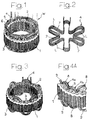
- FIG. 1 is a perspective view of a known stator of a dynamo-electric machine.
- the stator includes an annular body 1 having a laminated structure with an inner cylindrical surface 2 and a plurality of axial slots 3 formed equiangularly apart from each other.
- the winding W of the stator includes three copper wire coils 4, 5 and 6, each having the multi-lobed shape of coil 4 of FIG. 2 shown before insertion into slots 3 of the stator.
- Coil 4 has a plurality of lobes L which are equiangularly spaced apart from each other.
- a stator inserted with a single coil 4 is shown in FIG. 3. After insertion, lobes L of the coil are located on a theoretical cylindrical surface, with side portions 7 inserted into respective slots 3 of the stator.
- Multi-lobed coils 4, 5 and 6 may be formed and inserted with known apparatus, such as, for example, that described in US Patent No. 4,512,376, issued to the same inventor of the present invention.
- undulated coils of the type shown in FIG. 2 can be formed and inserted into slots of a stator.
- coils 4, 5 and 6 are each usually replaced with two semi-coils angularly offset from each other by approximately one half-wave such that the lobes of one semi-coil are located in the spaces between the lobes of the other semi-coil.
- Each slot of the stator accordingly engages two portions 7, each portion 7 forming part of a separate semi-coil. This arrangement is shown in FIGS. 4A and 4B.
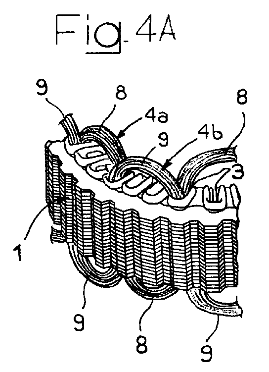
- FIG. 4A is a partial perspective view of a stator having one pair of semi-coils 4a and 4b with respective lobes 8 and 9.
- Semi-coils 4a and 4b constitute one phase of the stator's winding (which typically has three), and are angularly offset from each other by approximately one half-wave such that each lobe 8 is located in the space between two adjacent lobes 9, and each engaged slot 3 is inserted with one portion of semi-coil 4a and one portion of semi-coil 4b.
- FIG. 4B is a simplified diagram of a stator laid out in a plane with semi-coils 4a and 4b inserted in some slots 3.
- apparatus for forming and inserting multi-lobed coils into slots of a stator, the coils constituting the winding of the stator.
- the apparatus includes a first coiling station for forming and loading at least one multi-lobed semi-coil onto a coil-inserting tool, a second coiling station for forming and loading at least one multi-lobed semi-coil onto a coil-inserting tool, an inserting station for inserting semi-coils into at least some slots of a stator, and means for transferring a coil-inserting tool from each station to at least one other station.
- Apparatus 10 includes a base structure 11 that supports a rotatable platform 12.
- Rotatable platform 12 supports three coil-inserting tools 14 positioned at stations A, B and C, respectively.
- Motor means (known in the art and not shown) is provided within base structure 11 to drive rotatable platform 12 about a vertical axis 13 to substantially simultaneously transfer the coil-inserting tool 14 at station A to station B, the coil-inserting tool 14 at station B to station C, and the coil-inserting tool 14 at station C to station A.
- Coil-inserting tools 14 are known in the art and may be of the type shown, for example, in U.S. Patent No. 3,324,536. Such coil-inserting tools are loaded with one or more multi-lobed coils and are then positioned to insert those coils into slots of a stator.
- Apparatus 10 further includes an upright 15 which extends upwardly from base structure 11.
- Upright 15 supports winding heads 16 and 17 and an inserting device 18.
- Winding heads 16 and 17 are identical and respectively located at stations A and B, while inserting device 18 is located at station C.
- Stations A and B are coiling stations and station C is an inserting station.
- Winding heads 16 and 17 are known in the art and may be of the type shown, for example, in U.S. Patent No. 4,512,376, which is incorporated by reference herein. Winding heads 16 and 17 are each supplied with a copper wire provided by a reel of wire (not shown) located within container 19 to form multi-lobed coils having configuration as shown in FIG. 2. Winding heads 16 and 17 further load these coils onto coil-inserting tools 14.
- Inserting device 18 is also known in the art and includes any device at which a stator can be positioned on a coil-inserting tool 14 to enable the coil-inserting tool, which was previously loaded with semi-coils, to insert those semi-coils into the slots of the stator.
- Apparatus 10 operates typically as follows: an empty coil-inserting tool 14 is transferred to station A from inserting station C, where coils previously loaded onto the coil-inserting tool 14 were inserted into at least some slots of a stator.
- winding head 16 forms a semi-coil (e.g., semi-coil 4a or 4b of FIGS. 4A and 4B) having the configuration shown in FIG. 2. Winding head 16 then loads this semi-coil onto the empty coil-inserting tool 14.
- the coil-inserting tool at station B which was previously loaded with a first semi-coil at coiling station A, is loaded with a second semi-coil angularly offset from the first by approximately one half-wave.
- the coil-inserting tool at inserting station C which was previously loaded with angularly offset semi-coils formed and loaded at coiling stations A and B, respectively, inserts the angularly offset semi-coils into at least some slots of a stator positioned at station C, each engaged slot receiving portions of both semi-coils. (Typically a third of the slots are inserted with semi-coils if the semi-coils constitute one phase of a three phase stator winding.)
- Rotatable platform 12 then rotates such that the coil-inserting tool 14 at coiling station A is transferred to coiling station B, the coil-inserting tool 14 at coiling station B is transferred to inserting station C, and the coil-inserting tool 14 at inserting station C is transferred to coiling station A.
- the coil-inserting tool 14 that was loaded with a first semi-coil at coiling station A can now be loaded with a second semi-coil at coiling station B, the second semi-coil being angularly offset from the first by approximately one half-wave.
- the coil-inserting tool 14 that was loaded with a second semi-coil angularly offset from the first semi-coil at coiling station B can now insert its coils into some of the slots of a stator at inserting station C, and the coil-inserting tool 14 that inserted its coils into some of the slots of a stator at inserting station C can now be loaded with another first semi-coil at coiling station A.
- Rotatable platform 12 then rotates similarly again to complete an operational cycle.
- a stator either remains at inserting station C until all pairs of semi-coils (i.e., phases) are inserted, or is transferred to another apparatus 10 to receive another phase of its winding. In either case, the stator is replaced with another stator to be inserted with coils.
- coil inserting station C may alternatively receive coil-inserting tools 14 loaded with angularly offset pairs of semi-coils directly from either first coiling station A or second coiling station B.
- This enhanced versatility permits apparatus 10 to continue production should one of the coiling stations malfunction.
- coiling stations A and B each form and load onto respective coil-inserting tools 14 two semi-coils angularly offset from each other by approximately one half-wave such that the lobes of one semi-coil are located in the spaces between the lobes of the other semi-coil.
- Transferring means preferably transfers loaded coil-inserting tools 14 from either coiling station A or B directly to inserting station C.
- rotatable platform 12 merely rotates in a direction opposite that for transferring a coil-inserting tool 14 from coiling station A to coiling station B.
- an empty coil-inserting tool 14 from inserting station C is substantially simultaneously transferred to coiling station B.
- Apparatus 10 can therefore be advantageously operated with either coiling stations A and B working together to form and load angularly offset pairs of semi-coils onto coil-inserting tools, or independently, where each separately forms and loads a pair of angularly offset semi-coils onto a respective coil-inserting tool.
- Means for transferring coil-inserting tools 14 from station to station can alternatively be provided by other than rotatable platform 12 and the motor means described above.
- transferring means may include, similar to what is provided in our Italian Patent Application TO96A000555, filed June 28, 1996, which is incorporated by reference herein, a transfer station located centrally between the coiling and inserting stations, and exchange means interposed between each of the coiling and inserting stations and the transfer station.
- Exchange means exchanges a coil-inserting tool 14 at each of the coiling and inserting stations with a coil-inserting tool 14 at the transfer station.
- the alternative transferring means may operate, for example, as follows: exchange means exchanges a first coil-inserting tool 14 loaded with a first semi-coil at coiling station A with an empty coil-inserting tool 14 at transfer station.
- the first coil-inserting tool 14, now at the transfer station, is then exchanged with a coil-inserting tool 14 at coiling station B.
- the first coil-inserting tool 14 is loaded with a second semi-coil, formed at coiling station B, such that the second semi-coil is angularly offset from the first semi-coil by approximately one half-wave.
- the first coil-inserting tool 14 is then exchanged with a coil-inserting tool 14 at the transfer station. From the transfer station, the first coil-inserting tool 14 is exchanged with a coil-inserting tool 14 at inserting station C. At inserting station C, the first coil-inserting tool 14 inserts the first and second semi-coils into at least some slots of a stator. Exchange means then transfers the first coil-inserting tool 14 back to coiling station A via the transfer station.
- alternative transferring means can be used to produce alternator stators with windings constituted by pairs of angularly offset multi-lobed semi-coils.
- the transfer station and exchange means can also be used when coiling station A and B operate independently.
- a coil-inserting tool loaded at coiling station A is transferred to the transfer station, where, instead of then being transferred to coiling station B, it is transferred to inserting station C.
- a coil-inserting tool loaded with a pair of angularly offset semi-coils at coiling station B is transferred to the transfer station and then to coil-inserting station C via the transfer station.
- apparatus and methods are presented for forming and loading onto a coil-inserting tool multi-lobed semi-coils angularly offset from each other by approximately one half-wave such that the lobes of one semi-coil are located in the spaces between the lobes of the other semi-coil, and for inserting those coils into at least some slots of a stator for an alternator.
- a coil-inserting tool multi-lobed semi-coils angularly offset from each other by approximately one half-wave such that the lobes of one semi-coil are located in the spaces between the lobes of the other semi-coil, and for inserting those coils into at least some slots of a stator for an alternator.
Landscapes
- Engineering & Computer Science (AREA)
- Power Engineering (AREA)
- Manufacturing & Machinery (AREA)
- Manufacture Of Motors, Generators (AREA)
- Windings For Motors And Generators (AREA)
Abstract
Apparatus (10) and methods are presented for forming
and inserting multi-lobed coils into slots (3) of a stator
for an alternator, the coils constituting the winding
of the stator. The apparatus includes first and second
coiling stations (A,B) and a coil inserting station (C). The
first and second coiling stations form and load, either
sequentially or independently, a coil-inserting tool (14)
with first and second multi-lobed semi-coils (4a,4b) angularly
offset from each other by approximately one half-wave
such that the lobes (9) of one semi-coil (4b) are located in the
spaces between the lobes (8) of the other semi-coil (4a). The
coil-inserting tool (14) is then transferred to the coil
inserting station (C) where the first and second semi-coils (4a,4b)
are substantially simultaneously inserted into at least
some slots (3) of a stator, each engaged slot receiving a
portion of both first and second semi-coils.
Description
The present invention relates to apparatus and
methods for forming and inserting multi-lobed coils
into slots of a stator, the coils constituting the
stator winding. The stator is of a type commonly used
in an alternator in which at least some slots of the
stator receive portions of two separate semi-coils
angularly offset from each other by approximately one
half-wave such that the lobes of one semi-coil are
located in the spaces between the lobes of the other
semi-coil.
FIG. 1 is a perspective view of a known stator of
a dynamo-electric machine. The stator includes an
annular body 1 having a laminated structure with an
inner cylindrical surface 2 and a plurality of axial
slots 3 formed equiangularly apart from each other. The
winding W of the stator includes three copper wire
coils 4, 5 and 6, each having the multi-lobed shape of
coil 4 of FIG. 2 shown before insertion into slots 3 of
the stator. Coil 4 has a plurality of lobes L which are
equiangularly spaced apart from each other. A stator
inserted with a single coil 4 is shown in FIG. 3. After
insertion, lobes L of the coil are located on a
theoretical cylindrical surface, with side portions 7
inserted into respective slots 3 of the stator.
Currently, a need exists for providing stators
that can be used in alternators, particularly for
automotive use. In such stators, coils 4, 5 and 6 are
each usually replaced with two semi-coils angularly
offset from each other by approximately one half-wave
such that the lobes of one semi-coil are located in the
spaces between the lobes of the other semi-coil. Each
slot of the stator accordingly engages two portions 7,
each portion 7 forming part of a separate semi-coil.
This arrangement is shown in FIGS. 4A and 4B.
FIG. 4A is a partial perspective view of a stator
having one pair of semi-coils 4a and 4b with respective
lobes 8 and 9. Semi-coils 4a and 4b constitute one
phase of the stator's winding (which typically has
three), and are angularly offset from each other by
approximately one half-wave such that each lobe 8 is
located in the space between two adjacent lobes 9, and
each engaged slot 3 is inserted with one portion of
semi-coil 4a and one portion of semi-coil 4b. FIG. 4B
is a simplified diagram of a stator laid out in a plane
with semi-coils 4a and 4b inserted in some slots 3.
Known apparatus of this type described in U.S.
Patent No. 4,512,376 pertains only generally to forming
and inserting multi-lobed coils for stators of dynamo-electric
machines. Thus, there is no teaching, or even
a remote suggestion, of apparatus or methods for
forming two semi-coils angularly offset from each other
by approximately one half-wave such that the lobes of
one semi-coil are located in the spaces between the
lobes of the other semi-coil. Nor is there a teaching
or suggestion of apparatus or methods for inserting
respective portions of such angularly offset semi-coils
into the same slots of a stator.
In view of the foregoing, it would be desirable to
provide apparatus and methods for forming and inserting
into slots of a stator for an alternator multi-lobed
semi-coils angularly offset from each other by
approximately one half-wave such that the lobes of one
semi-coil are located in the spaces between the lobes
of the other semi-coil.
It would also be desirable to provide apparatus
and methods that are simple, efficient, and reliable
for forming and inserting into slots of a stator for an
alternator multi-lobed semi-coils angularly offset from
each other by approximately one half-wave such that the
lobes of one semi-coil are located in the spaces
between the lobes of the other semi-coil.
It is an object of this invention to provide
apparatus and methods for forming and inserting into
slots of a stator for an alternator multi-lobed semi-coils
angularly offset from each other by approximately
one half-wave such that the lobes of one semi-coil are
located in the spaces between the lobes of the other
semi-coil.
It is also an object of this invention to provide
apparatus and methods that are simple, efficient, and
reliable for forming and inserting into slots of a
stator for an alternator multi-lobed semi-coils
angularly offset from each other by approximately one
half-wave such that the lobes of one semi-coil are
located in the spaces between the lobes of the other
semi-coil.
In accordance with this invention, there is
provided apparatus for forming and inserting multi-lobed
coils into slots of a stator, the coils
constituting the winding of the stator. The apparatus
includes a first coiling station for forming and
loading at least one multi-lobed semi-coil onto a coil-inserting
tool, a second coiling station for forming
and loading at least one multi-lobed semi-coil onto a
coil-inserting tool, an inserting station for inserting
semi-coils into at least some slots of a stator, and
means for transferring a coil-inserting tool from each
station to at least one other station.
The above and other objects and advantages of the
invention will be apparent upon consideration of the
following detailed description, taken in conjunction
with the accompanying drawings, in which like reference
characters refer to like parts throughout, and in
which:
An exemplary embodiment of apparatus is shown in
FIGS. 5-7, in accordance with the principles of the
present invention. Apparatus 10 includes a base
structure 11 that supports a rotatable platform 12.
Rotatable platform 12 supports three coil-inserting
tools 14 positioned at stations A, B and C,
respectively. Motor means (known in the art and not
shown) is provided within base structure 11 to drive
rotatable platform 12 about a vertical axis 13 to
substantially simultaneously transfer the coil-inserting
tool 14 at station A to station B, the coil-inserting
tool 14 at station B to station C, and the
coil-inserting tool 14 at station C to station A.
Coil-inserting tools 14 are known in the art and
may be of the type shown, for example, in U.S. Patent
No. 3,324,536. Such coil-inserting tools are loaded
with one or more multi-lobed coils and are then
positioned to insert those coils into slots of a
stator.
Inserting device 18 is also known in the art and
includes any device at which a stator can be positioned
on a coil-inserting tool 14 to enable the coil-inserting
tool, which was previously loaded with semi-coils,
to insert those semi-coils into the slots of the
stator.
A stator either remains at inserting station C
until all pairs of semi-coils (i.e., phases) are
inserted, or is transferred to another apparatus 10 to
receive another phase of its winding. In either case,
the stator is replaced with another stator to be
inserted with coils.
Advantageously, coil inserting station C may
alternatively receive coil-inserting tools 14 loaded
with angularly offset pairs of semi-coils directly from
either first coiling station A or second coiling
station B. This enhanced versatility permits apparatus
10 to continue production should one of the coiling
stations malfunction. Preferably, coiling stations A
and B each form and load onto respective coil-inserting
tools 14 two semi-coils angularly offset from each
other by approximately one half-wave such that the
lobes of one semi-coil are located in the spaces
between the lobes of the other semi-coil.
Transferring means preferably transfers loaded
coil-inserting tools 14 from either coiling station A
or B directly to inserting station C. For example, to
transfer a coil-inserting tool 14 from coiling station
A directly to inserting station C, rotatable platform
12 merely rotates in a direction opposite that for
transferring a coil-inserting tool 14 from coiling
station A to coiling station B. Moreover, while
transferring coil-inserting tool 14 from coiling
station A to inserting station C, an empty coil-inserting
tool 14 from inserting station C is
substantially simultaneously transferred to coiling
station B. Transferring coil-inserting tools 14 from
coiling station B to inserting station C, while also
transferring empty coil-inserting tools 14 from
inserting station C to coiling station A, are performed
in the same manner as described above for typical
operation. Apparatus 10 can therefore be advantageously
operated with either coiling stations A and B working
together to form and load angularly offset pairs of
semi-coils onto coil-inserting tools, or independently,
where each separately forms and loads a pair of
angularly offset semi-coils onto a respective coil-inserting
tool.
Means for transferring coil-inserting tools 14
from station to station can alternatively be provided
by other than rotatable platform 12 and the motor means
described above. For example, transferring means may
include, similar to what is provided in our Italian
Patent Application TO96A000555, filed June 28, 1996,
which is incorporated by reference herein, a transfer
station located centrally between the coiling and
inserting stations, and exchange means interposed
between each of the coiling and inserting stations and
the transfer station. Exchange means exchanges a coil-inserting
tool 14 at each of the coiling and inserting
stations with a coil-inserting tool 14 at the transfer
station.
To form and insert a pair of angularly offset
semi-coils into a stator, the alternative transferring
means may operate, for example, as follows: exchange
means exchanges a first coil-inserting tool 14 loaded
with a first semi-coil at coiling station A with an
empty coil-inserting tool 14 at transfer station. The
first coil-inserting tool 14, now at the transfer
station, is then exchanged with a coil-inserting tool
14 at coiling station B. At coiling station B, the
first coil-inserting tool 14 is loaded with a second
semi-coil, formed at coiling station B, such that the
second semi-coil is angularly offset from the first
semi-coil by approximately one half-wave. The first
coil-inserting tool 14 is then exchanged with a coil-inserting
tool 14 at the transfer station. From the
transfer station, the first coil-inserting tool 14 is
exchanged with a coil-inserting tool 14 at inserting
station C. At inserting station C, the first coil-inserting
tool 14 inserts the first and second semi-coils
into at least some slots of a stator. Exchange
means then transfers the first coil-inserting tool 14
back to coiling station A via the transfer station.
Thus alternative transferring means can be used to
produce alternator stators with windings constituted by
pairs of angularly offset multi-lobed semi-coils.
In addition, the transfer station and exchange
means can also be used when coiling station A and B
operate independently. A coil-inserting tool loaded at
coiling station A is transferred to the transfer
station, where, instead of then being transferred to
coiling station B, it is transferred to inserting
station C. Similarly, a coil-inserting tool loaded with
a pair of angularly offset semi-coils at coiling
station B is transferred to the transfer station and
then to coil-inserting station C via the transfer
station.
Thus it is seen that apparatus and methods
are presented for forming and loading onto a coil-inserting
tool multi-lobed semi-coils angularly offset
from each other by approximately one half-wave such
that the lobes of one semi-coil are located in the
spaces between the lobes of the other semi-coil, and
for inserting those coils into at least some slots of a
stator for an alternator. Persons skilled in the art
will appreciate that the present invention can be
practiced by other than the described embodiments,
which are presented for purposes of illustration and
not of limitation, and the present invention is limited
only by the claims which follow.
Claims (19)
- An apparatus for forming and inserting multi-lobed coils into slots of a stator of an alternator, said coils constituting the winding of said stator, said stator being of a type in which at least some of said slots of said stator receive portions of two separate semi-coils, angularly offset from each other by approximately one half-wave such that the lobes of one semi-coil are located in the spaces between the lobes of the other semi-coil, said apparatus comprising:a first coiling station for forming at least one multi-lobed semi-coil and for loading said at least one semi-coil onto a coil-inserting tool;a second coiling station for forming at least one multi-lobed semi-coil and for loading said at least one semi-coil onto a coil-inserting tool;a coil inserting station for inserting semi-coils from a coil-inserting tool into at least some slots of a stator; andmeans for transferring a coil-inserting tool from each of said stations to at least one other of said stations.
- The apparatus of claim 1 wherein said first coiling station forms and loads onto coil-inserting tool a first multi-lobed semi-coil and said second coiling station forms and loads onto said coil-inserting tool a second multi-lobed semi-coil, said first and second semi-coils being angularly offset from each other by approximately one half-wave such that the lobes of one semi-coil are located in the spaces between the lobes of the other semi-coil.
- The apparatus of claim 2 wherein said inserting station inserts substantially simultaneously said first and second semi-coils into at least some slots of a stator, said at least some slots receiving portions of both said first and second semi-coils.
- The apparatus of claim 1 wherein said first coiling station forms and loads onto a coil-inserting tool first and second multi-lobed semi-coils, said first and second semi-coils being angularly offset from each other by approximately one half-wave such that the lobes of one semi-coil are located in the spaces between the lobes of the other semi-coil.
- The apparatus of claim 4 wherein said inserting station inserts substantially simultaneously said first and second semi-coils into at least some slots of a stator, said at least some slots receiving portions of both said first and second semi-coils.
- The apparatus of claim 1 wherein said second coiling station forms and loads onto a coil-inserting tool first and second multi-lobed semi-coils, said first and second semi-coils being angularly offset from each other by approximately one half-wave such that the lobes of one semi-coil are located in the spaces between the lobes of the other semi-coil.
- The apparatus of claim 6 wherein said inserting station inserts substantially simultaneously said first and second semi-coils into at least some slots of a stator, said at least some slots receiving portions of both said first and second semi-coils.
- The apparatus of claim 1 wherein said transferring means comprises a platform rotatable about a vertical axis.
- The apparatus of claim 1 wherein said transporting means sequentially transfers a coil-inserting tool from said inserting station to said first coiling station, from said first coiling station to said second coiling station, and from said second coiling station to said inserting station.
- The apparatus of claim 1 wherein said transporting means substantially simultaneously transfers a first coil-inserting tool from said inserting station to said first coiling station, a second coil-inserting tool from said first coiling station to said second coiling station, and a third coil-inserting tool from said second coiling station to said inserting station.
- The apparatus of claim 1 wherein said transporting means transfers a coil-inserting tool from said first coiling station to said inserting station and a second coil-inserting tool from said second coiling station to said inserting station.
- The apparatus of claim 1 wherein said transporting means comprises:a transfer station centrally located between said inserting station and said first and second coiling stations; andexchange means interposed between each of said coiling and inserting stations and said transfer station.
- A method of forming multi-lobed coils for use as the winding of a stator for an alternator and for inserting said coils into at least some slots of said stator, said stator being of a type in which at least some of said slots receive portions of two separate semi-coils angularly offset from each other by approximately one half-wave such that the lobes of one semi-coil are located in the spaces between the lobes of the other semi-coil, said method comprising the steps of:forming at least one multi-lobed semi-coil at a first coiling station;loading said at least one semi-coil formed at said first coiling station onto a coil-inserting tool at said first coiling station;forming at least one multi-lobed semi-coil at a second coiling station;loading said at least one semi-coil formed at said second coiling station onto a coil-inserting tool at said second coiling station;transferring a coil-inserting tool loaded with first and second semi-coils to an inserting station, said first and second semi-coils being angularly offset from each other by approximately one half-wave such that the lobes of one semi-coil are located in the spaces between the lobes of the other semi-coil; andinserting substantially simoultaneously said first and second semi-coils into at least some slots of said stator positioned at said inserting station, such that said at least some slots receive portions of both said first and second semi-coils.
- The method of claim 13 wherein the steps of forming and loading at least one multi-lobed semi-coil, at a first coiling station comprise the steps of forming a first and second multi-lobed semi-coil at said first coiling station and loading said first and second multi-lobed semi-coils onto a coil-inserting tool at said first coiling station, said first and second semi-coils being angularly offset from each other by approximately one half-wave such that the lobes of one semi-coil are located in the spaces between the lobes of the other semi-coil, and wherein the step of transferring comprises the step of transferring said coil-inserting tool from said first coiling station to said inserting station.
- The method of claim 13 wherein the steps of forming and loading at least one multi-lobed semi-coil, at a second coiling station comprise the steps of forming a first and second multi-lobed semi-coil at said second coiling station and loading said first and second multi-lobed semi-coils onto a coil-inserting tool at said second coiling station, said first and second semi-coils being angularly offset from each other by approximately one half-wave such that the lobes of one semi-coil are located in the spaces between the lobes of the other semi-coil, and wherein the step of transferring comprises the step of transferring said coil-inserting tool from said second coiling station to said inserting station.
- A method of forming multi-lobed coils for use as the winding of a stator for an alternator and of inserting said coils into at least some slots of said stator, said stator being of a type in which at least some of said slots receive portions of two separate semi-coils angularly offset from each other by approximately one half-wave such that the lobes of one semi-coil are located in the spaces between the lobes of the other semi-coil, said method comprising the steps of:forming a first multi-lobed semi-coil at a first coiling station;loading said first semi-coil onto a coil-inserting tool at said first coiling station;transferring said coil-inserting tool from said first coiling station to a second coiling station;forming a second multi-lobed semi-coil at said second coiling station;loading said second semi-coil onto said coil-inserting tool at said second coiling station, said first and second multi-lobed semi-coils being angularly offset from each other by approximately one half-wave such that the lobes of one semi-coil are located in the spaces between the lobes of the other semi-coil;transferring said coil-inserting tool to an inserting station;inserting substantially simultaneously said first and second semi-coils into at least some slots of said stator positioned at said inserting station such that said at least some slots receive portions of both said first and second semi-coils.
- The method of claim 16 comprising the additional step of:transferring an empty coil-inserting tool from said inserting station to said first coiling station.
- The method of claim 16 wherein said step of transferring said coil-inserting tool from said first coiling station to a second coiling station comprises the additional step of:transferring an empty coil-inserting tool from said inserting station to said first coiling station; andtransferring a coil-inserting tool loaded with third and fourth multi-lobed semi-coils from said second coiling station to said inserting station, said third and fourth multi-lobed semi-coils being angularly offset from each other by approximately one half-wave such that the lobes of one semi-coil are located in the spaces between the lobes of the other semi-coil.
- The method of claim 16 wherein said step of transferring said coil-inserting tool from said second coiling station to an inserting station comprises the additional step of:transferring an empty coil-inserting tool from said inserting station to said first coiling station; andtransferring a coil-inserting tool loaded with a fifth multi-lobed semi-coils from said first coiling station to said second coiling station.
Applications Claiming Priority (2)
| Application Number | Priority Date | Filing Date | Title |
|---|---|---|---|
| IT96TO000554A IT1286132B1 (en) | 1996-06-28 | 1996-06-28 | EQUIPMENT AND PROCEDURE FOR THE FORMING AND INSERTING OF MULTI-LOBED COILS CONSTITUTING THE STATOR WINDING OF A |
| ITTO960554 | 1996-06-28 |
Publications (1)
| Publication Number | Publication Date |
|---|---|
| EP0818874A1 true EP0818874A1 (en) | 1998-01-14 |
Family
ID=11414744
Family Applications (1)
| Application Number | Title | Priority Date | Filing Date |
|---|---|---|---|
| EP97110542A Withdrawn EP0818874A1 (en) | 1996-06-28 | 1997-06-27 | Apparatus and methods for forming and inserting multi-lobed coils constituting the stator winding of an alternator |
Country Status (3)
| Country | Link |
|---|---|
| EP (1) | EP0818874A1 (en) |
| CA (1) | CA2209218A1 (en) |
| IT (1) | IT1286132B1 (en) |
Cited By (6)
| Publication number | Priority date | Publication date | Assignee | Title |
|---|---|---|---|---|
| DE19900922C1 (en) * | 1999-01-13 | 2000-09-21 | Elmotec Elektro Motoren Tech | Method and device for producing a shaft winding for stators or rotors of electrical machines |
| US6386243B1 (en) | 1999-04-13 | 2002-05-14 | Axis Usa, Inc. | Lead formation in undulated coils for dynamo-electric machine stators |
| FR2832265A1 (en) * | 2000-09-25 | 2003-05-16 | Denso Corp | ROTATING ELECTRIC MACHINE AND METHOD FOR MANUFACTURING THE SAME |
| US6848479B2 (en) | 2001-11-16 | 2005-02-01 | Axis Usa, Inc. | Dynamo-electric machine component core winding methods and apparatus |
| WO2015092069A3 (en) * | 2013-12-20 | 2015-11-19 | Robert Bosch Gmbh | Method for producing a multi-phase winding for a stator of an electrical machine |
| CN111564306A (en) * | 2020-05-22 | 2020-08-21 | 潍坊万隆电气股份有限公司 | Similar sine type coil press forming equipment for generator stator |
Citations (8)
| Publication number | Priority date | Publication date | Assignee | Title |
|---|---|---|---|---|
| US3579818A (en) * | 1969-03-11 | 1971-05-25 | Gen Electric | Method and apparatus for forming shaped insulators and for developing coils of a magnetic core |
| US3625261A (en) * | 1969-07-29 | 1971-12-07 | Industra Products | Apparatus for winding and placing coils in the slots of a stator |
| FR2090596A5 (en) * | 1970-04-24 | 1972-01-14 | Balzer & Droell Kg | |
| GB2069376A (en) * | 1980-02-11 | 1981-08-26 | Pavesi & C Spa Off Mec | Device for inserting pre-wound coils into stator slots |
| US4416058A (en) * | 1981-12-17 | 1983-11-22 | Essex Group Incorporated | Apparatus for winding coils and inserting coils and wedges into stator cores |
| GB2127331A (en) * | 1982-09-30 | 1984-04-11 | Industra Products | Device for forming electrical coils and transferring the coils for subsequent insertion into a slotted magnetic core |
| GB2160797A (en) * | 1984-06-20 | 1986-01-02 | Hitachi Ltd | Method of winding an a.c. generator stator |
| EP0209091A2 (en) * | 1985-07-15 | 1987-01-21 | Mitsubishi Denki Kabushiki Kaisha | A method of manufacturing an armature of an a.c. generator for a car |
-
1996
- 1996-06-28 IT IT96TO000554A patent/IT1286132B1/en active IP Right Grant
-
1997
- 1997-06-27 CA CA002209218A patent/CA2209218A1/en not_active Abandoned
- 1997-06-27 EP EP97110542A patent/EP0818874A1/en not_active Withdrawn
Patent Citations (8)
| Publication number | Priority date | Publication date | Assignee | Title |
|---|---|---|---|---|
| US3579818A (en) * | 1969-03-11 | 1971-05-25 | Gen Electric | Method and apparatus for forming shaped insulators and for developing coils of a magnetic core |
| US3625261A (en) * | 1969-07-29 | 1971-12-07 | Industra Products | Apparatus for winding and placing coils in the slots of a stator |
| FR2090596A5 (en) * | 1970-04-24 | 1972-01-14 | Balzer & Droell Kg | |
| GB2069376A (en) * | 1980-02-11 | 1981-08-26 | Pavesi & C Spa Off Mec | Device for inserting pre-wound coils into stator slots |
| US4416058A (en) * | 1981-12-17 | 1983-11-22 | Essex Group Incorporated | Apparatus for winding coils and inserting coils and wedges into stator cores |
| GB2127331A (en) * | 1982-09-30 | 1984-04-11 | Industra Products | Device for forming electrical coils and transferring the coils for subsequent insertion into a slotted magnetic core |
| GB2160797A (en) * | 1984-06-20 | 1986-01-02 | Hitachi Ltd | Method of winding an a.c. generator stator |
| EP0209091A2 (en) * | 1985-07-15 | 1987-01-21 | Mitsubishi Denki Kabushiki Kaisha | A method of manufacturing an armature of an a.c. generator for a car |
Cited By (10)
| Publication number | Priority date | Publication date | Assignee | Title |
|---|---|---|---|---|
| DE19900922C1 (en) * | 1999-01-13 | 2000-09-21 | Elmotec Elektro Motoren Tech | Method and device for producing a shaft winding for stators or rotors of electrical machines |
| US6477762B1 (en) | 1999-01-13 | 2002-11-12 | Elmotec Statomat Vertriebs Gmbh | Method and device for producing a wave winding for stators or rotors of electric engines |
| US6386243B1 (en) | 1999-04-13 | 2002-05-14 | Axis Usa, Inc. | Lead formation in undulated coils for dynamo-electric machine stators |
| US6536094B2 (en) | 1999-04-13 | 2003-03-25 | Axis Usa, Inc. | Lead formation in undulated coils for dynamo-electric machine stators |
| EP1045508A3 (en) * | 1999-04-13 | 2003-09-03 | PAVESI S.r.l. | Lead formation in undulated coils for dynamo-electric machine stator |
| FR2832265A1 (en) * | 2000-09-25 | 2003-05-16 | Denso Corp | ROTATING ELECTRIC MACHINE AND METHOD FOR MANUFACTURING THE SAME |
| US7143506B2 (en) | 2000-09-25 | 2006-12-05 | Denso Corporation | Rotary electric machine and method for manufacturing the same |
| US6848479B2 (en) | 2001-11-16 | 2005-02-01 | Axis Usa, Inc. | Dynamo-electric machine component core winding methods and apparatus |
| WO2015092069A3 (en) * | 2013-12-20 | 2015-11-19 | Robert Bosch Gmbh | Method for producing a multi-phase winding for a stator of an electrical machine |
| CN111564306A (en) * | 2020-05-22 | 2020-08-21 | 潍坊万隆电气股份有限公司 | Similar sine type coil press forming equipment for generator stator |
Also Published As
| Publication number | Publication date |
|---|---|
| CA2209218A1 (en) | 1997-12-28 |
| ITTO960554A0 (en) | 1996-06-28 |
| ITTO960554A1 (en) | 1997-12-28 |
| IT1286132B1 (en) | 1998-07-07 |
Similar Documents
| Publication | Publication Date | Title |
|---|---|---|
| EP1107427A3 (en) | Rotary electric machine for vehicle | |
| US4857787A (en) | Armature of a.c. generator for a car and method of manufacturing the same | |
| EP0669698B1 (en) | Apparatus for manufacturing stators | |
| US8291577B2 (en) | Apparatus for loading stator windings into a stator core | |
| EP1043828A3 (en) | Method and apparatus for welding a plurality of windings of rotary electric machine | |
| AU731628B2 (en) | Procedure and device for the manufacture of wave windings for electric motors | |
| WO2005050816A3 (en) | Dynamoelectric machine stator and method for mounting prewound coils thereunto | |
| EP1324470A3 (en) | Method of manufacturing stator coil of rotary electric machine | |
| EP0975082A3 (en) | Armature winding for dynamo-electric machine | |
| EP1091475A3 (en) | Electric rotating machine and manufacturing method thereof | |
| EP0411275A2 (en) | Methods and apparatus for making stators for electric motors and the like, and improved terminal boards therefor | |
| US6619578B2 (en) | Winding apparatus and method | |
| US20010010441A1 (en) | Electric motor stator assembly having novel winding arrangement and method of making same | |
| CA2209218A1 (en) | Apparatus and methods for forming and inserting multi-lobed coils constituting the stator winding of an alternator | |
| US7726005B2 (en) | Method for making an electromagnetically excitable core of an electrical machine with a multiphase winding | |
| US7380335B2 (en) | Stator manufacturing device | |
| US4417388A (en) | Method of making a multiple open turn lap wound dynamoelectric machine | |
| SE9704461L (en) | Procedure for manufacturing stator for rotary electric machine | |
| JP2004173403A (en) | Armature of rotating electric machine and method of manufacturing the same | |
| JP3783660B2 (en) | Segment sequential joining stator coil of rotating electrical machine | |
| CA1308771C (en) | Winding patterns for armatures | |
| CA2235106A1 (en) | Method for winding a field assembly for a universal motor and apparatus produced thereby | |
| EP0823770A1 (en) | Wire winding guide for dynamo electric machine | |
| US5921288A (en) | Apparatus for forming and inserting coils constituting the winding of a stator of a dynamo-electric machine | |
| CA2091050A1 (en) | Methods of winding armatures with modified side pattern |
Legal Events
| Date | Code | Title | Description |
|---|---|---|---|
| PUAI | Public reference made under article 153(3) epc to a published international application that has entered the european phase |
Free format text: ORIGINAL CODE: 0009012 |
|
| AK | Designated contracting states |
Kind code of ref document: A1 Designated state(s): CH DE ES FR GB IT LI SE |
|
| 17P | Request for examination filed |
Effective date: 19980211 |
|
| AKX | Designation fees paid |
Free format text: CH DE ES FR GB IT LI SE |
|
| RBV | Designated contracting states (corrected) |
Designated state(s): CH DE ES FR GB IT LI SE |
|
| 17Q | First examination report despatched |
Effective date: 19990315 |
|
| STAA | Information on the status of an ep patent application or granted ep patent |
Free format text: STATUS: THE APPLICATION IS DEEMED TO BE WITHDRAWN |
|
| 18D | Application deemed to be withdrawn |
Effective date: 19990727 |