EP0818836A2 - Battery interface for an electrical device - Google Patents
Battery interface for an electrical device Download PDFInfo
- Publication number
- EP0818836A2 EP0818836A2 EP97111427A EP97111427A EP0818836A2 EP 0818836 A2 EP0818836 A2 EP 0818836A2 EP 97111427 A EP97111427 A EP 97111427A EP 97111427 A EP97111427 A EP 97111427A EP 0818836 A2 EP0818836 A2 EP 0818836A2
- Authority
- EP
- European Patent Office
- Prior art keywords
- battery
- housing member
- cantilever
- electrical interface
- contacts
- Prior art date
- Legal status (The legal status is an assumption and is not a legal conclusion. Google has not performed a legal analysis and makes no representation as to the accuracy of the status listed.)
- Withdrawn
Links
- 239000000758 substrate Substances 0.000 claims abstract description 29
- 239000000463 material Substances 0.000 abstract description 3
- 230000013011 mating Effects 0.000 abstract description 3
- 230000007613 environmental effect Effects 0.000 description 2
- 229910052751 metal Inorganic materials 0.000 description 2
- 239000002184 metal Substances 0.000 description 2
- HBBGRARXTFLTSG-UHFFFAOYSA-N Lithium ion Chemical compound [Li+] HBBGRARXTFLTSG-UHFFFAOYSA-N 0.000 description 1
- 230000004308 accommodation Effects 0.000 description 1
- 239000000853 adhesive Substances 0.000 description 1
- 230000001070 adhesive effect Effects 0.000 description 1
- 238000013459 approach Methods 0.000 description 1
- OJIJEKBXJYRIBZ-UHFFFAOYSA-N cadmium nickel Chemical compound [Ni].[Cd] OJIJEKBXJYRIBZ-UHFFFAOYSA-N 0.000 description 1
- 238000007600 charging Methods 0.000 description 1
- 230000007797 corrosion Effects 0.000 description 1
- 238000005260 corrosion Methods 0.000 description 1
- 238000000151 deposition Methods 0.000 description 1
- 238000007599 discharging Methods 0.000 description 1
- 238000010348 incorporation Methods 0.000 description 1
- 229910001416 lithium ion Inorganic materials 0.000 description 1
- 229910052987 metal hydride Inorganic materials 0.000 description 1
- 239000002991 molded plastic Substances 0.000 description 1
- 238000012544 monitoring process Methods 0.000 description 1
- 238000000465 moulding Methods 0.000 description 1
- 229910052759 nickel Inorganic materials 0.000 description 1
- PXHVJJICTQNCMI-UHFFFAOYSA-N nickel Substances [Ni] PXHVJJICTQNCMI-UHFFFAOYSA-N 0.000 description 1
- -1 nickel metal-hydride Chemical class 0.000 description 1
- 230000002093 peripheral effect Effects 0.000 description 1
- 230000035939 shock Effects 0.000 description 1
- 229910000679 solder Inorganic materials 0.000 description 1
Images


Classifications
-
- H—ELECTRICITY
- H01—ELECTRIC ELEMENTS
- H01M—PROCESSES OR MEANS, e.g. BATTERIES, FOR THE DIRECT CONVERSION OF CHEMICAL ENERGY INTO ELECTRICAL ENERGY
- H01M50/00—Constructional details or processes of manufacture of the non-active parts of electrochemical cells other than fuel cells, e.g. hybrid cells
- H01M50/20—Mountings; Secondary casings or frames; Racks, modules or packs; Suspension devices; Shock absorbers; Transport or carrying devices; Holders
- H01M50/204—Racks, modules or packs for multiple batteries or multiple cells
- H01M50/207—Racks, modules or packs for multiple batteries or multiple cells characterised by their shape
- H01M50/213—Racks, modules or packs for multiple batteries or multiple cells characterised by their shape adapted for cells having curved cross-section, e.g. round or elliptic
-
- Y—GENERAL TAGGING OF NEW TECHNOLOGICAL DEVELOPMENTS; GENERAL TAGGING OF CROSS-SECTIONAL TECHNOLOGIES SPANNING OVER SEVERAL SECTIONS OF THE IPC; TECHNICAL SUBJECTS COVERED BY FORMER USPC CROSS-REFERENCE ART COLLECTIONS [XRACs] AND DIGESTS
- Y02—TECHNOLOGIES OR APPLICATIONS FOR MITIGATION OR ADAPTATION AGAINST CLIMATE CHANGE
- Y02E—REDUCTION OF GREENHOUSE GAS [GHG] EMISSIONS, RELATED TO ENERGY GENERATION, TRANSMISSION OR DISTRIBUTION
- Y02E60/00—Enabling technologies; Technologies with a potential or indirect contribution to GHG emissions mitigation
- Y02E60/10—Energy storage using batteries
Definitions
- This invention relates in general to electrical interface connectors, and more particularly, to a connector interfacing a battery to an electrical device.
- Portable electronic devices such as two-way radios, typically include a rechargeable battery that is removably connected to the electronic device.
- the battery is electrically coupled to the electronic device via an electrical interface that includes a portion on the electronic device and a portion on the battery.
- the electrical interface generally has movable contacts and fixed contacts. The movable contacts facilitate the establishment of electrical contact between both portions of the electrical interface by accommodating for variations due to tolerances and like.
- Fixed contacts are typically more inexpensive to incorporate within a product than are movable contacts. Hence, it is customary to find fixed contacts employed on the battery to minimize product costs.
- Such electrical contacts have been traditionally formed using discrete contact elements electrically coupled to circuitry within the battery. The discrete contacts may be affixed directly to a circuit carrying substrate used in the internal operations of the battery, or may be affixed to a battery housing member using a rivet, or other type of fastener.
- Movable contacts are generally incorporated within that portion of the electrical interface on the host device.
- a movable contact tends to have more parts than a fixed contact, and thus is more expensive to incorporate into a product.
- Prior art approaches to movable contacts include the use of pogo pins, cantilever contacts, springs, and the like. By incorporating such movable contacts on the electronic device, the more expensive portion of the electrical interface can be incorporated into the higher priced unit, i.e., the electronic device. As a user is likely to purchase several batteries for each electronic device purchased, it is thought that by incorporating the less expensive component of the electrical interface on the battery, the overall cost to a customer is reduced.
- FIG. 1 is a perspective view of a radio and battery, in accordance with the present invention.
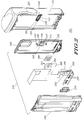
- FIG. 2 is a exploded view in a first orientation of the radio and battery of FIG. 1 when assembled, in accordance with the present invention.
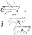
- FIG. 3 is a exploded view of the battery highlighting a second orientation, in accordance with the present invention.
- FIG. 4 is a fragmentary cross-sectional view of the radio and battery assembly of FIG. 2 highlighting the electrical interface, in accordance with the present invention.
- the present invention provides for an electrical interface that interconnects an electrical device with a removable battery.
- the electrical interface includes deflectable cantilever contacts that are preferably located within the battery housing. Each cantilever contact has a portion anchored to a substrate, and a deflectable portion biased against a housing member, which deflectable portion is externally accessible via a slot within the housing member.
- the cantilever contacts are located within a recessed area on an interior surface of the housing member, with a corresponding projection extending externally on the housing member. The external projection facilitates a plug and socket arrangement for mating the battery to the electrical device.
- the substrate is a flexible film substrate that is structurally supported by a backer attached to the housing member.
- FIG. 1 is an exploded perspective view of an assembly 100 of an electrical device 110 and battery 120, in accordance with the present invention.
- the electrical device is a two-way portable radio that houses circuitry and components for communicating over a radio frequency channel.
- the battery is a packaged self-contained unit that is detachable or removable from the radio, such as for recharging purposes.
- the battery package 120 houses energy cells, circuitry, and other components typically included in a rechargeable battery.
- the radio 110 and battery package 120 incorporate an electrical interface or interconnecting structure that comprises mating electrical connectors 125, 215 (see FIG. 2).
- FIG. 2 is an exploded view of the radio and battery assembly 100 shown in a first orientation, in accordance with the present invention.
- FIG. 3 is an exploded view of the battery 120 shown in a second orientation, in accordance with the present invention.
- an electrical interface structure 125, 215 includes a portion 125 on the removable battery 120, an a portion 215 on the electrical device 110.
- a device housing member 211 includes an electrical connector 215 defined by a recessed area with a set of spaced apart fixed contacts 218 projecting within the recessed area.
- the spaced apart contacts 218 have a blade-like form factor that corresponds in shape and size to slots on the electrical connector 125 of the battery package 120.
- a peripheral seal 216 around the electrical connector 215 of the radio 110 provides an environmental seal when interfaced to the battery package 120.
- the removable battery 120 has battery housing members 230, 240, including a main housing member 230 and a battery cover 240, preferably formed from molded plastic material.
- the battery housing members 230, 240 enclose and protect energy cells 335 which provide the primary function of the battery package 120.
- the energy cells 335 may incorporate battery chemistry such as nickel cadmium, nickel metal-hydride, lithium ion, and the like.
- a substrate 250 formed from flexible film material carries battery circuitry 253 and electrical and mechanical components 255, 257 needed to support monitoring, charging, discharging, and the other functions relating to the energy cells 335.
- the circuitry 253 is electrically coupled to the energy cells 335.
- the battery package 120 includes the electrical connector 215 which supports the conveyance of electrical signals between the battery package 120 and the electrical device 110.
- the electrical connector 215 is formed using an electrical interface area 245 defined on a battery housing member 240.
- Movable cantilever contacts 260 electrically coupled to the substrate 250, are biased against the battery housing member 240, preferably by a backer or support member 270, along the electrical interface area 245.
- a gasket 280 interposed between the substrate 250 and battery housing member 240 provides an environmental seal for the connector.
- the electrical interface area 245 is defined on the battery cover 240, such as by molding, and is formed to accommodate the cantilever contacts.
- the electrical interface area 245 is defined by a recessed portion 246 on the interior surface 241 of the battery cover 240 and a corresponding projection or protruded portion 346 on the exterior surface 341 of the battery cover 240.
- the recessed portion 246 has multiple, separate, individualized contact recesses or grooves 247 for individually accommodating each cantilever contact 260, or a portion thereof.
- each contact recess 247 has a form factor corresponding in shape and size to that of the cantilever contact 260.
- each contact recess 247 has a slot 248 extending from the interior surface 241 of the battery cover 240 to the exterior surface 341, such that there are as many slots 248 as there are cantilever contacts 260.
- the cantilever contacts 260 are preferably formed from a single-piece stamped metal part.
- the stamped metal part comprises multiple cantilever arms or fingers joined together by a detachable bridge member 265.
- the cantilever arms 260 are affixed to the flexible film substrate 250 by depositing solder at an anchor portion 261 of each cantilever arm 260.
- the bridge member 265 is then detached to leave multiple cantilever arms 260 individually attached or anchored to the flexible film substrate 250 in proper alignment.
- the cantilever contacts 260 are affixed to the flexible film substrate 250 and the gasket 280 located about each cantilever contact 260.
- the gasket 280 is affixed to the substrate 250, such as by adhesive or the like.
- the substrate 250 is then positioned against the battery housing member 240 such that the cantilever contacts 260 are seated in the corresponding contact recesses 247 within the electrical interface area 245 of the battery housing member 240.
- the backer 270 is mounted or otherwise attached to the battery housing member 240, preferably using mounts 243 located on the battery housing member 240.
- the backer 270 is positioned to provide mechanical support or a biasing force for the cantilever contact members 260.
- portions 262 of the cantilever contacts 260 are individually seated within corresponding recesses 247, and are deflectably biased against the interior surface 241 of the housing member 240 in alignment with corresponding slots 248 in the contact recesses 247.
- the contacts 260 are completely recessed below the exterior surface of the housing member 240.
- the gasket 280 which is positioned about the contacts 260, individually, between the substrate 250 and the interior surface 241 of the battery housing member 240, provides a seal that individually protects each slot 248.
- the preferred embodiment includes a removable battery 120 attached to a portable electrical device 110 with an electrical interface therebetween.
- a connector portion 125 on the removable battery is formed on a battery housing member 240 by a recessed portion along an interior surface, and a corresponding protruded portion on an exterior surface.
- the housing member 240 has slots 248 extending therethrough that expose a corresponding set of cantilever contacts 260.
- Each cantilever contact 260 has a cantilever portion 262 aligned with a corresponding slot, and is deflectably bias against an interior surface of the battery housing member. The contacts are protected by being completely recessed within the housing member 240.
- a recessed area 217 formed within a device housing member 211 includes spaced apart contacts 218 that project within the recessed area 217.
- FIG. 4 is a fragmentary cross-sectional view showing the electrical interface between a radio and battery, in accordance with the present invention.
- the protruded portion 346 of the battery housing member 240 is seated within the recessed area 217 of the device housing member 211 such that the contacts 218 on the device 110 interface with the cantilever contacts 260 on the battery package 120 in a plug and socket arrangement, when the removable battery is mated with the electrical device.
- the present invention provides significant benefits over the prior art. For example, by employing fixed contacts on the host electronic device, the reliability of the electrical interface on the electronic device can be improved. Similarly, a proper electrical connection between the removable battery and the electronic device is assured by employing movable contacts on the battery in an inexpensive manner. Additionally, by positioning the biased cantilever contacts in a plug and socket arrangement, ease of use of the electrical interface is enhanced, and the contacts are protected from damage. These configurations and others are made available by the present invention.
Landscapes
- Chemical & Material Sciences (AREA)
- Chemical Kinetics & Catalysis (AREA)
- Electrochemistry (AREA)
- General Chemical & Material Sciences (AREA)
- Battery Mounting, Suspending (AREA)
Abstract
An electrical interface (125, 215) interconnects an electrical device (110) with a removable battery package (120). The electrical interface (125, 215) includes deflectable cantilever contacts (260) that are preferably located within the battery package (120). Each cantilever contact (260) has a portion (261) anchored to a substrate (250), and a deflectable portion (262) biased against a housing member (240), which deflectable portion (262) is externally accessible via a slot (248) within the housing member (240). Preferably, the cantilever contacts (260) are located within a recessed area (245) on an interior surface (241) of the housing member (240). A corresponding projection (346) extends externally on the housing member (240). The external projection (346) facilitates a plug and socket arrangement for mating the battery (120) to the electrical device (110). The substrate (250) is preferably formed from flexible film material and is structurally supported by a backer (270) attached to the housing member (240).
Description
This invention relates in general to electrical interface connectors,
and more particularly, to a connector interfacing a battery to an
electrical device.
Portable electronic devices, such as two-way radios, typically
include a rechargeable battery that is removably connected to the
electronic device. Ordinarily, the battery is electrically coupled to the
electronic device via an electrical interface that includes a portion on the
electronic device and a portion on the battery. The electrical interface
generally has movable contacts and fixed contacts. The movable contacts
facilitate the establishment of electrical contact between both portions of
the electrical interface by accommodating for variations due to tolerances
and like.
Fixed contacts are typically more inexpensive to incorporate
within a product than are movable contacts. Hence, it is customary to
find fixed contacts employed on the battery to minimize product costs.
Such electrical contacts have been traditionally formed using discrete
contact elements electrically coupled to circuitry within the battery. The
discrete contacts may be affixed directly to a circuit carrying substrate
used in the internal operations of the battery, or may be affixed to a
battery housing member using a rivet, or other type of fastener.
Movable contacts are generally incorporated within that portion of
the electrical interface on the host device. A movable contact tends to
have more parts than a fixed contact, and thus is more expensive to
incorporate into a product. Prior art approaches to movable contacts
include the use of pogo pins, cantilever contacts, springs, and the like.
By incorporating such movable contacts on the electronic device, the
more expensive portion of the electrical interface can be incorporated into
the higher priced unit, i.e., the electronic device. As a user is likely to
purchase several batteries for each electronic device purchased, it is
thought that by incorporating the less expensive component of the
electrical interface on the battery, the overall cost to a customer is
reduced.
It has been observed that a movable contact is much more
susceptible to damage from corrosion, shock, jamming, and the like.
When such contact is damaged, the electronic device must be taken out of
service for repair or replacement of the contact. This deprives the user of
the use of the electronic device, and thus runs contrary to the objective of
reducing overall expense to the user. Fixed contacts, which have no
movable parts, can be formed to be less prone to damage through normal
use.
In an electrical interface, it is desirable to incorporate the
reliability of fixed contacts while providing for the tolerance
accommodation afforded by movable contacts. Therefore, there exists a
need to provide for the incorporation of fixed and movable contacts in an
electrical interface between an electronic device and a removable battery
that is reliable and cost effective.
FIG. 1 is a perspective view of a radio and battery, in accordance
with the present invention.
FIG. 2 is a exploded view in a first orientation of the radio and
battery of FIG. 1 when assembled, in accordance with the present
invention.
FIG. 3 is a exploded view of the battery highlighting a second
orientation, in accordance with the present invention.
FIG. 4 is a fragmentary cross-sectional view of the radio and
battery assembly of FIG. 2 highlighting the electrical interface, in
accordance with the present invention.
The present invention provides for an electrical interface that
interconnects an electrical device with a removable battery. The
electrical interface includes deflectable cantilever contacts that are
preferably located within the battery housing. Each cantilever contact
has a portion anchored to a substrate, and a deflectable portion biased
against a housing member, which deflectable portion is externally
accessible via a slot within the housing member. Preferably, the
cantilever contacts are located within a recessed area on an interior
surface of the housing member, with a corresponding projection
extending externally on the housing member. The external projection
facilitates a plug and socket arrangement for mating the battery to the
electrical device. In the preferred embodiment, the substrate is a flexible
film substrate that is structurally supported by a backer attached to the
housing member.
FIG. 1 is an exploded perspective view of an assembly 100 of an
electrical device 110 and battery 120, in accordance with the present
invention. The electrical device is a two-way portable radio that houses
circuitry and components for communicating over a radio frequency
channel. The battery is a packaged self-contained unit that is detachable
or removable from the radio, such as for recharging purposes. The
battery package 120 houses energy cells, circuitry, and other components
typically included in a rechargeable battery. The radio 110 and battery
package 120 incorporate an electrical interface or interconnecting
structure that comprises mating electrical connectors 125, 215 (see FIG.
2).
FIG. 2 is an exploded view of the radio and battery assembly 100
shown in a first orientation, in accordance with the present invention.
FIG. 3 is an exploded view of the battery 120 shown in a second
orientation, in accordance with the present invention. Referring to
FIGs. 2 and 3, an electrical interface structure 125, 215 includes a
portion 125 on the removable battery 120, an a portion 215 on the electrical
device 110. On the electrical device 110, a device housing member 211
includes an electrical connector 215 defined by a recessed area with a set
of spaced apart fixed contacts 218 projecting within the recessed area. In
the preferred embodiment, the spaced apart contacts 218 have a blade-like
form factor that corresponds in shape and size to slots on the
electrical connector 125 of the battery package 120. A peripheral seal 216
around the electrical connector 215 of the radio 110 provides an
environmental seal when interfaced to the battery package 120.
The removable battery 120 has battery housing members 230, 240,
including a main housing member 230 and a battery cover 240,
preferably formed from molded plastic material. The battery housing
members 230, 240 enclose and protect energy cells 335 which provide the
primary function of the battery package 120. The energy cells 335 may
incorporate battery chemistry such as nickel cadmium, nickel metal-hydride,
lithium ion, and the like. A substrate 250 formed from flexible
film material carries battery circuitry 253 and electrical and mechanical
components 255, 257 needed to support monitoring, charging,
discharging, and the other functions relating to the energy cells 335. The
circuitry 253 is electrically coupled to the energy cells 335.
As noted above, the battery package 120 includes the electrical
connector 215 which supports the conveyance of electrical signals
between the battery package 120 and the electrical device 110. The
electrical connector 215 is formed using an electrical interface area 245
defined on a battery housing member 240. Movable cantilever contacts
260, electrically coupled to the substrate 250, are biased against the
battery housing member 240, preferably by a backer or support member
270, along the electrical interface area 245. A gasket 280 interposed
between the substrate 250 and battery housing member 240 provides an
environmental seal for the connector.
In the preferred embodiment, the electrical interface area 245 is
defined on the battery cover 240, such as by molding, and is formed to
accommodate the cantilever contacts. The electrical interface area 245 is
defined by a recessed portion 246 on the interior surface 241 of the battery
cover 240 and a corresponding projection or protruded portion 346 on the
exterior surface 341 of the battery cover 240. Preferably, the recessed
portion 246 has multiple, separate, individualized contact recesses or
grooves 247 for individually accommodating each cantilever contact 260,
or a portion thereof. Accordingly, each contact recess 247 has a form
factor corresponding in shape and size to that of the cantilever contact
260. Further, each contact recess 247 has a slot 248 extending from the
interior surface 241 of the battery cover 240 to the exterior surface 341,
such that there are as many slots 248 as there are cantilever contacts 260.
The cantilever contacts 260 are preferably formed from a single-piece
stamped metal part. In the preferred embodiment, the stamped
metal part comprises multiple cantilever arms or fingers joined together
by a detachable bridge member 265. The cantilever arms 260 are affixed
to the flexible film substrate 250 by depositing solder at an anchor portion
261 of each cantilever arm 260. The bridge member 265 is then detached
to leave multiple cantilever arms 260 individually attached or anchored
to the flexible film substrate 250 in proper alignment.
To assemble, the cantilever contacts 260 are affixed to the flexible
film substrate 250 and the gasket 280 located about each cantilever
contact 260. The gasket 280 is affixed to the substrate 250, such as by
adhesive or the like. The substrate 250 is then positioned against the
battery housing member 240 such that the cantilever contacts 260 are
seated in the corresponding contact recesses 247 within the electrical
interface area 245 of the battery housing member 240. Once the
cantilever contacts 260 are properly seated within the contact recesses
247, the backer 270 is mounted or otherwise attached to the battery
housing member 240, preferably using mounts 243 located on the battery
housing member 240. Thus, the backer 270 is positioned to provide
mechanical support or a biasing force for the cantilever contact members
260.
When the electrical connector 125 is fully assembled, portions 262
of the cantilever contacts 260 are individually seated within
corresponding recesses 247, and are deflectably biased against the
interior surface 241 of the housing member 240 in alignment with
corresponding slots 248 in the contact recesses 247. The contacts 260 are
completely recessed below the exterior surface of the housing member
240. The gasket 280, which is positioned about the contacts 260,
individually, between the substrate 250 and the interior surface 241 of the
battery housing member 240, provides a seal that individually protects
each slot 248.
In summary, the preferred embodiment includes a removable
battery 120 attached to a portable electrical device 110 with an electrical
interface therebetween. A connector portion 125 on the removable battery
is formed on a battery housing member 240 by a recessed portion along
an interior surface, and a corresponding protruded portion on an
exterior surface. The housing member 240 has slots 248 extending
therethrough that expose a corresponding set of cantilever contacts 260.
Each cantilever contact 260 has a cantilever portion 262 aligned with a
corresponding slot, and is deflectably bias against an interior surface of
the battery housing member. The contacts are protected by being
completely recessed within the housing member 240. On the electrical
device 110, a recessed area 217 formed within a device housing member
211 includes spaced apart contacts 218 that project within the recessed
area 217.
FIG. 4 is a fragmentary cross-sectional view showing the
electrical interface between a radio and battery, in accordance with the
present invention. Here, the protruded portion 346 of the battery housing
member 240 is seated within the recessed area 217 of the device housing
member 211 such that the contacts 218 on the device 110 interface with
the cantilever contacts 260 on the battery package 120 in a plug and socket
arrangement, when the removable battery is mated with the electrical
device.
The present invention provides significant benefits over the prior
art. For example, by employing fixed contacts on the host electronic
device, the reliability of the electrical interface on the electronic device
can be improved. Similarly, a proper electrical connection between the
removable battery and the electronic device is assured by employing
movable contacts on the battery in an inexpensive manner. Additionally,
by positioning the biased cantilever contacts in a plug and socket
arrangement, ease of use of the electrical interface is enhanced, and the
contacts are protected from damage. These configurations and others
are made available by the present invention.
Claims (10)
- An electrical interface structure for a removable battery, comprising:a battery housing member having an interior surface and an exterior surface, and an electrical interface area defined by a recess on the interior surface and a corresponding projection on the exterior surface, the electrical interface area having a plurality of slots extending therethrough; anda plurality of cantilever contacts corresponding to the plurality of slots, each cantilever contact having an anchored portion being fixedly located with respect to the electrical interface area, and having a deflectable cantilever portion seated within the recess and biased against the interior surface of the battery housing member, and externally accessible via a corresponding slot from the exterior surface of the battery housing member, wherein the plurality of cantilever contacts are completely recessed below the exterior surface of the battery housing member.
- The electrical interface structure of claim 1, further comprising a substrate having circuitry thereon, wherein the anchored portion of each cantilever contact is soldered to the substrate and electrically coupled to the circuitry.
- The electrical interface structure of claim 2, wherein the substrate is a flexible film substrate.
- The electrical interface structure of claim 2, further comprising a backer attached to the battery housing member, wherein the substrate is positioned between the backer and the interior surface.
- The electrical interface structure of claim 4, further comprising a gasket positioned between the substrate and the interior surface that provides a seal for the plurality of slots.
- The electrical interface structure of claim 1, wherein the electrical interface area has a groove about each slot that corresponds in shape and size to a cantilever contact, and wherein the plurality of cantilever contacts are each individually seated within a corresponding groove.
- A battery, comprising:a battery cover having an interior surface and an exterior surface, the battery cover having an electrical interface area defined by a recessed portion on the interior surface and a corresponding protruding portion on the exterior surface, the recessed portion having a plurality of contact recesses each having a slot extending therethrough;a flexible film substrate having battery circuitry thereon;a plurality of cantilever contact members affixed to the flexible film substrate, each cantilever contact member being seated within a corresponding contact recess, and having a cantilever portion deflectably biased against the interior surface of the battery cover in alignment with a corresponding slot;a backer mounted to the battery cover and positioned to provide mechanical support for the plurality of cantilever contact members; anda gasket positioned around the plurality of cantilever contact members between the battery cover and the flexible film substrate.
- An apparatus having an electrical interface, comprising:a removable battery, comprising:a battery housing member having an electrical interface area defined by a recessed portion along an interior surface thereof, and a corresponding protruded portion on an exterior surface thereof, the electrical interface area having a plurality of slots extending therethrough; anda plurality of cantilever contacts, each having a cantilever portion aligned with a corresponding slot of the plurality of slots, each cantilever portion being deflectably biased against the interior surface of the battery housing member; anda portable electrical device, comprising:a device housing member having a recessed area formed thereon; anda plurality of spaced apart contacts, projecting within the recessed area;wherein the protruded portion of the battery housing member is seated within the recessed area of the device housing member such that the plurality of spaced apart contacts interface with the plurality of cantilever contacts in a plug and socket arrangement, when the removable battery is mated with the portable electrical device.
- The apparatus of claim 8, wherein the removable battery further comprises a substrate mounted adjacent to the recessed portion of the electrical interface area, and wherein each of the plurality of cantilever contacts has an anchored portion fixedly attached to the substrate.
- A battery, comprising:a battery housing member having an interior surface and an exterior surface, and having a plurality of slots extending therethrough;a plurality of energy cells protected by the battery housing member;a flexible film substrate having circuitry that is electrically coupled to the plurality of energy cells;a plurality of cantilever contacts each having an anchored portion affixed to the flexible film substrate, and a deflectable cantilever portion biased against the interior surface of the battery housing member, and externally accessible via a corresponding slot from the exterior surface of the battery housing member; anda backer attached to the battery housing member and positioned to provide support for the flexible film substrate, and to provide a biasing force for the plurality of cantilever contacts.
Applications Claiming Priority (2)
| Application Number | Priority Date | Filing Date | Title |
|---|---|---|---|
| US679414 | 1984-12-07 | ||
| US08/679,414 US5607791A (en) | 1996-07-08 | 1996-07-08 | Battery interface structure for an electrical device |
Publications (1)
| Publication Number | Publication Date |
|---|---|
| EP0818836A2 true EP0818836A2 (en) | 1998-01-14 |
Family
ID=24726816
Family Applications (1)
| Application Number | Title | Priority Date | Filing Date |
|---|---|---|---|
| EP97111427A Withdrawn EP0818836A2 (en) | 1996-07-08 | 1997-07-07 | Battery interface for an electrical device |
Country Status (6)
| Country | Link |
|---|---|
| US (1) | US5607791A (en) |
| EP (1) | EP0818836A2 (en) |
| CN (1) | CN1170240A (en) |
| AU (1) | AU685732B1 (en) |
| BR (1) | BR9706682A (en) |
| SG (1) | SG67398A1 (en) |
Families Citing this family (29)
| Publication number | Priority date | Publication date | Assignee | Title |
|---|---|---|---|---|
| USD386147S (en) * | 1996-03-25 | 1997-11-11 | Motorola, Inc. | Battery housing for portable communications device |
| US5786106A (en) * | 1996-06-24 | 1998-07-28 | Armani; Shane | Battery pack with interchangeable tag-along supplemental feature cartridge particularly for cellular telephones |
| JP3531090B2 (en) * | 1996-11-07 | 2004-05-24 | 日立マクセル株式会社 | Battery pack |
| US5895729A (en) * | 1997-09-25 | 1999-04-20 | Motorola, Inc. | Battery latch assembly for two-way radio |
| US5909102A (en) * | 1998-01-21 | 1999-06-01 | Motorola, Inc. | Battery connection apparatus employing fixed latching members |
| USD401215S (en) | 1998-02-02 | 1998-11-17 | Motorola, Inc. | Battery housing |
| US5917306A (en) * | 1998-04-27 | 1999-06-29 | Motorola, Inc. | Mnemonic system for indicating battery charge |
| USD407063S (en) | 1998-05-14 | 1999-03-23 | Motorola, Inc. | Battery housing for a cellular telephone |
| US6157545A (en) * | 1998-05-14 | 2000-12-05 | Motorola, Inc. | Battery connection apparatus with end projections |
| TW398677U (en) * | 1998-10-21 | 2000-07-11 | Telepaq Technology Inc | Battery device and joint structure of palm type electronic device |
| US6120932A (en) * | 1998-11-03 | 2000-09-19 | Motorola, Inc. | Battery mounting assembly for a radio |
| US6071640A (en) * | 1998-11-03 | 2000-06-06 | Motorola, Inc. | Battery mounting assembly for a radio |
| JP4110657B2 (en) * | 1999-02-17 | 2008-07-02 | ソニー株式会社 | Battery pack, battery mounting device, power supply device, and electronic device |
| JP3763703B2 (en) * | 1999-06-02 | 2006-04-05 | 株式会社東芝 | Wireless communication device and battery pack and connector |
| JP3609678B2 (en) * | 2000-01-24 | 2005-01-12 | 株式会社バーテックススタンダード | Battery case |
| US6171138B1 (en) * | 2000-01-28 | 2001-01-09 | Motorola, Inc. | Electrical connector for removable components |
| USD435827S1 (en) | 2000-05-19 | 2001-01-02 | Motorola, Inc. | Battery pack for a portable communication device |
| DE60302389T2 (en) * | 2002-06-20 | 2006-07-13 | L'oreal S.A. | Cosmetic and / or dermatological use of a composition containing at least one oxidation-sensitive hydrophilic active agent stabilized with at least one copolymer of maleic anhydride |
| US20040189256A1 (en) * | 2003-02-14 | 2004-09-30 | Alcatel | Reusable state of charge indicator |
| US20040264139A1 (en) * | 2003-06-24 | 2004-12-30 | Nokia Corporation | Process for manufacturing a cover |
| CN2757341Y (en) * | 2004-11-27 | 2006-02-08 | 深圳富泰宏精密工业有限公司 | Cell lid structure |
| US7695853B2 (en) * | 2005-09-28 | 2010-04-13 | Arris Group, Inc. | Frameless multi-size battery compartment with passive capture mechanism |
| US7484981B2 (en) * | 2007-02-01 | 2009-02-03 | Motorola, Inc. | Assembly for sealing an audio connector within an electronic device |
| US7636245B2 (en) * | 2007-06-25 | 2009-12-22 | Novatel Wireless, Inc. | Electronic component cover and arrangement |
| US8168319B2 (en) * | 2008-10-13 | 2012-05-01 | Apple Inc. | Portable computer battery structures |
| USD907576S1 (en) * | 2017-06-06 | 2021-01-12 | Black & Decker Inc. | Electric connector |
| US11075425B2 (en) | 2019-06-28 | 2021-07-27 | Motorola Solutions, Inc. | Battery pack with charger interface |
| US11101505B2 (en) | 2019-06-28 | 2021-08-24 | Motorola Solutions, Inc. | Battery pack interface |
| US11848457B2 (en) | 2021-01-05 | 2023-12-19 | Xentris Wireless, Llc | Small tactical universal battery and methods of interconnection |
Family Cites Families (9)
| Publication number | Priority date | Publication date | Assignee | Title |
|---|---|---|---|---|
| JPS5941973U (en) * | 1982-09-09 | 1984-03-17 | 三洋電機株式会社 | battery pack |
| US5127849A (en) * | 1991-05-28 | 1992-07-07 | Motorola, Inc. | Environmentally sealed battery connector |
| US5225760A (en) * | 1991-11-18 | 1993-07-06 | Leiserson Steven G | Rechargeable power pack |
| US5197889A (en) * | 1992-02-03 | 1993-03-30 | Motorola, Inc. | Electrical contact for battery package or similar device |
| US5238431A (en) * | 1992-02-24 | 1993-08-24 | Motorola, Inc. | Self securing electrical contact assembly |
| US5259786A (en) * | 1992-06-29 | 1993-11-09 | Londa Photo Products Co., Ltd. | Lamp unit battery seat |
| US5421745A (en) * | 1994-01-03 | 1995-06-06 | Motorola, Inc. | Contact array |
| US5403203A (en) * | 1994-05-02 | 1995-04-04 | Motorola, Inc. | Contact array |
| US5466545A (en) * | 1995-01-27 | 1995-11-14 | Fluke Corporation | Compact, shock resistant battery pack |
-
1996
- 1996-07-08 US US08/679,414 patent/US5607791A/en not_active Expired - Lifetime
-
1997
- 1997-06-13 AU AU24869/97A patent/AU685732B1/en not_active Expired
- 1997-06-30 SG SG1997002306A patent/SG67398A1/en unknown
- 1997-07-07 EP EP97111427A patent/EP0818836A2/en not_active Withdrawn
- 1997-07-07 CN CN97114582A patent/CN1170240A/en active Pending
- 1997-07-08 BR BR9706682-6A patent/BR9706682A/en not_active Application Discontinuation
Also Published As
| Publication number | Publication date |
|---|---|
| AU685732B1 (en) | 1998-01-22 |
| CN1170240A (en) | 1998-01-14 |
| SG67398A1 (en) | 1999-09-21 |
| US5607791A (en) | 1997-03-04 |
| BR9706682A (en) | 2000-10-31 |
Similar Documents
| Publication | Publication Date | Title |
|---|---|---|
| US5607791A (en) | Battery interface structure for an electrical device | |
| US7176655B2 (en) | Battery pack with built in communication port | |
| US5472804A (en) | Battery device with integrated circuit substrate packaging | |
| US5459388A (en) | Battery pack with minimum hard wiring connection for portable computer | |
| US5518424A (en) | Connector for a battery | |
| JPS6359226B2 (en) | ||
| US8686689B2 (en) | Battery assembly | |
| EP0545132B1 (en) | Rechargeable power pack | |
| US4611160A (en) | Charging device | |
| KR100572178B1 (en) | Portable electric apparatus including battery therein | |
| JPH05258805A (en) | Grounding block | |
| US7541771B1 (en) | Rechargeable battery and method of assembly | |
| CA2696855A1 (en) | Pass around electrical contacts | |
| US6807067B2 (en) | Battery-Locking mechanism | |
| US5980310A (en) | Power supply unit for portable apparatus and of the type enabling various types of power source to be used, and corresponding portable apparatus | |
| EP4312422B1 (en) | Electronic device housing | |
| US9106082B2 (en) | Connector interface for a charger device | |
| US5403203A (en) | Contact array | |
| CN116412202B (en) | Shaft assemblies and electronic devices | |
| JPH07230842A (en) | Terminal structure for electric equipment and battery pack having this and electronic equipment body | |
| CN117219975A (en) | Battery integrated plate, quick-plug type battery module and female seat | |
| KR200210437Y1 (en) | Charging terminal fixing structure of charger | |
| JP2004095195A (en) | Battery pack and portable electronic device provided with the battery pack | |
| JP2004063436A (en) | Battery for portable electronic equipment | |
| JPH08190905A (en) | Inter-terminal short-circuit preventing structure |
Legal Events
| Date | Code | Title | Description |
|---|---|---|---|
| PUAI | Public reference made under article 153(3) epc to a published international application that has entered the european phase |
Free format text: ORIGINAL CODE: 0009012 |
|
| AK | Designated contracting states |
Kind code of ref document: A2 Designated state(s): AT BE CH DE DK ES FI FR GB GR IE IT LI LU MC NL PT SE |
|
| STAA | Information on the status of an ep patent application or granted ep patent |
Free format text: STATUS: THE APPLICATION IS DEEMED TO BE WITHDRAWN |
|
| 18D | Application deemed to be withdrawn |
Effective date: 20000201 |