EP0818283A1 - Robot - Google Patents
Robot Download PDFInfo
- Publication number
- EP0818283A1 EP0818283A1 EP97304899A EP97304899A EP0818283A1 EP 0818283 A1 EP0818283 A1 EP 0818283A1 EP 97304899 A EP97304899 A EP 97304899A EP 97304899 A EP97304899 A EP 97304899A EP 0818283 A1 EP0818283 A1 EP 0818283A1
- Authority
- EP
- European Patent Office
- Prior art keywords
- component units
- information
- robot apparatus
- electronic parts
- robot
- Prior art date
- Legal status (The legal status is an assumption and is not a legal conclusion. Google has not performed a legal analysis and makes no representation as to the accuracy of the status listed.)
- Withdrawn
Links
Images


Classifications
-
- B—PERFORMING OPERATIONS; TRANSPORTING
- B25—HAND TOOLS; PORTABLE POWER-DRIVEN TOOLS; MANIPULATORS
- B25J—MANIPULATORS; CHAMBERS PROVIDED WITH MANIPULATION DEVICES
- B25J9/00—Programme-controlled manipulators
- B25J9/16—Programme controls
- B25J9/1615—Programme controls characterised by special kind of manipulator, e.g. planar, scara, gantry, cantilever, space, closed chain, passive/active joints and tendon driven manipulators
- B25J9/1617—Cellular, reconfigurable manipulator, e.g. cebot
-
- B—PERFORMING OPERATIONS; TRANSPORTING
- B25—HAND TOOLS; PORTABLE POWER-DRIVEN TOOLS; MANIPULATORS
- B25J—MANIPULATORS; CHAMBERS PROVIDED WITH MANIPULATION DEVICES
- B25J9/00—Programme-controlled manipulators
- B25J9/16—Programme controls
- B25J9/1602—Programme controls characterised by the control system, structure, architecture
- B25J9/161—Hardware, e.g. neural networks, fuzzy logic, interfaces, processor
-
- B—PERFORMING OPERATIONS; TRANSPORTING
- B25—HAND TOOLS; PORTABLE POWER-DRIVEN TOOLS; MANIPULATORS
- B25J—MANIPULATORS; CHAMBERS PROVIDED WITH MANIPULATION DEVICES
- B25J13/00—Controls for manipulators
- B25J13/08—Controls for manipulators by means of sensing devices, e.g. viewing or touching devices
-
- B—PERFORMING OPERATIONS; TRANSPORTING
- B25—HAND TOOLS; PORTABLE POWER-DRIVEN TOOLS; MANIPULATORS
- B25J—MANIPULATORS; CHAMBERS PROVIDED WITH MANIPULATION DEVICES
- B25J19/00—Accessories fitted to manipulators, e.g. for monitoring, for viewing; Safety devices combined with or specially adapted for use in connection with manipulators
- B25J19/02—Sensing devices
-
- B—PERFORMING OPERATIONS; TRANSPORTING
- B25—HAND TOOLS; PORTABLE POWER-DRIVEN TOOLS; MANIPULATORS
- B25J—MANIPULATORS; CHAMBERS PROVIDED WITH MANIPULATION DEVICES
- B25J9/00—Programme-controlled manipulators
- B25J9/16—Programme controls
- B25J9/1615—Programme controls characterised by special kind of manipulator, e.g. planar, scara, gantry, cantilever, space, closed chain, passive/active joints and tendon driven manipulators
-
- G—PHYSICS
- G05—CONTROLLING; REGULATING
- G05B—CONTROL OR REGULATING SYSTEMS IN GENERAL; FUNCTIONAL ELEMENTS OF SUCH SYSTEMS; MONITORING OR TESTING ARRANGEMENTS FOR SUCH SYSTEMS OR ELEMENTS
- G05B19/00—Programme-control systems
- G05B19/02—Programme-control systems electric
- G05B19/18—Numerical control [NC], i.e. automatically operating machines, in particular machine tools, e.g. in a manufacturing environment, so as to execute positioning, movement or co-ordinated operations by means of programme data in numerical form
- G05B19/414—Structure of the control system, e.g. common controller or multiprocessor systems, interface to servo, programmable interface controller
Definitions
- This invention relates to a robot apparatus.
- robot is assembled in a predetermined form using a variety of component units including a body, legs, a head, and so on respectively combined in predetermined states defined by a predetermined correlation of the component units.
- the robot has a control unit having the structure of a microcomputer including a central processing unit (CPU) as well as actuators each having a predetermined degree of freedom and sensors for detecting predetermined physical amounts, and so on, which are placed at their respective predetermined positions.
- the control unit individually controls the operations of the respective actuators based on outputs of the respective sensors, associated programs, and so on, thereby enabling the robot to autonomously run and perform predetermined operations.
- the robot disclosed in Japanese Patent Laid Open No. 245784/93 has the function of setting a unique number to each joint module.
- a control unit can recognize a connection order in which respective joint modules are connected, based on the unique numbers of the joint modules provided thereto through communications between the control unit and the joint modules, and rewrite a control program in an appropriate program based on the recognition results.
- This configuration allows the robot to eliminate a sequence of operations required to create software at the site for assembling the robot (for example, editing, compilation, link, and so on of programs).
- control unit recognizes the connection order for the respective joint modules based on the unique numbers thereof, so that if the connection order for the joint modules is to be changed, new unique numbers must be set again to the respective joint modules corresponding to the change.
- a control unit controlling the operation of the robot can automatically acquire information required to control operations of the component units, such as the shapes of respective component units, positions of parts such as actuators and a variety of sensors, capabilities of these parts, and so on, the control unit can automatically create a corresponding program even when two or more separate groups of component units are combined into a complete assembly, when a new component unit is added or removed or a component unit is repositioned. Therefore, the architecture of a robot in a new form can be facilitated.
- the robot apparatus comprises first storage means for storing shape information for determining shapes of the component units, second storage means for storing motion information required to describe motions of the component units, third storage means for storing characteristic information on electronic parts contained in the component units, and detecting means for detecting coupling states of the respective component units.
- control means can automatically recognize the entire structure and the motion characteristics of the respective component units based on detection results provided by the detecting means.
- each storage means of the respective component units constituting the robot apparatus stores a conversion program for converting first data, represented in a predetermined data format commonly determined beforehand for each function of the electronic parts by a control program used by the control means for controlling the respective component units, into second data represented in a data format used by the respective electronic parts for each function.
- the respective component units can be designed independently of the data format previously determined by the control program.
- the preferred embodiment of this invention provides a robot apparatus which is applicable to a case in which two or more separate groups of arbitrary component units are combined into a complete assembly, and is capable of facilitating the architecture of a robot in a new form.
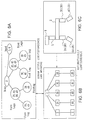
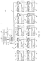
- numeral 1 generally shows a robot according to a first embodiment, in which thigh units 3A to 3D and shin units 4A to 4D are removably mounted in order at four corners, i.e., front, rear, left, and right corners of a body unit 2, and a neck unit 5 and a head unit 6 are removably mounted in order at a central portion of a front end of the body unit 2.
- the body unit 2 contains a central processing unit (CPU) 10 for controlling the operation of the entire robot 1, a serial bus host (SBH) 11 for managing a serial bus described later, a distributor (HUB) 12, and a memory 13.
- the memory 13 stores information on the shape of the body unit 2 such as the width, length, and so on (hereinafter, called “shape information"), information required to describe motions of the body unit 2 such as the mass, rotation moment, center of the axis of rotation, position of the center of gravity, and so on of the body unit 2 (hereinafter, collectively called "motion information"), positional information on respective joining points p1 to p5 of the HUB 12, and so on.
- Each of the component units 3A to 3D, 4A to 4D, 5, 6, except for the body unit 2, contains an HUB 14, electronic parts 15 such as actuators and sensors, and a memory 16.
- Each of the memories 16 of the respective components units 3A to 3D, 4A to 4D, 5, 6 stores shape information and motion information on the corresponding unit of the component units 3A to 3D, 4A to 4D, 5, 6, information on functions and characteristics of respective electronic parts 15 contained in the corresponding unit of the component units 3A to 3D, 4A to 4D, 5, 6 (hereinafter, called the "characteristic information"), and so on.
- the HUB 12 of the body unit 2 is connected to the HUBs 14 of the neck unit 5 and the respective thigh units 3A to 3D through serial buses 17 such as the institute of electrical and electronics engineers, Inc. (IEEE) 1934, the universal serial bus (USB), or the like.
- serial buses 17 such as the institute of electrical and electronics engineers, Inc. (IEEE) 1934, the universal serial bus (USB), or the like.
- the HUBs 14 of the neck unit 5 and the respective thigh units 3A to 3D are respectively connected to the HUB 14 of the head unit 6 and to the HUBs 14 of the corresponding shin units 4A to 4D through the similar serial buses 17.
- the above configuration enables the CPU 10 of the robot 1 to read a variety of information stored in the memories 16 of the respective component units 3A to 3D, 4A to 4D, 5, 6, to send control signals to the actuators disposed in the respective component units 3A to 3D, 4A to 4D, 5, 6, and to receive outputs of sensors disposed in the respective component units 3A to 3D, 4A to 4D, 5, 6, sequentially through the SBH 11, the HUB 12 and the HUBs 14 of the respective component units 3A to 3D, 4A to 4D, 5, 6.
- the CPU 10 can automatically grasp the configuration of the entire robot 1, i.e., which of component units 3A to 3D, 5 are coupled to which portions of the body unit 2, and which of the component units 4A to 4D, 6 are coupled to the component units 3A to 3D, 5, in accordance with the positional information on the respective joining points pl to p5 of the HUB 12 stored in the memory 13 of the body unit 2 and the shape information respectively stored in the memories 16 of the component units 3A to 3D, 4A to 4D, 5, 6 except for the body unit 2.
- the CPU 10 can drive the component units 3A to 3D, 4A to 4D, 5, 6 in desired conditions by driving the actuators disposed in the desired component units 3A to 3D, 4A to 4D, 5, 6 in accordance with the motion information, the characteristic information and so on stored in the memories 16 of the respective component units 3A to 3D, 4A to 4D, 5, 6 except for the body unit 2.
- the CPU can also monitor the current states of the component units 3A to 3D, 4A to 4D, 5, 6 by the outputs of the sensors disposed in the respective component units 3A to 3D, 4A to 4D, 5, 6.
- the memories 16 of the respective component units 3A to 3D, 4A to 4D, 5, 6 store, as the characteristic information on the actuators constituting the corresponding electronic parts 15, for example, information such as the type of each actuator (linear type or rotary type), information describing, for example, "a control signal composed of a pulse signal including ten pulses is required to advance the rotating angle by one degree", and so on.
- the CPU 10 reads information as mentioned above from the memories 16 of the respective component units 3A to 3D, 4A to 4D, 5, 6, and creates a conversion program for converting angle data, for example one degree, into a pulse signal having ten pulses which represents the movement distance of a linear motion in accordance with the read information. Subsequently, the CPU 10 sends a control signal in accordance with the movement distance, obtained by the conversion program, to the component unit 4A to control the operation of the actuator disposed in the component unit 4A.
- the CPU 10 creates a tree with respect to connections of the respective component units 2, 3A to 3D, 4A to 4D, 5, 6 as illustrated in Fig. 3 in accordance with information showing which of the component units 2, 3A to 3D, 4A to 4D, 5, 6 are connected to which component units 2, 3A to 3D, 4A to 4D, 5, 6, and stores the tree as data of a directed graph data structure illustrated in Fig. 4 (hereinafter, the structure is called as the "virtual robot") in the memory 13 of the body unit 2.
- the CPU 10 sequentially reads the shape information on the respective component units 2, 3A to 3D, 4A to 4D, 5, 6 stored in the memories 13 and 16 of the corresponding component units 2, 3A to 3D, 4A to 4D, 5, 6 in a time division manner at predetermined intervals to check the entire structure.
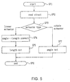
- the CPU 10 starts a control processing for the robot 1 at step SP1, and reads a variety of information from the memory 16 of the thigh unit 3A at step SP2. Then, at the subsequent step SP3, the CPU 10 determines the type of actuator disposed in the thigh unit 3A in accordance with the variety of read information. If it is decided that the actuator of the thigh unit 3A is linear type, the control processing proceeds to step SP4.
- the CPU 10 converts a predetermined angle data (angle) into a movement distance (length) of linear motion, and then sends a control signal corresponding to the movement distance (length) to the actuator of the thigh unit 3A at step SP5, to terminate the control processing for the robot 1 at step SP6.
- step SP3 if the CPU 10 decides at step SP3 that the actuator of the thin unit 3A is rotary type, the control processing proceeds to step SP7, where the CPU 10 sends a control signal corresponding to the predetermined angle data (angle) as it is to the actuator of the thigh unit 3A, to terminate the control processing for the robot 1 at step SP6.
- the CPU 10 may read a variety of data only once when the respective component units 3A to 3D, 4A to 4D, 5, 6 are coupled to the body unit 2. Therefore, the CPU 10 of the robot 1 is configured to subsequently set a movement distance to each of the remaining component units 3A to 3D, 4A to 4D, 5, 6 coupled to the body unit 2 at a predetermined timing.
- the CPU 10 grasps the entire structure of the robot 1 in accordance the shape information, motion information, and characteristic information related to the component units 2, 3A to 3D, 4A to 4D, 5, 6 stored in the memories 13 and 16 of the component units 2, 3A to 3D, 4A to 4D, 5, 6, and controls the operations of the respective component units 2, 3A to 3D, 4A to 4D, 5, 6.
- the CPU 10 can always grasp the entire structure of the robot 1 and control the operations of the respective component units 2, 3A to 3D, 4A to 4D, 5, 6 irrespective of a combination of the component units 2, 3A to 3D, 4A to 4D, 5, 6.
- a designer provides specifying information for a blue print robot (a robot having a data structure designed by the designer) 18 illustrated in Fig. 6A.
- the specifying information are that respective parts of the blue print robot 18 having certain functions and composed of one or more component units are designated as a head, forelegs, and so on, and where the respective sites are positioned.
- the blue print robot of Fig. 6A means that the component units 5, 6 of the physical robot (real robot) 1 of Fig.
- the designer corresponds the blue print robot to the virtual robot to communicate information between the blue print robot and the actual component units only using the blue print robot.
- the respective component units of the robot can be interactively moved using the graphical user interface (GUI) on the personal computer.
- GUI graphical user interface
- the virtual robot in the system may be transferred to the personal computer.
- the personal computer may be provided with predetermined design drawings showing how respective component units are coupled (actually, the design drawings have the same data structure as that of the virtual robot), such that the personal computer compares in shape currently used component units sent thereto from the robot with the respective component units on the design drawings to inform the user that erroneous component units are used, the coupling order is not correct, or the like, for example, by flashing corresponding positions on a robot image graphically represented on the display of the personal computer.
- the user use a combination of certain parts as function parts.
- the former method is a method of interactively generating motions of the function parts.
- the latter method is a method of using motion data which is prepared for using the previously corresponding sites as the corresponding functions. Further, as described later, a device driver corresponding to functional information can be stored in the respective memories.
- the respective component units 2, 3A to 3D, 4A to 4D, 5, 6 contain the memories 13 and 16 which store shape information, motion information and so on of the corresponding component units 2, 3A to 3D, 4A to 4D, 5, 6, and the CPU 10 can read a variety of information respectively stored in the memories 13 and 16 of the component units 2, 3A to 3D, 4A to 4D, 5, 6 as required, so that the CPU 10 can grasp the entire structure of the robot 1 irrespective of coupling states of the component units 2, 3A to 3D, 4A to 4D, 5, 6, and control the operations of the respective component units 2, 3A to 3D, 4A to 4D, 5, 6.
- a robot apparatus which can be applied to a configuration including two or more separate groups of arbitrary component units combined into a complete assembly, and thus facilitate the architecture of a robot in a new form.
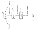
- an automaton 30 is a higher rank program for giving the goal for the action of the robot based on outputs of sensors disposed in respective component units
- a MoNet 31 is a lower rank program having a graph structure as illustrated in Fig. 8 for restricting transitions of the attitude of the robot.
- An output from the MoNet 31 is time series of Nodes (attitude, state) ST1 to ST4 of the graph structure, and Edges (programs for changing the attitude) E1 to E6 between the respective Nodes ST1 to ST4 store programs for controlling actuators (hereinafter, called the "motors") of respective component units such as a head and legs.
- a motor command generator 32 (MCG) (Fig. 7) uses the programs stored in the Edges E1 to E6 to generate commands to the respective motors in the entire robot and outputs the commands to the associated motors.
- the second embodiment is intended to achieve complicated operations of the robot by a combination of coordinated operations of the respective component units and independent operations of the respective component units.
- the respective component units such as the head, hands, legs and so on of the robot as well as the entire robot are provided with the autonomy as mentioned above such that the respective component units can independently operate based on outputs of sensors disposed in the respective component units and also operate in response to instructions given thereto from the control unit which collectively governs the respective component units.
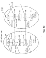
- Fig. 9 illustrates the configuration of a robot 40 according to the second embodiment which has two hand blocks, two leg blocks and a head block.
- the body unit 2 is physically connected to a head block composed of the neck unit 5 and the head unit 6 and to four leg blocks composed of the thigh units 3A to 3D and the shin units 4A to 4D.
- a body block 41 is logically connected to a hand block 42, a leg block 43 and a head block 44, and the hand block 42 and the leg block 43 are further connected to left and right component blocks 42A, 42B, 43A, 43B, respectively.
- Fig. 10 illustrates functions of the respective component blocks 42, 43, 42A, 42B, 43A, 43B illustrated in Fig. 9.
- the component blocks 42, 43 are each composed of an automaton 30A, MoNet 31A and MCG 32A
- the component blocks 42A, 42B, 43A, 43B are each composed of an automaton 30B, MoNet 31B and MCG 32B.
- first Comps 50A and 51A and second Comps 50B and 51B are provided for selecting one of the two groups by making them contend with each other.
- an autonomous robot implies a problem as to how to treat reflective actions and actions taken in accordance with time consuming plans.
- a tree structure for a logical structure of the robot 40 having meaning as illustrated in Fig. 9 is advantageous in giving an answer to the problem.
- lower rank branches Light Hand, Left Hand, and so on
- upper rank branches Hands, Body, and so on
- a task of converting a trajectory of a motion of a hand in a three-dimensional space into angles of respective joints (inverse kinematic calculation) or the like requires a large amount of calculations for a branch at a higher rank.
- component units corresponding to hands and legs can make a quick response.
- each component unit can be provided with autonomy in a robot assembled by combining two or more separate groups of arbitrary component units. Consequently, the robot can achieve complicated motions by executing simpler programs.
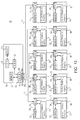
- the CPU 10 reads a data structure representing shape information, motion information and characteristic information from the memories 16 of respective component units 3A to 3D, 4A to 4D, 5, 6 as the first embodiment.
- the third embodiment treats such a conversion program as an object, and previously stores the conversion program in memories 61 (Fig. 11) of the respective component units 3A to 3D, 4A to 4D, 5, 6.
- the memories 61 of the respective component units 3A to 3D, 4A to 4D, 5, 6 store a data structure representing shape information, motion information and characteristic information on the associated component units 3A to 3D, 4A to 4D, 5, 6 as well as an interface program as an information reading program for reading the data structure and a conversion program as objects (since an interface program is called a "method" in object-oriented environment, the interface program in this embodiment is hereinafter called the "method” likewise).
- a method for reading the data structure is provided for reading the data structure from the objects read from the memories 61 of the respective component units 3A to 3D, 4A to 4D, 5, 6, and this method is commonly used in all the component units 3A to 3D, 4A to 4D, 5, 6.
- a method is defined for each information, such as a method for reading shape information, a method for reading motion information, and a method for reading characteristic information, such that the data structure can be stored in an arbitrary order in the associated memory 61.
- the conversion program converts predetermined data (For example, for a function of an electronic part 15 serving as an actuator, a data format applied to an actuator for any component unit has been determined to be given as angle data, by way of example) represented in a predetermined data format commonly determined beforehand for each function of associated electronic parts 15 by a program used by a CPU 63 contained in a body unit 62 for controlling the respective component units 2, 3A to 3D, 4A to 4D, 5, 6 (hereinafter, called the "control program") into data represented by a data format (for example, a length) used by each electronic part 15 for each function.
- a method is set to each function of parts such as an actuator constituting the electronic parts 15 (i.e., each function of the electronic parts 15).
- the number of parts constituting the electronic parts 15 in each of the component units 3A to 3D, 4A to 4D, 5, 6 i.e., the number of functions of the electronic parts 15
- there is one method constituting the conversion program there is one method constituting the conversion program. If a plurality of parts constitute the electronic parts 15 in each of the component units 3A to 3D, 4A to 4D, 5, 6, there are the plurality of methods constituting the conversion program, corresponding to the number of parts.
- the electronic part 15 is an actuator to which a rotating angle can be specified for its motion
- the user is not conscious of whether the used actuator is an actuator of rotary type as a geared motor or an actuator of linear type as an ultrasonic linear motor which is incorporated in a mechanical system by certain techniques to rotate a joint.
- a rotating angle is set using a method for specifying the rotating angle (for example, "void set Angle(Angle Data & angle) ;"
- data for example, rotating angle data
- data represented in a predetermined data format applied to the actuator previously determined by the control program is converted into data (proper value) represented in a data format used by the actuator, i.e., the electronic part 15, and then transferred on a serial bus 17 as a data series for the electronic parts.
- the CPU 63 When the respective component units 3A to 3D, 4A to 4D, 5, 6 are coupled to the body unit 62, the CPU 63 reads the objects from the memories 61 of the respective component units 3A to 3D, 4A to 4D, 5, 6 through a system bus 17, and stores the objects in a memory 65 contained in the body unit 62 so as to control the operations of the respective component units 3A to 3D, 4A to 4D, 5, 6 based on the objects corresponding to the respective component units 3A to 3D, 4A to 4D, 5, 6.
- the CPU 63 starts the control processing for the robot 1 at step SP1, reads objects from the memory 61 of the component unit 3A at step SP2, and subsequently converts at step SP3 predetermined angle data as first data represented in a predetermined format given by the control program into data (proper value) as second data represented in a data format used by the actuator in the electronic parts 15 based on the conversion program included in the read objects, irrespective of whether the actuator in the electronic parts 15 of the component unit 3A is a linear type or a rotary type.
- the CPU 63 sends a control signal corresponding to the proper value to the component unit 3A through the system bus 17 at step SP4 to control the operation of the component unit 3A, and terminates the control processing for the robot 1 at step SP5.
- the CPU 63 needs to read the objects only once at the time the component units 3A, 3B, 3C, 3D, 4A, 4B, 4C, 4D, 5, 6 are coupled to the body unit 62. Subsequently, predetermined angles are set to actuators in the respective component units 3A, 3B, 3C, 3D, 4A, 4B, 4C, 4D, 5, 6 coupled to the body unit 62 at predetermined timing.
- the first data represented in a predetermined format determined beforehand for each function of the electronic parts 15 by the control program is converted into the second data represented in a data format used by the electronic parts 15 of the component units 3A to 3D, 4A to 4D, 5, 6 for each function, so that the respective component units 3A to 3D, 4A to 4D, 5, 6 can be designed independently of the data format determined beforehand by the control program.
- the designer may design the component units 3A to 3D, 4A to 4D, 5, 6 such that data convenient to the component units 3A to 3D, 4A to 4D, 5, 6 can be used therefor, and store a conversion program for converting first data into such convenient data in the memory of the each component unit, thereby eliminating the need of creating a different program for each component unit, when the designer designs each of the component unit, so that complicated and time-consuming works are largely reduced during the designing of the component units.
- a data structure representing shape information, motion information and characteristic information, a method commonly used for the electronic parts 15 in all of the component units 3A to 3D, 4A to 4D, 5, 6 for reading the data structure from objects, and a conversion program for converting first data represented in a data format commonly determined beforehand for each function of the electronic parts 15 by the control program into second data represented in a data format used by the electronic parts 15 for each function are stored in the memory 61 of each of the component units 3A to 3D, 4A to 4D, 5, 6 as objects, such that the CPU 63 reads the objects from the memories 61 of the component units 3A to 3D, 4A to 4D, 5, 6 at the time the component units 3A to 3D, 4A to 4D, 5, 6 are coupled to the body unit 62, whereby the component units 3A to 3D, 4A to 4D, 5, 6 can be designed independently of the data format determined beforehand by the control program.
- the robot 1 which can significantly improve the degree of freedom
- a data structure can be stored in each memory 61 in an arbitrary order.
- the component units 2, 3A to 3D, 4A to 4D, 5, 6 are internally provided with the memories 13 and 16 which store shape information, motion information, characteristic information, and so on of the associated component units 2, 3A to 3D, 4A to 4D, 5, 6, however, the present invention is not limited thereto and as illustrated in Fig. 13 in which parts corresponding to those in Fig.
- memories 71 and 72 of respective component units 2, 3A to 3D, 4A to 4D, 5, 6 store a manufacturer number and a part number of the associated component units 2, 3A to 3D, 4A to 4D, 5, 6, and a body unit 74 is provided therein with a memory 73 (or any other storage means) for storing shape information, motion information, characteristic information, and so on of the component units 2, 3A to 3D, 4A to 4D, 5, 6 corresponding to the manufacturer numbers and the part numbers thereof, such that a CPU 10 detects a tree structure of each of the component units 2, 3A to 3D, 4A to 4D, 5, 6 in accordance the information stored in the memory 73.
- the memories 13 and 16 is applied as storage means for storing shape information, motion information, characteristic information, and so on on the respective component units 2, 3A to 3D, 4A to 4D, 5, 6, however, the present invention is not limited to thereto and a variety of different storage means can be applied instead. In this case, one or all of the shape information, motion information and characteristic information on the component units 2, 3A to 3D, 4A to 4D, 5, 6 can be stored in separate storage means.
- the shape information on the component units 2, 3A to 3D, 4A to 4D, 5, 6 stored in the associated component units 2, 3A to 3D, 4A to 4D, 5, 6 is width, length, or the like
- the present invention is not limited thereto and the shape information can include, when assuming a predetermined coordinate system and coordinate axes for any of the component units 2, 3A to 3D, 4A to 4D, 5, 6, a coupling position of the component unit 2, 3A to 3D, 4A to 4D, 5, 6 with one or more of the remaining component units 2, 3A to 3D, 4A to 4D, 5, 6, the position of the center of rotation and the direction of rotation on the aforementioned coordinate system when the component unit 2, 3A to 3D, 4A to 4D, 5 or 6 is rotated, and the position of the origin of a linear motion on the aforementioned coordinate system when the component unit 2, 3A to 3D, 4A to 4D, 5 or 6 is linearly moved.
- the detecting means for detecting coupling states of the component units 2, 3A to 3D, 4A to 4D, 5, 6 is composed of the CPU 10, the memories 13 and 16, the serial bus 17 and so on, however, the present invention is not limited thereto and a variety of different configuration can be applied.
- the CPU 10 sequentially reads shape information on the component units 2, 3A to 3D, 4A to 4D, 5, 6 stored in the memories 13 and 16 of the respective component units 2, 3A to 3D, 4A to 4D, 5, 6 at predetermined intervals in a time-division manner, to check the entire structure of the robot 1, however, the present invention is not limited thereto and the CPU 10 can detect coupling states among the component units 2, 3A to 3D, 4A to 4D, 5, 6 when the coupling states change.
- a robot apparatus composed of one or a plurality of component units can comprise logical means for logically coupling the component units in a tree structure to configure one or more sites; goal generating means for forcing each of the sites to generate a predetermined first action goal independently of each other; input means for inputting a second action goal outputted from a higher rank of the tree structure; selecting means for selecting the first or second action goal from the first and second action goals; output means for outputting the first or second action goal selected by the selecting means to a lower rank in the tree structure; generating means for generating an action at a current time from the first or second action goal selected by the selecting means; and operation instruction generating means for generating an operation instruction from the action at the current time to an actuator for driving a corresponding component unit.
- data structure representing shape information, motion information and characteristic information, a method for reading the data structure from objects, and a conversion program for converting predetermined data represented in a predetermined format beforehand determined by a control program into data represented in a data format used by the electronic parts 15 of the respective component units 3A to 3D, 4A to 4D, 5, 6 for each function are previously stored in the memories 61 of the respective component units 3A to 3D, 4A to 4D, 5, 6 as objects.
- the present invention is not limited thereto and necessary electronic parts 15 such as actuators, sensors and so on are contained in the body unit 62, a data structure representing characteristic information on the electronic parts 15 in addition to shape information, motion information and positional information, a method for reading the data structure from objects, a conversion program for converting predetermined data represented in a predetermined data format beforehand determined by a control program into data represented in a data format used by the electronic parts 15 of the body unit 2 for each function can be previously stored in the memory 13 as objects, such that the CPU 10 reads the objects from the memory 13 to control the operation of the body unit 62 based on the read objects.
- the CPU 63 is configured to read the objects from the memory 13 of the body unit 62, when the robot 1 is powered on, or when one of, a plurality of, or all of the component units 3A, 3B, 3C, 3D, 4A, 4B, 4C, 4D, 5, 6 are replaced with component units of different type.
- a data structure representing shape information, motion information and characteristic information, a method for reading the data structure, and a conversion program for converting first data represented in a predetermined data format commonly determined beforehand for each function by a control program into second data represented in a data format used by the respective electronic parts 15 for each function thereof are stored in the memories 61 of the respective component units 3A to 3D, 4A to 4D, 5, 6 as objects, however, the present invention is not limited thereto and the aforementioned data structure, the method and the conversion program can be stored in the memories 61 of the respective component units 3A to 3D, 4A to 4D, 5, 6 without treating them as objects.
- the storage means of the respective component units constituting a robot apparatus stores a conversion program for converting first data represented in predetermined data format commonly determined beforehand for each function by a control program used by the control means for controlling the respective component units into second data represented in a data format used by the respective electronic parts for each function, so that the respective component units can be designed independently of the data format determined beforehand by the control program. It is therefore possible to realize a robot apparatus which can significantly improve the degree of freedom in designing the respective component units.
Priority Applications (2)
| Application Number | Priority Date | Filing Date | Title |
|---|---|---|---|
| EP99203993A EP0993914B1 (fr) | 1996-07-08 | 1997-07-04 | Robot |
| EP99203994A EP0993915B1 (fr) | 1996-07-08 | 1997-07-04 | Robot |
Applications Claiming Priority (4)
| Application Number | Priority Date | Filing Date | Title |
|---|---|---|---|
| JP196989/96 | 1996-07-08 | ||
| JP19698996 | 1996-07-08 | ||
| JP19040/97 | 1997-01-31 | ||
| JP01904097A JP3446933B2 (ja) | 1996-07-08 | 1997-01-31 | ロボツト装置及びその制御方法 |
Related Child Applications (2)
| Application Number | Title | Priority Date | Filing Date |
|---|---|---|---|
| EP99203993A Division EP0993914B1 (fr) | 1996-07-08 | 1997-07-04 | Robot |
| EP99203994A Division EP0993915B1 (fr) | 1996-07-08 | 1997-07-04 | Robot |
Publications (1)
| Publication Number | Publication Date |
|---|---|
| EP0818283A1 true EP0818283A1 (fr) | 1998-01-14 |
Family
ID=26355834
Family Applications (3)
| Application Number | Title | Priority Date | Filing Date |
|---|---|---|---|
| EP97304899A Withdrawn EP0818283A1 (fr) | 1996-07-08 | 1997-07-04 | Robot |
| EP99203993A Expired - Lifetime EP0993914B1 (fr) | 1996-07-08 | 1997-07-04 | Robot |
| EP99203994A Expired - Lifetime EP0993915B1 (fr) | 1996-07-08 | 1997-07-04 | Robot |
Family Applications After (2)
| Application Number | Title | Priority Date | Filing Date |
|---|---|---|---|
| EP99203993A Expired - Lifetime EP0993914B1 (fr) | 1996-07-08 | 1997-07-04 | Robot |
| EP99203994A Expired - Lifetime EP0993915B1 (fr) | 1996-07-08 | 1997-07-04 | Robot |
Country Status (4)
| Country | Link |
|---|---|
| US (1) | US5963712A (fr) |
| EP (3) | EP0818283A1 (fr) |
| KR (1) | KR100495963B1 (fr) |
| DE (2) | DE69724832T2 (fr) |
Cited By (20)
| Publication number | Priority date | Publication date | Assignee | Title |
|---|---|---|---|---|
| EP1072365A1 (fr) * | 1999-07-28 | 2001-01-31 | Yamaha Hatsudoki Kabushiki Kaisha | Système de contrôle pour machine modulaire |
| EP1106310A1 (fr) * | 1999-11-30 | 2001-06-13 | STMicroelectronics S.r.l. | Circuit électronique de commande de déplacement par une architecture cellulaire floue |
| EP1120205A1 (fr) * | 1999-01-25 | 2001-08-01 | Sony Corporation | Robot |
| US6462498B1 (en) | 2000-05-09 | 2002-10-08 | Andrew J. Filo | Self-stabilizing walking apparatus that is capable of being reprogrammed or puppeteered |
| US6705917B2 (en) | 2000-12-15 | 2004-03-16 | Andrew S. Filo | Self-phase synchronized walking and turning quadruped apparatus |
| EP0924034A3 (fr) * | 1997-12-22 | 2004-04-14 | Sony Corporation | Robots et procédés de commande des robots |
| EP1415771A2 (fr) | 2002-10-30 | 2004-05-06 | Fanuc Ltd | Robot comprenant une partie interchangeable munie d'une mémoire où sont stockées les caractéristiques de cette partie |
| US8002716B2 (en) | 2007-05-07 | 2011-08-23 | Raytheon Company | Method for manufacturing a complex structure |
| US8002365B2 (en) | 2006-11-13 | 2011-08-23 | Raytheon Company | Conformable track assembly for a robotic crawler |
| US8042630B2 (en) | 2006-11-13 | 2011-10-25 | Raytheon Company | Serpentine robotic crawler |
| US8185241B2 (en) | 2006-11-13 | 2012-05-22 | Raytheon Company | Tracked robotic crawler having a moveable arm |
| WO2012084664A1 (fr) * | 2010-12-22 | 2012-06-28 | BSH Bosch und Siemens Hausgeräte GmbH | Obtention d'un codage d'une variante |
| US8317555B2 (en) | 2009-06-11 | 2012-11-27 | Raytheon Company | Amphibious robotic crawler |
| US8392036B2 (en) | 2009-01-08 | 2013-03-05 | Raytheon Company | Point and go navigation system and method |
| US8393422B1 (en) | 2012-05-25 | 2013-03-12 | Raytheon Company | Serpentine robotic crawler |
| US8571711B2 (en) | 2007-07-10 | 2013-10-29 | Raytheon Company | Modular robotic crawler |
| US8935014B2 (en) | 2009-06-11 | 2015-01-13 | Sarcos, Lc | Method and system for deploying a surveillance network |
| US9031698B2 (en) | 2012-10-31 | 2015-05-12 | Sarcos Lc | Serpentine robotic crawler |
| US9409292B2 (en) | 2013-09-13 | 2016-08-09 | Sarcos Lc | Serpentine robotic crawler for performing dexterous operations |
| US9566711B2 (en) | 2014-03-04 | 2017-02-14 | Sarcos Lc | Coordinated robotic control |
Families Citing this family (38)
| Publication number | Priority date | Publication date | Assignee | Title |
|---|---|---|---|---|
| US6751526B2 (en) | 1997-08-22 | 2004-06-15 | Sony Corporation | Method for describing robot structure and part of robot |
| WO2000032361A1 (fr) * | 1998-11-30 | 2000-06-08 | Sony Corporation | Robot, procede de commande de robot et support d'enregistrement de programme |
| KR20010041969A (ko) | 1999-01-18 | 2001-05-25 | 이데이 노부유끼 | 로봇 장치, 로봇 장치의 본체 유닛 및 로봇 장치의 결합유닛 |
| KR20010053322A (ko) | 1999-04-30 | 2001-06-25 | 이데이 노부유끼 | 전자 페트 시스템, 네트워크 시스템, 로봇, 및 기억 매체 |
| WO2000067961A1 (fr) * | 1999-05-10 | 2000-11-16 | Sony Corporation | Robot et commande de ce robot |
| US6519506B2 (en) | 1999-05-10 | 2003-02-11 | Sony Corporation | Robot and control method for controlling the robot's emotions |
| WO2000067959A1 (fr) * | 1999-05-10 | 2000-11-16 | Sony Corporation | Dispositif robotique et procede de commande associe |
| AU781515B2 (en) * | 1999-10-29 | 2005-05-26 | Samsonite Ip Holdings S.A.R.L. | Direct forming of non-textile fabric elements from thermoplastic pellets or the like |
| US7807247B1 (en) * | 1999-10-29 | 2010-10-05 | Bromley Robert L | Flexlock with headed pintle and conical buttressing |
| US7442107B1 (en) | 1999-11-02 | 2008-10-28 | Sega Toys Ltd. | Electronic toy, control method thereof, and storage medium |
| US6684127B2 (en) * | 2000-02-14 | 2004-01-27 | Sony Corporation | Method of controlling behaviors of pet robots |
| CN1372506A (zh) * | 2000-03-24 | 2002-10-02 | 索尼公司 | 机器人设备行为决定方法和机器人设备 |
| JP2001277166A (ja) * | 2000-03-31 | 2001-10-09 | Sony Corp | ロボット及びロボットの行動決定方法 |
| JP2002036158A (ja) * | 2000-07-27 | 2002-02-05 | Yamaha Motor Co Ltd | 自律機能を有する電子機器 |
| US7120517B2 (en) * | 2001-01-02 | 2006-10-10 | Avraham Friedman | Integration assisting system and method |
| WO2002069609A2 (fr) * | 2001-02-27 | 2002-09-06 | Anthrotronix, Inc. | Appareil robotise et systeme de telecommunications sans fil |
| EP1254688B1 (fr) * | 2001-04-30 | 2006-03-29 | Sony France S.A. | robot autonome |
| AU2002357040A1 (en) * | 2001-11-28 | 2003-06-10 | Evolution Robotics, Inc. | Sensor and actuator abstraction and aggregation in a hardware abstraction layer for a robot |
| KR100578342B1 (ko) * | 2003-01-03 | 2006-05-11 | 주식회사 메가로보틱스 | 인공지능형 로봇완구 및 그 제어방법 |
| US8175747B2 (en) * | 2003-12-22 | 2012-05-08 | Irobou Co., Ltd. | Joinable robot component for robot toy, modifiable robot toy using the joinable robot components, and control method thereof |
| KR100617936B1 (ko) * | 2005-03-31 | 2006-08-30 | 주식회사 유진로봇 | 로봇의 제어를 위한 각종 드라이버의 모듈화와 모듈화되어진 장치를 이용한 제어기 구현방법 및 그에 따른제어기 |
| FI119136B (fi) * | 2006-06-06 | 2008-07-31 | Abb Oy | Sähkökäyttöjärjestelmä |
| US7606411B2 (en) * | 2006-10-05 | 2009-10-20 | The United States Of America As Represented By The Secretary Of The Navy | Robotic gesture recognition system |
| CN101631651B (zh) * | 2007-01-12 | 2013-07-24 | 汉斯乔格·巴尔特斯 | 用于产生机器人的方法和系统 |
| WO2009038772A2 (fr) | 2007-09-20 | 2009-03-26 | Evolution Robotics | Dispositif de commande intelligent et transférable |
| US20100017026A1 (en) * | 2008-07-21 | 2010-01-21 | Honeywell International Inc. | Robotic system with simulation and mission partitions |
| US8414350B2 (en) * | 2008-08-18 | 2013-04-09 | Rehco, Llc | Figure with controlled motorized movements |
| JP5418506B2 (ja) * | 2009-02-10 | 2014-02-19 | 富士通株式会社 | ライブラリ装置及びライブラリ装置の制御方法 |
| DE102009054112A1 (de) * | 2009-11-20 | 2011-05-26 | Kuka Roboter Gmbh | Verfahren und Vorrichtung zur Planung und/oder Steuerung einer Roboterapplikation |
| US9358687B2 (en) * | 2013-01-24 | 2016-06-07 | Mohammad Reza Emami | System, method and computer program for autonomously emulating robot manipulators of continuously-varying configurations |
| US10105845B1 (en) * | 2016-02-05 | 2018-10-23 | Boston Dynamics, Inc. | Modular robot system |
| US10987804B2 (en) * | 2016-10-19 | 2021-04-27 | Fuji Xerox Co., Ltd. | Robot device and non-transitory computer readable medium |
| CN108284442B (zh) * | 2017-01-24 | 2021-01-26 | 中国北方车辆研究所 | 一种基于模糊神经网络的机械臂柔性关节控制方法 |
| US10265844B2 (en) * | 2017-03-24 | 2019-04-23 | International Business Machines Corporation | Creating assembly plans based on triggering events |
| JP2019042856A (ja) * | 2017-08-31 | 2019-03-22 | 川崎重工業株式会社 | ロボット及びロボットの組立性確認方法 |
| US11267121B2 (en) * | 2018-02-13 | 2022-03-08 | Casio Computer Co., Ltd. | Conversation output system, conversation output method, and non-transitory recording medium |
| CN112130483A (zh) * | 2020-08-27 | 2020-12-25 | 深圳市优必选科技股份有限公司 | 一种机器人的控制方法及机器人 |
| US11926048B2 (en) * | 2021-05-26 | 2024-03-12 | Amazon Technologies, Inc. | Modular robotic linkages |
Citations (7)
| Publication number | Priority date | Publication date | Assignee | Title |
|---|---|---|---|---|
| JPS63241613A (ja) * | 1987-03-30 | 1988-10-06 | Hitachi Ltd | モジユ−ル型マニピユレ−タの制御装置 |
| JPH01296350A (ja) * | 1988-05-25 | 1989-11-29 | Hitachi Ltd | 知識格納方式 |
| WO1990006546A1 (fr) * | 1988-12-09 | 1990-06-14 | Schonlau William J | Systeme robotique modulaire |
| EP0400624A2 (fr) * | 1989-05-31 | 1990-12-05 | Kabushiki Kaisha Toshiba | Appareil de commande de distribution |
| JPH054181A (ja) * | 1991-06-24 | 1993-01-14 | Toshiba Corp | ロボツト制御装置 |
| JPH05245784A (ja) * | 1991-11-25 | 1993-09-24 | Toshiba Corp | マニピュレータ装置 |
| US5428713A (en) * | 1991-11-25 | 1995-06-27 | Kabushiki Kaisha Toshiba | Compound module type manipulator apparatus |
Family Cites Families (8)
| Publication number | Priority date | Publication date | Assignee | Title |
|---|---|---|---|---|
| US4467436A (en) * | 1981-10-26 | 1984-08-21 | United States Robots, Inc. | Robot arm controller with common bus memory |
| US4488241A (en) * | 1981-12-08 | 1984-12-11 | Zymark Corporation | Robot system with interchangeable hands |
| US4833626A (en) * | 1986-10-14 | 1989-05-23 | International Business Machines Corporation | Optimizing printer throughput |
| US4964062A (en) * | 1988-02-16 | 1990-10-16 | Ubhayakar Shivadev K | Robotic arm systems |
| JP3167404B2 (ja) * | 1992-02-26 | 2001-05-21 | 本田技研工業株式会社 | ロボットの関節駆動制御装置 |
| US5523662A (en) * | 1994-05-02 | 1996-06-04 | Engineering Services, Inc. | Modular, expandable and reconfigurable robot |
| JP2001038663A (ja) * | 1999-07-28 | 2001-02-13 | Yamaha Motor Co Ltd | マシンの制御システム |
| AU2001259610A1 (en) * | 2000-05-09 | 2001-11-20 | Hasbro, Inc. | Self-stabilizing walking apparatus that is capable of being reprogrammed or puppeteered |
-
1997
- 1997-07-03 US US08/887,624 patent/US5963712A/en not_active Expired - Lifetime
- 1997-07-04 DE DE69724832T patent/DE69724832T2/de not_active Expired - Lifetime
- 1997-07-04 EP EP97304899A patent/EP0818283A1/fr not_active Withdrawn
- 1997-07-04 EP EP99203993A patent/EP0993914B1/fr not_active Expired - Lifetime
- 1997-07-04 DE DE69717680T patent/DE69717680T2/de not_active Expired - Lifetime
- 1997-07-04 EP EP99203994A patent/EP0993915B1/fr not_active Expired - Lifetime
- 1997-07-08 KR KR1019970032435A patent/KR100495963B1/ko not_active IP Right Cessation
Patent Citations (7)
| Publication number | Priority date | Publication date | Assignee | Title |
|---|---|---|---|---|
| JPS63241613A (ja) * | 1987-03-30 | 1988-10-06 | Hitachi Ltd | モジユ−ル型マニピユレ−タの制御装置 |
| JPH01296350A (ja) * | 1988-05-25 | 1989-11-29 | Hitachi Ltd | 知識格納方式 |
| WO1990006546A1 (fr) * | 1988-12-09 | 1990-06-14 | Schonlau William J | Systeme robotique modulaire |
| EP0400624A2 (fr) * | 1989-05-31 | 1990-12-05 | Kabushiki Kaisha Toshiba | Appareil de commande de distribution |
| JPH054181A (ja) * | 1991-06-24 | 1993-01-14 | Toshiba Corp | ロボツト制御装置 |
| JPH05245784A (ja) * | 1991-11-25 | 1993-09-24 | Toshiba Corp | マニピュレータ装置 |
| US5428713A (en) * | 1991-11-25 | 1995-06-27 | Kabushiki Kaisha Toshiba | Compound module type manipulator apparatus |
Non-Patent Citations (4)
| Title |
|---|
| PATENT ABSTRACTS OF JAPAN vol. 013, no. 047 (P - 822) 3 February 1989 (1989-02-03) * |
| PATENT ABSTRACTS OF JAPAN vol. 014, no. 084 (P - 1007) 16 February 1990 (1990-02-16) * |
| PATENT ABSTRACTS OF JAPAN vol. 017, no. 268 (M - 1416) 25 May 1993 (1993-05-25) * |
| PATENT ABSTRACTS OF JAPAN vol. 017, no. 705 (M - 1534) 22 December 1993 (1993-12-22) * |
Cited By (26)
| Publication number | Priority date | Publication date | Assignee | Title |
|---|---|---|---|---|
| EP0924034A3 (fr) * | 1997-12-22 | 2004-04-14 | Sony Corporation | Robots et procédés de commande des robots |
| EP1120205A1 (fr) * | 1999-01-25 | 2001-08-01 | Sony Corporation | Robot |
| EP1120205A4 (fr) * | 1999-01-25 | 2004-05-12 | Sony Corp | Robot |
| EP1072365A1 (fr) * | 1999-07-28 | 2001-01-31 | Yamaha Hatsudoki Kabushiki Kaisha | Système de contrôle pour machine modulaire |
| US6708068B1 (en) | 1999-07-28 | 2004-03-16 | Yamaha Hatsudoki Kabushiki Kaisha | Machine comprised of main module and intercommunicating replaceable modules |
| EP1106310A1 (fr) * | 1999-11-30 | 2001-06-13 | STMicroelectronics S.r.l. | Circuit électronique de commande de déplacement par une architecture cellulaire floue |
| US6728687B2 (en) | 1999-11-30 | 2004-04-27 | Stmicroelectronics S.R.L. | Electronic circuit for controlling a movement by a fuzzy cellular architecture |
| US6462498B1 (en) | 2000-05-09 | 2002-10-08 | Andrew J. Filo | Self-stabilizing walking apparatus that is capable of being reprogrammed or puppeteered |
| US6705917B2 (en) | 2000-12-15 | 2004-03-16 | Andrew S. Filo | Self-phase synchronized walking and turning quadruped apparatus |
| EP1415771A2 (fr) | 2002-10-30 | 2004-05-06 | Fanuc Ltd | Robot comprenant une partie interchangeable munie d'une mémoire où sont stockées les caractéristiques de cette partie |
| EP1415771A3 (fr) * | 2002-10-30 | 2007-12-19 | Fanuc Ltd | Robot comprenant une partie interchangeable munie d'une mémoire où sont stockées les caractéristiques de cette partie |
| US8002365B2 (en) | 2006-11-13 | 2011-08-23 | Raytheon Company | Conformable track assembly for a robotic crawler |
| US8042630B2 (en) | 2006-11-13 | 2011-10-25 | Raytheon Company | Serpentine robotic crawler |
| US8185241B2 (en) | 2006-11-13 | 2012-05-22 | Raytheon Company | Tracked robotic crawler having a moveable arm |
| US8205695B2 (en) | 2006-11-13 | 2012-06-26 | Raytheon Company | Conformable track assembly for a robotic crawler |
| US8434208B2 (en) | 2007-05-07 | 2013-05-07 | Raytheon Company | Two-dimensional layout for use in a complex structure |
| US8002716B2 (en) | 2007-05-07 | 2011-08-23 | Raytheon Company | Method for manufacturing a complex structure |
| US8571711B2 (en) | 2007-07-10 | 2013-10-29 | Raytheon Company | Modular robotic crawler |
| US8392036B2 (en) | 2009-01-08 | 2013-03-05 | Raytheon Company | Point and go navigation system and method |
| US8317555B2 (en) | 2009-06-11 | 2012-11-27 | Raytheon Company | Amphibious robotic crawler |
| US8935014B2 (en) | 2009-06-11 | 2015-01-13 | Sarcos, Lc | Method and system for deploying a surveillance network |
| WO2012084664A1 (fr) * | 2010-12-22 | 2012-06-28 | BSH Bosch und Siemens Hausgeräte GmbH | Obtention d'un codage d'une variante |
| US8393422B1 (en) | 2012-05-25 | 2013-03-12 | Raytheon Company | Serpentine robotic crawler |
| US9031698B2 (en) | 2012-10-31 | 2015-05-12 | Sarcos Lc | Serpentine robotic crawler |
| US9409292B2 (en) | 2013-09-13 | 2016-08-09 | Sarcos Lc | Serpentine robotic crawler for performing dexterous operations |
| US9566711B2 (en) | 2014-03-04 | 2017-02-14 | Sarcos Lc | Coordinated robotic control |
Also Published As
| Publication number | Publication date |
|---|---|
| DE69724832T2 (de) | 2004-08-12 |
| EP0993914A2 (fr) | 2000-04-19 |
| DE69717680D1 (de) | 2003-01-16 |
| DE69724832D1 (de) | 2003-10-16 |
| EP0993914B1 (fr) | 2003-09-10 |
| KR980008471A (ko) | 1998-04-30 |
| DE69717680T2 (de) | 2003-09-18 |
| EP0993914A3 (fr) | 2000-06-07 |
| US5963712A (en) | 1999-10-05 |
| EP0993915A3 (fr) | 2000-06-07 |
| EP0993915A2 (fr) | 2000-04-19 |
| KR100495963B1 (ko) | 2005-09-30 |
| EP0993915B1 (fr) | 2002-12-04 |
Similar Documents
| Publication | Publication Date | Title |
|---|---|---|
| US5963712A (en) | Selectively configurable robot apparatus | |
| US5511147A (en) | Graphical interface for robot | |
| ES2566354T3 (es) | Dispositivo y procedimiento para la generación asistida por ordenador de una línea de manipuladores | |
| Kucuk et al. | An off‐line robot simulation toolbox | |
| EP0923011B1 (fr) | Système robotique et procédé d'entraínement pour robot | |
| US5038089A (en) | Synchronized computational architecture for generalized bilateral control of robot arms | |
| US20110153297A1 (en) | Device and method for the computer-assisted generation of a manipulator path | |
| Anderson | Autonomous, teleoperated, and shared control of robot systems | |
| JP3446933B2 (ja) | ロボツト装置及びその制御方法 | |
| Chen et al. | Automatic modeling for modular reconfigurable robotic systems: Theory and practice | |
| AbuQassem | Simulation and Interfacing of 5 DOF Educational Robot Arm | |
| CN108500967A (zh) | 控制方法、模块式关节机器人和存储介质 | |
| JP2003266347A (ja) | 脚式移動ロボットのための動作編集装置及び動作編集方法 | |
| CN108673486A (zh) | 模块式关节机器人、控制方法和存储介质 | |
| EP0899639B1 (fr) | Méthode pour décrire la structure d'un robot et une partie d'un robot | |
| Pirron et al. | MPERL: Hardware and Software Co-design for Robotic Manipulators© | |
| Klee | Development of a motor speed control system using matlab and simulink, implemented with a digital signal processor | |
| Balaram et al. | An Ada run-time control architecture for telerobots | |
| Milway et al. | Interfacing transputer links to external devices | |
| Spanos et al. | Multisegment large space robot: Concept and design | |
| Escalera et al. | Base molecule design and simulation of modular robot RobMAT | |
| Frazao et al. | Agent-based software architecture for multi-robot teams | |
| Juan et al. | Planning automatic assembly for robots (PAAR) | |
| Campbell | The cornell robot system design report | |
| Paul | The early stages of robotics |
Legal Events
| Date | Code | Title | Description |
|---|---|---|---|
| PUAI | Public reference made under article 153(3) epc to a published international application that has entered the european phase |
Free format text: ORIGINAL CODE: 0009012 |
|
| AK | Designated contracting states |
Kind code of ref document: A1 Designated state(s): DE FR GB |
|
| 17P | Request for examination filed |
Effective date: 19980604 |
|
| AKX | Designation fees paid |
Free format text: DE FR GB |
|
| RBV | Designated contracting states (corrected) |
Designated state(s): DE FR GB |
|
| 17Q | First examination report despatched |
Effective date: 19990507 |
|
| STAA | Information on the status of an ep patent application or granted ep patent |
Free format text: STATUS: THE APPLICATION IS DEEMED TO BE WITHDRAWN |
|
| 18D | Application deemed to be withdrawn |
Effective date: 20010626 |