EP0817972B1 - Bearing assembly having integrated speed sensor - Google Patents
Bearing assembly having integrated speed sensor Download PDFInfo
- Publication number
- EP0817972B1 EP0817972B1 EP96910567A EP96910567A EP0817972B1 EP 0817972 B1 EP0817972 B1 EP 0817972B1 EP 96910567 A EP96910567 A EP 96910567A EP 96910567 A EP96910567 A EP 96910567A EP 0817972 B1 EP0817972 B1 EP 0817972B1
- Authority
- EP
- European Patent Office
- Prior art keywords
- set forth
- bearing apparatus
- shaft
- bearing
- sensor device
- Prior art date
- Legal status (The legal status is an assumption and is not a legal conclusion. Google has not performed a legal analysis and makes no representation as to the accuracy of the status listed.)
- Revoked
Links
- 238000001514 detection method Methods 0.000 claims description 28
- 230000001939 inductive effect Effects 0.000 claims description 7
- 230000003287 optical effect Effects 0.000 claims description 5
- 238000000034 method Methods 0.000 description 7
- 238000010276 construction Methods 0.000 description 6
- 230000004048 modification Effects 0.000 description 4
- 238000012986 modification Methods 0.000 description 4
- 230000000712 assembly Effects 0.000 description 3
- 238000000429 assembly Methods 0.000 description 3
- 230000035699 permeability Effects 0.000 description 3
- 238000011109 contamination Methods 0.000 description 2
- 238000012423 maintenance Methods 0.000 description 2
- 239000000463 material Substances 0.000 description 2
- 230000013011 mating Effects 0.000 description 2
- 238000005259 measurement Methods 0.000 description 2
- 238000009825 accumulation Methods 0.000 description 1
- 230000004323 axial length Effects 0.000 description 1
- 230000008901 benefit Effects 0.000 description 1
- 230000008859 change Effects 0.000 description 1
- 230000000295 complement effect Effects 0.000 description 1
- 239000004020 conductor Substances 0.000 description 1
- 230000000694 effects Effects 0.000 description 1
- 239000002184 metal Substances 0.000 description 1
- 230000000063 preceeding effect Effects 0.000 description 1
- 230000009467 reduction Effects 0.000 description 1
- 230000004044 response Effects 0.000 description 1
- 230000000007 visual effect Effects 0.000 description 1
Images

Classifications
-
- G—PHYSICS
- G01—MEASURING; TESTING
- G01P—MEASURING LINEAR OR ANGULAR SPEED, ACCELERATION, DECELERATION, OR SHOCK; INDICATING PRESENCE, ABSENCE, OR DIRECTION, OF MOVEMENT
- G01P3/00—Measuring linear or angular speed; Measuring differences of linear or angular speeds
- G01P3/42—Devices characterised by the use of electric or magnetic means
- G01P3/44—Devices characterised by the use of electric or magnetic means for measuring angular speed
- G01P3/443—Devices characterised by the use of electric or magnetic means for measuring angular speed mounted in bearings
-
- F—MECHANICAL ENGINEERING; LIGHTING; HEATING; WEAPONS; BLASTING
- F16—ENGINEERING ELEMENTS AND UNITS; GENERAL MEASURES FOR PRODUCING AND MAINTAINING EFFECTIVE FUNCTIONING OF MACHINES OR INSTALLATIONS; THERMAL INSULATION IN GENERAL
- F16C—SHAFTS; FLEXIBLE SHAFTS; ELEMENTS OR CRANKSHAFT MECHANISMS; ROTARY BODIES OTHER THAN GEARING ELEMENTS; BEARINGS
- F16C35/00—Rigid support of bearing units; Housings, e.g. caps, covers
- F16C35/04—Rigid support of bearing units; Housings, e.g. caps, covers in the case of ball or roller bearings
- F16C35/042—Housings for rolling element bearings for rotary movement
- F16C35/047—Housings for rolling element bearings for rotary movement with a base plate substantially parallel to the axis of rotation, e.g. horizontally mounted pillow blocks
-
- F—MECHANICAL ENGINEERING; LIGHTING; HEATING; WEAPONS; BLASTING
- F16—ENGINEERING ELEMENTS AND UNITS; GENERAL MEASURES FOR PRODUCING AND MAINTAINING EFFECTIVE FUNCTIONING OF MACHINES OR INSTALLATIONS; THERMAL INSULATION IN GENERAL
- F16C—SHAFTS; FLEXIBLE SHAFTS; ELEMENTS OR CRANKSHAFT MECHANISMS; ROTARY BODIES OTHER THAN GEARING ELEMENTS; BEARINGS
- F16C35/00—Rigid support of bearing units; Housings, e.g. caps, covers
- F16C35/04—Rigid support of bearing units; Housings, e.g. caps, covers in the case of ball or roller bearings
- F16C35/06—Mounting or dismounting of ball or roller bearings; Fixing them onto shaft or in housing
- F16C35/07—Fixing them on the shaft or housing with interposition of an element
- F16C35/073—Fixing them on the shaft or housing with interposition of an element between shaft and inner race ring
-
- F—MECHANICAL ENGINEERING; LIGHTING; HEATING; WEAPONS; BLASTING
- F16—ENGINEERING ELEMENTS AND UNITS; GENERAL MEASURES FOR PRODUCING AND MAINTAINING EFFECTIVE FUNCTIONING OF MACHINES OR INSTALLATIONS; THERMAL INSULATION IN GENERAL
- F16C—SHAFTS; FLEXIBLE SHAFTS; ELEMENTS OR CRANKSHAFT MECHANISMS; ROTARY BODIES OTHER THAN GEARING ELEMENTS; BEARINGS
- F16C41/00—Other accessories, e.g. devices integrated in the bearing not relating to the bearing function as such
- F16C41/007—Encoders, e.g. parts with a plurality of alternating magnetic poles
-
- G—PHYSICS
- G01—MEASURING; TESTING
- G01P—MEASURING LINEAR OR ANGULAR SPEED, ACCELERATION, DECELERATION, OR SHOCK; INDICATING PRESENCE, ABSENCE, OR DIRECTION, OF MOVEMENT
- G01P1/00—Details of instruments
- G01P1/02—Housings
- G01P1/026—Housings for speed measuring devices, e.g. pulse generator
-
- F—MECHANICAL ENGINEERING; LIGHTING; HEATING; WEAPONS; BLASTING
- F16—ENGINEERING ELEMENTS AND UNITS; GENERAL MEASURES FOR PRODUCING AND MAINTAINING EFFECTIVE FUNCTIONING OF MACHINES OR INSTALLATIONS; THERMAL INSULATION IN GENERAL
- F16C—SHAFTS; FLEXIBLE SHAFTS; ELEMENTS OR CRANKSHAFT MECHANISMS; ROTARY BODIES OTHER THAN GEARING ELEMENTS; BEARINGS
- F16C19/00—Bearings with rolling contact, for exclusively rotary movement
- F16C19/22—Bearings with rolling contact, for exclusively rotary movement with bearing rollers essentially of the same size in one or more circular rows, e.g. needle bearings
- F16C19/34—Bearings with rolling contact, for exclusively rotary movement with bearing rollers essentially of the same size in one or more circular rows, e.g. needle bearings for both radial and axial load
- F16C19/38—Bearings with rolling contact, for exclusively rotary movement with bearing rollers essentially of the same size in one or more circular rows, e.g. needle bearings for both radial and axial load with two or more rows of rollers
-
- F—MECHANICAL ENGINEERING; LIGHTING; HEATING; WEAPONS; BLASTING
- F16—ENGINEERING ELEMENTS AND UNITS; GENERAL MEASURES FOR PRODUCING AND MAINTAINING EFFECTIVE FUNCTIONING OF MACHINES OR INSTALLATIONS; THERMAL INSULATION IN GENERAL
- F16C—SHAFTS; FLEXIBLE SHAFTS; ELEMENTS OR CRANKSHAFT MECHANISMS; ROTARY BODIES OTHER THAN GEARING ELEMENTS; BEARINGS
- F16C2226/00—Joining parts; Fastening; Assembling or mounting parts
- F16C2226/10—Force connections, e.g. clamping
- F16C2226/16—Force connections, e.g. clamping by wedge action, e.g. by tapered or conical parts
-
- F—MECHANICAL ENGINEERING; LIGHTING; HEATING; WEAPONS; BLASTING
- F16—ENGINEERING ELEMENTS AND UNITS; GENERAL MEASURES FOR PRODUCING AND MAINTAINING EFFECTIVE FUNCTIONING OF MACHINES OR INSTALLATIONS; THERMAL INSULATION IN GENERAL
- F16C—SHAFTS; FLEXIBLE SHAFTS; ELEMENTS OR CRANKSHAFT MECHANISMS; ROTARY BODIES OTHER THAN GEARING ELEMENTS; BEARINGS
- F16C2226/00—Joining parts; Fastening; Assembling or mounting parts
- F16C2226/50—Positive connections
- F16C2226/60—Positive connections with threaded parts, e.g. bolt and nut connections
-
- F—MECHANICAL ENGINEERING; LIGHTING; HEATING; WEAPONS; BLASTING
- F16—ENGINEERING ELEMENTS AND UNITS; GENERAL MEASURES FOR PRODUCING AND MAINTAINING EFFECTIVE FUNCTIONING OF MACHINES OR INSTALLATIONS; THERMAL INSULATION IN GENERAL
- F16C—SHAFTS; FLEXIBLE SHAFTS; ELEMENTS OR CRANKSHAFT MECHANISMS; ROTARY BODIES OTHER THAN GEARING ELEMENTS; BEARINGS
- F16C23/00—Bearings for exclusively rotary movement adjustable for aligning or positioning
- F16C23/06—Ball or roller bearings
- F16C23/08—Ball or roller bearings self-adjusting
- F16C23/082—Ball or roller bearings self-adjusting by means of at least one substantially spherical surface
- F16C23/086—Ball or roller bearings self-adjusting by means of at least one substantially spherical surface forming a track for rolling elements
-
- F—MECHANICAL ENGINEERING; LIGHTING; HEATING; WEAPONS; BLASTING
- F16—ENGINEERING ELEMENTS AND UNITS; GENERAL MEASURES FOR PRODUCING AND MAINTAINING EFFECTIVE FUNCTIONING OF MACHINES OR INSTALLATIONS; THERMAL INSULATION IN GENERAL
- F16C—SHAFTS; FLEXIBLE SHAFTS; ELEMENTS OR CRANKSHAFT MECHANISMS; ROTARY BODIES OTHER THAN GEARING ELEMENTS; BEARINGS
- F16C2326/00—Articles relating to transporting
- F16C2326/58—Conveyor systems, e.g. rollers or bearings therefor
Definitions
- the present invention relates generally to the art of bearing assemblies for facilitating rotation of a shaft. More particularly, the invention relates to a bearing assembly having an integrated speed sensor for detecting a rotational rate of the shaft.
- Bearing assemblies are often constructed including their own housing, such as a pillow block or a flange housing.
- the housing facilitates placement of the bearing at a desired location for supporting a rotatable shaft.
- suitable means are provided for effecting operative securement of the bearing assembly to the shaft.
- securement means may be utilized for this purpose, including set screws, eccentric collar, clamping collar and tapered adapter sleeve configurations.
- such self-contained bearings may be used to rotatably support pulleys in a conveyor system. At least one such pulley will generally be driven by a prime mover, such as an electric motor. Other pulleys are undriven, thereby functioning simply as idlers to guide and support the conveyor belt.
- a prime mover such as an electric motor.
- Other pulleys are undriven, thereby functioning simply as idlers to guide and support the conveyor belt.
- slippage may occur between the conveyor belt and one or more of the pulleys. Occurrence of such slippage, particularly at the drive pulley, can result in significant wear being imparted to the conveyor belt. Worn belts must be replaced, leading to replacement cost and loss of productivity during maintenance. In other situations, belts may tear, which can cause undesirable accumulation of product fed by a preceeding conveyor.
- Belt slippage or a torn belt may both be evidenced by a reduction in speed of an undriven pulley rotated by the belt.
- One technique for detecting this speed change utilizes a disk attached to an end of the pulley shaft.
- the disk is configured having multiple slots or multiple magnets spaced apart about its circumference.
- a speed sensor is mounted to a bracket such that it will be proximate to the rotating disk. An output signal of the speed sensor is indicative of the rate at which the shaft, and thus the pulley, is rotating.
- EP 0 617 206 discloses a bearing assembly where a bearing is axially positioned by a nut.
- a plurality of exciter teeth are circumferentially disposed about the outer surface of the annulary member and extend perpendicularly therefrom.
- a sensing device extends radially in from an engine outer housing, which is not shown, and uses the exciter teeth to measure the engine rotational speed. It is not disclosed how and where the sensing device is mounted at the engine outer housing.
- the sensing device has to have a very long shaft to reach the exciter teeth on the nut. By this long shaft, the sensing device can easily be damaged.
- Another disadvantage is that the sensing device is vibrating when the engine is running and therefore an exact measuring of the rotational speed is not possible.
- the present invention recognizes and addresses the foregoing disadvantages, and others, of prior art constructions and methods. Accordingly, it is an object of the present invention to provide an improved bearing assembly.
- an improved bearing apparatus including a bearing housing having a bearing assembly contained therein.
- the bearing assembly includes respective first and second ring members capable of relative rotation, with the first ring member being secured to the shaft during operation.
- a sensor device is mounted to the housing for detecting the rotational rate of the shaft.
- the bearing assembly further includes a detection element affixed during operation with respect to the first ring member.
- the sensor device is preferably operative to detect a rate of rotation of the shaft by detecting a rate of rotation of the detection element.
- the sensor may be configured as an inductive sensor operative to sense variations in its inductance produced during rotation of the detection element.
- Other sensors may also be used in some embodiments, however, such as magnetic pick-up sensors or optical sensors.
- the bearing assembly may be secured to the shaft utilizing a clamping arrangement having a nut or a clamping collar.
- the nut or collar may be adapted to facilitate detection of the rotational rate of the shaft.
- an element already utilized in the bearing assembly for securement may also effectively function as the detection element.
- the nut or collar may be constructed in a number of configurations.
- the nut or collar may be configured defining a plurality of slots spaced apart about its circumference.
- a plurality of holes may be defined at spaced apart locations about the circumference of the nut or collar, with or without respective plug members located therein.
- the sensor device may read off an attached sprocket element.
- the sensor device extends through a wall of the housing. A portion of the sensor on the outside of the housing may be protected by a shroud element.
- the sensor device itself may be situated in various sensing directions, such as axially or radially disposed with respect to the detection element.
- the shaft terminates at an interior location of the housing.
- the housing may include a covered end portion for shielding an end of the shaft.
- the end portion may be removable or may be formed integral with the bearing housing.
- a method of detecting a rate of rotation of a shaft supported by at least one bearing assembly comprises the step of providing the bearing assembly with an annular detection element affixed with respect to an inner ring member of the bearing.
- a sensor device is provided which is capable of detecting a rate of rotation of the annular detection element.
- Another step involves situating the sensor device in a fixed location proximate to the bearing such that a sensing direction thereof is oriented toward the annular detection element.
- a regular variation in a predetermined characteristic caused by rotation of the annular detection element is then detected with the sensor device.
- the rate of rotation of the shaft is determined from the regular variation in the predetermined characteristic.
- the sensor device utilized in the method may be an inductive sensor.
- the regular variation in the predetermined characteristic would be a regular variation in an inductance of the sensor produced by rotation of the annular detection element.
- Other sensors, such as magnetic pick-up sensors and optical sensors, may also be utilized.
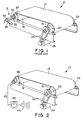
- FIG. 1 illustrates a conveyor system 10 utilizing a prior art arrangement 12 for determining shaft speed.
- conveyor 10 includes an endless conveyor belt 14 extending about a pair of pulleys respectively indicated at 16 and 18. Shaft portions extending from each axial end of pulley 16 are supported by bearing assemblies 20 and 22. Similarly, pulley 18 is supported by a bearing assembly 24 and a similar bearing assembly at its opposite axial end (not shown). Pulley 16 is driven by an electric motor 26 via a drive belt 28.
- Arrangement 12 includes a disk 30 mounted to an end of shaft 32, which is a continuation of the shaft supported by bearing assembly 24. As described above, disk 30 is configured having multiple slots or multiple magnets spaced apart about its circumference.
- a sensor 34 such as an inductive sensor, is mounted in a sensing direction toward and proximate to disk 30. As shown, sensor 34 is maintained in this position by a mounting bracket 36.
- shaft 32 also requires bearing assembly 24 to have a housing which is open throughout. As a result, a housing which is closed on one side cannot be used. Closed housings are desirable in many situations, however, to enclose the rotating end of the pulley shaft such that leakage and contamination are reduced.
- FIG. 2 illustrates a modification of conveyor system 10 which overcomes the noted disadvantages of the prior art.
- bearing assembly 24 has been replaced with a bearing assembly 38 constructed in accordance with the present invention.
- Other conventional aspects of conveyor system 10 remain unchanged and are indicated by the same reference number.
- bearing assembly 38 integrally includes means for determining the rotational rate of the pulley shaft.
- An appropriate indicator device 40 such as has been utilized with the prior art, may be provided to give an indication of the rotational rate of such shaft.
- indicator device 40 will be electrically connected to bearing assembly 38 utilizing an appropriate conductor, such as line 42.
- a visual indicator or an audible device such as speaker 44, may also be included to provide a warning when certain events take place.
- indicator device 40 is preferably configured to provide a warning if the rotational rate of the monitored pulley falls below the drive speed by more than a predetermined threshold.
- speaker 44 may sound an alarm if the speed of pulley 18 is more than six (6) percent or other suitable threshold below the speed of pulley 16.
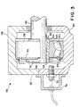
- bearing assembly 38 is operatively connected to a rotatable shaft 46 which terminates inside of a bearing housing.
- the bearing housing in this case includes a top portion, or cap 48, situated on a base 50.
- an end wall 52 is formed in the housing such that the rotating end of shaft 46 will be unexposed.
- bearing assembly 38 Internal to housing 48, bearing assembly 38 includes a bearing inner ring member 54 secured to shaft 46 in a suitable manner.
- Inner ring member 54 defines an inner raceway about its outer circumferential surface, as shown.
- An outer ring member 56 is further provided having an outer raceway situated in opposition to the inner raceway.
- a plurality of bearing elements, such as roller bearings 58 and 60, are disposed between the inner raceway and the outer raceway to facilitate relative rotation between ring members 54 and 56. While roller bearings are illustrated, it should be appreciated that other suitable types of bearing elements, such as ball bearings, may also be utilized for this purpose.
- tapered adapter 62 includes a tapered portion 64 having a first end of a lesser diameter extending to a second end of a greater diameter. Portion 64 thus defines a tapered outer surface between the first end and the second end thereof. Tapered adapter 62 further defines a radial opening, or slot, extending along its entire axial length.
- inner ring member 54 defines a tapered inner surface generally complementary to the tapered outer surface of portion 64.
- the radial opening of adapter 62 allows it to contract about shaft 46 when the tapered outer surface of portion 64 and the tapered inner surface of inner ring member 54 are moved axially together. As a result, inner ring member 54 is positively clamped to shaft 46.
- the relative axial movement between adapter 62 and inner ring member 54 may be accomplished utilizing a nut 66 engaging a threaded portion 68 of tapered adapter 62.
- portion 68 is located adjacent the lesser diameter end of tapered portion 64.
- a washer 70 may be interposed between nut 66 and inner ring member 64, as shown.
- bearing assembly 38 includes a sensor device 72 for detecting the rotational rate of shaft 46.
- sensor device 72 for detecting the rotational rate of shaft 46.
- the exemplary construction illustrated utilizes a "magnetic-type” sensor, which refers herein to a sensor which detects speed based on variations in a magnetic phenomenon, such as an inductive sensor or a magnetic pick-up sensor.
- An inductive sensor typically functions by detecting changes in the inductance of a sensor coil caused by variations in adjacent metallic bodies.
- a suitable inductive sensor for this purpose is Model No. 871T, manufactured by Allen-Bradley.
- a magnetic pick-up sensor typically functions to generate an EMF in response to a time-varying magnetic field.
- sensor device 7.2 is threaded into a bore formed in end wall 52. It will be appreciated that the compact configuration of sensor device 72 and its placement make it much less susceptible to damage than the prior art configuration shown in Figure 1. However, a shroud element 74 may be attached to housing 48 and situated about sensor device 72 to provide additional protection from damage.
- sensor device 72 may determine the rotational rate of shaft 46 by determining the rotational rate of inner ring member 54.
- sensor device 72 is oriented to detect variations in its inductance caused by rotation of nut 66, which rotates with inner ring member 54.
- nut 66 has been modified to facilitate speed detection. Specifically, nut 66 defines a series of slots 76 spaced about its outer circumferential surface. As will be appreciated, slots 76 define regions having a different magnetic permeability than adjacent regions of nut 66. Thus, as nut 66 rotates, this varying permeability may be detected at sensor device 72. The frequency of these variations is indicative of rotational speed.
- sensor device 72 is shown oriented in a sensing direction substantially parallel to the axis of shaft 46. It should be appreciated, however, that sensor device 72 may be situated in various other orientations which may be preferred in some applications.
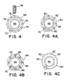
- Figure 4 illustrates a sensor device 78 which is oriented radially with respect to shaft 46.
- Figures 4A through 4C illustrate other nut embodiments which may also be utilized to produce predetermined magnetic variations.
- Figure 4A illustrates an alternative nut 80 having a series of holes 82 defined about its circumference. Such holes function to produce magnetic variations in a manner similar to slots 76 of nut 66.
- a nut 84 having a plurality of plug elements 86 attached thereto at spaced apart locations about its circumference.
- plug elements may be configured of a material having to have either greater or lesser magnetic permeability than adjacent portions of nut 84.
- plug elements 86 may be constructed of a material very similar to nut 84. In such embodiments, plug elements 86 should be either protrude from or be sunken into nut 84 to present a varying metal thickness to the sensor device.
- Elements 86 may be threaded elements, such as screws, engaging threaded holes defined in nut 84.
- Figure 4C illustrates a nut having a sprocket element 90 fixedly attached thereto.
- sprocket element 90 defines a number of protruding teeth 92 separated by adjacent concave regions. This construction also produces predetermined magnetic variations as the nut is rotated.
- the bearing housing in this case includes a removable end cap 94 attached by bolts 96 or other suitable means of effecting such attachment.
- a removable end cap such as end cap 94 will often be desirable to facilitate maintenance of the interior components of the bearing assembly.
- Figure 5 further illustrates the use of an optical sensor device 98 instead of a magnetic-type sensor as described above.
- a nut 100 is provided having a slotted disc 102 attached thereto.
- Sensor device 98 includes a light source which directs incident light upon slotted disc 102, as shown by the arrow.
- the slots in disc 102 cause varying degrees of reflection back toward sensor device 98 during shaft rotation. Such reflection is sensed by a photodetector within sensor device 98. The frequency of the variations in reflection is thus indicative of shaft speed.
- embodiments of the present invention may be constructed wherein means other than a tapered adapter are utilized to clamp the inner ring member to a shaft.
- embodiments may be constructed utilizing eccentric collar or set screw clamping arrangements.
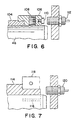
- Figure 6 illustrates an embodiment utilizing an eccentric collar clamping arrangement.
- the inner ring member in this arrangement includes an extension portion 104 defining an outer circumferential groove near its axial end.
- This groove will preferably be slightly eccentric with respect to the shaft bore of the inner ring member.
- a clamping collar 106 is provided having a portion adapted for mating with the outer circumferential groove of portion 104. This mating portion will also be slightly eccentric. Rotation of collar 106 with respect to portion 104 thus causes a clamping of the bearing assembly to shaft 46.
- a set screw 108 may be provided to secure the clamping positions of collar 106 and portion 104. The operation of such an eccentric collar configuration is well known to those of ordinary skill in the art.
- collar 106 may be modified in a manner similar to nut 66 of Figure 3.
- collar 106 includes a plurality of plug elements such as plug element 110, spaced apart its circumference. Rotation of shaft 46 thus presents a variation in magnetic characteristics which may be detected by sensor 112 in the manner described above.
- FIG. 7 other embodiments may be constructed utilizing a clamping arrangement in which the inner ring member includes an extension portion defining 114 a plurality of axial slots 116 spaced apart about its circumference to form a plurality of clamping fingers.
- a clamping collar 118 is disposed about the clamping fingers and tightened to force the clamping fingers into engagement with the shaft.
- sensor device 120 may be oriented to "read" from the slots 116 defined in portion 114. As a result, it may not be necessary with this arrangement to modify clamping collar. Alternatively, clamping collar 118 may be modified as described above.
- any suitable sensing device may be utilized which is capable of detecting rotational rate.
- any suitable sensing device may be utilized which is capable of detecting rotational rate.
- ultrasonic sensors may also be utilized in some applications.
- clamping arrangements described above are exemplary of various clamping arrangements with which aspects of the present invention may be applicable.
- the appended claims are intended to include such other clamping arrangements, where appropriate.
Landscapes
- Engineering & Computer Science (AREA)
- General Engineering & Computer Science (AREA)
- Mechanical Engineering (AREA)
- Physics & Mathematics (AREA)
- General Physics & Mathematics (AREA)
Description
Claims (24)
- A bearing apparatus comprising:characterized in thata bearing housing (48);a bearing assembly contained in said housing (48) and including respective first and second ring members (54,56) capable of relative rotation, said first ring member (54) secured to said shaft (46) during operation to rotate therewith; anda sensor device (72,98,112,120) operative to detect a rate of rotation of said shaft (46) by detecting a rate of rotation of said first ring member (54)
said sensor device (72,98,112,120) is mounted to said bearing housing (48). - A bearing apparatus as set forth in claim 1, wherein said bearing assembly includes a detection element rotatable with said first ring member (54), and further wherein said sensor device (72,98,112,120) is operative to detect a rate of rotation of said shaft (46) by detecting a rate of rotation of said detection element.
- A bearing apparatus as set forth in claim 1 or 2, wherein said sensor device (72,98,112,120) is a magnetic-type sensor operative to sense predetermined variations in magnetic characteristics produced during rotation of said annular detection element.
- A bearing apparatus as set forth in claim 3, wherein said magnetic-type sensor is an inductive sensor.
- A bearing apparatus as set forth in claim 3 or 4, wherein said magnetic-type sensor is a magnetic pick-up sensor.
- A bearing apparatus as set forth in claim 1 or 2, wherein said sensor device (72,98,112,120) is an optical sensor.
- A bearing apparatus as set forth in claim 2, wherein said detection element is an annular element separable from said first ring member (54).
- A bearing apparatus as set forth in one or more of claims 2 to 7, wherein said detection element is a nut (66,80,84,100) utilized to secure said first ring member (54) to said shaft (46).
- A bearing apparatus as set forth in one or more of claims 2 to 7, wherein said detection element is a clamping collar (106,118) utilized to secure said first ring member (54) to said shaft (46).
- A bearing apparatus as set forth in one or more of claims 2 to 7, wherein said detection element comprises an integral extension portion of said first ring member (54) having a plurality of axial slots (76) formed therein to form clamping fingers.
- A bearing apparatus as set forth in one or more of claims 7 to 10, wherein said annular detection element is configured defining a plurality of slots (76) spaced apart about a circumference thereof to produce the predetermined variations in said magnetic characteristics.
- A bearing apparatus as set forth in one or more of claims 7 to 11, wherein said annular detection element is configured defining a plurality of holes (82) spaced apart about a circumference thereof to produce the predetermined variations in said magnetic characteristics.
- A bearing apparatus as set forth in one or more of claims 7 to 12, wherein said annular detection element includes a plurality of plug members (86,110) situated at spaced apart locations about a circumference thereof to produce the predetermined variations in the magnetic field.
- A bearing apparatus as set forth in claim 13, wherein said plug members (86,110) are threaded members.
- A bearing apparatus as set forth in one or more of claims 2 to 14, wherein said annular detection element includes a sprocket element (90) attached thereto to produce the predetermined variations in said magnetic characteristics.
- A bearing apparatus as set forth in one or more of claims 1 to 15, wherein said sensor device (72,98,112,120) extends through a wall (52) of said housing (48).
- A bearing apparatus as set forth in one or more of claims 1 to 16, wherein said sensor device (72,98,112,120) is situated in a sensing direction axially disposed with respect to said shaft (46).
- A bearing apparatus as set forth in one or more of claims 1 to 16, wherein said sensor device (72,98,112,120) is situated in a sensing direction radially disposed with respect to said shaft (46).
- A bearing apparatus as set forth in one or more of claims 1 to 18, further comprising a shroud element (74) attached to said housing (48) and positioned to protect said sensor device (72,98,112,120).
- A bearing apparatus as set forth in one or more of claims 1 to 19, wherein said shaft (46) terminates at an interior location in said housing (48).
- A bearing apparatus as set forth in one or more of claims 1 to 20, wherein said housing (48) includes an end wall (52) for covering an end of said shaft (46).
- A bearing apparatus as set forth in one or more of claims 1 to 21, wherein said bearing assembly is secured to said shaft (46) utilizing a tapered adapter (62) having a nut (66,80,84,100) threaded thereon, said nut (66,80,84,100) being adapted to facilitate detection of the rate of rotation of said shaft (46).
- A bearing apparatus as set forth in one or more of claims 1 to 22, further comprising an indicator device (40) in electrical communication with said sensor device (72,98,112,120) for providing a selected indication of an output of said sensor device (72,98,112,120).
- A bearing apparatus as set forth in one or more of claims 1 to 23 comprising:a tapered adapter (62) for receipt about said shaft (46), said tapered adapter (62) including a tapered portion (64) and a threaded portion (68);said bearing inner ring member (54) defining a tapered inner surface for receipt about said tapered portion (64) of said tapered adapter (62);said nut (66,80,84,100) engaging said threaded portion (68) of said tapered adapter (62) for effecting clamping of said bearing assembly to said shaft (46);said nut (66,80,84,100) being adapted to facilitate detection of the rate of rotation of said shaft (46).
Applications Claiming Priority (3)
| Application Number | Priority Date | Filing Date | Title |
|---|---|---|---|
| US08/412,521 US5746452A (en) | 1995-03-29 | 1995-03-29 | Bearing assembly having integrated speed sensor |
| US412521 | 1995-03-29 | ||
| PCT/US1996/004116 WO1996030769A1 (en) | 1995-03-29 | 1996-03-26 | Bearing assembly having integrated speed sensor |
Publications (2)
| Publication Number | Publication Date |
|---|---|
| EP0817972A1 EP0817972A1 (en) | 1998-01-14 |
| EP0817972B1 true EP0817972B1 (en) | 2001-11-14 |
Family
ID=23633335
Family Applications (1)
| Application Number | Title | Priority Date | Filing Date |
|---|---|---|---|
| EP96910567A Revoked EP0817972B1 (en) | 1995-03-29 | 1996-03-26 | Bearing assembly having integrated speed sensor |
Country Status (5)
| Country | Link |
|---|---|
| US (1) | US5746452A (en) |
| EP (1) | EP0817972B1 (en) |
| AU (1) | AU5373096A (en) |
| DE (1) | DE69616995T2 (en) |
| WO (1) | WO1996030769A1 (en) |
Families Citing this family (23)
| Publication number | Priority date | Publication date | Assignee | Title |
|---|---|---|---|---|
| FR2768221B1 (en) * | 1997-09-11 | 1999-10-08 | Skf France | METHOD FOR MANUFACTURING AN OPTICAL ENCODER FOR ROLLING BEARING AND CORRESPONDING ROLLING BEARING |
| US6323619B1 (en) | 2000-09-29 | 2001-11-27 | Reliance Electric Technologies, Llc | Condition monitoring and battery recharging system |
| DE20101447U1 (en) | 2001-01-27 | 2001-05-03 | Lindauer DORNIER Gesellschaft mbH, 88131 Lindau | Device for monitoring rolling bearings, in particular the outer ring of rolling bearings on clamping clips of a clamping clip chain of a clamping machine rotating on endless guide rails |
| AU2002257126A1 (en) * | 2001-04-07 | 2002-10-21 | White Hydraulics Inc | Speed sensor flange assemblies |
| SE0101315L (en) * | 2001-04-12 | 2002-09-10 | Skf Ab | Warehouse with a measuring device |
| JP2004056383A (en) * | 2002-07-18 | 2004-02-19 | Fujitsu Ltd | Portable electronic device and imaging device |
| SE529112C2 (en) * | 2005-09-30 | 2007-05-02 | Faiveley Transport Nordic Ab | Brake unit for a rail vehicle |
| US20080086864A1 (en) * | 2006-09-29 | 2008-04-17 | Roman Michael Wajda | System and method for component mounting |
| US20080144986A1 (en) * | 2006-09-29 | 2008-06-19 | Roman Michael Wajda | Sleeve mounting system and method |
| EP1835135A1 (en) * | 2006-10-02 | 2007-09-19 | Castrol Limited | Method for the measurement of the rotation of a valve train follower and apparatus for carrying out the method |
| US20090027043A1 (en) * | 2007-07-26 | 2009-01-29 | Dematic Corp. | Roller encoder |
| WO2012134482A1 (en) | 2011-03-31 | 2012-10-04 | Otis Elevator Company | Optics based sensor device |
| DE102011104177A1 (en) * | 2011-06-14 | 2012-12-20 | Hans Hundegger | Belt or chain drive |
| DE102012006158A1 (en) * | 2012-03-28 | 2013-10-02 | Schaeffler Technologies AG & Co. KG | bearing arrangement |
| CA2838446C (en) | 2013-01-04 | 2017-02-21 | Schlagel, Inc. | Gate with variable gate control for handling agricultural granular materials |
| US10059513B1 (en) | 2013-01-04 | 2018-08-28 | Schlagel, Inc. | Gate with anti-fouling proximity indicators for handling agricultural granular materials |
| US9038485B2 (en) * | 2013-02-06 | 2015-05-26 | Schaeffler Technologies AG & Co. KG | Torque sensor bearing arrangement and method |
| US20160033304A1 (en) * | 2014-08-01 | 2016-02-04 | Schaeffler Technologies AG & Co. KG | Composite material marking wave |
| FR3035696B1 (en) * | 2015-04-29 | 2017-11-24 | Skf Ab | SELF-ADJUSTABLE INSTRUMENT BEARING AND MECHANICAL SYSTEM EQUIPPED WITH SAID BEARING |
| FR3035695B1 (en) | 2015-04-29 | 2017-11-24 | Skf Ab | SELF-ADJUSTABLE INSTRUMENT BEARING AND MECHANICAL SYSTEM EQUIPPED WITH SAID BEARING |
| US20170097247A1 (en) * | 2015-10-02 | 2017-04-06 | Schaeffler Technologies AG & Co. KG | Sensor assembly with an encoder disc |
| FR3099451B1 (en) * | 2019-08-02 | 2024-09-13 | Psa Automobiles Sa | DEVICE FOR CAPTURING THE SPEED OF A VEHICLE WHEEL, ASSOCIATED MOUNTING METHOD |
| DE102021005366B4 (en) | 2021-10-28 | 2023-06-07 | Siempelkamp Maschinen- Und Anlagenbau Gmbh | Monitoring device for storage arrangements |
Family Cites Families (7)
| Publication number | Priority date | Publication date | Assignee | Title |
|---|---|---|---|---|
| US4069435A (en) * | 1974-04-25 | 1978-01-17 | Skf Industrial Trading And Development Company, N.V. | Device for detecting relative motions in a bearing |
| US4797549A (en) * | 1987-11-09 | 1989-01-10 | General Motors Corporation | Optical sensor and method of making same |
| JPH0221002U (en) * | 1988-07-28 | 1990-02-13 | ||
| JP3125376B2 (en) * | 1991-10-16 | 2001-01-15 | 日本精工株式会社 | Rolling bearing unit for rotation speed detection |
| US5533863A (en) * | 1993-03-26 | 1996-07-09 | Allied Signal Inc | Self positioning nut |
| ES2108153T5 (en) * | 1993-03-26 | 2001-03-01 | Skf Gmbh | PROVISION FOR THE SUPPORT OF A TREE OR AXLE IN A SUPPORT PART. |
| FR2703740B1 (en) * | 1993-04-09 | 1995-05-24 | Roulements Soc Nouvelle | Bearing fitted with an information sensor device. |
-
1995
- 1995-03-29 US US08/412,521 patent/US5746452A/en not_active Expired - Lifetime
-
1996
- 1996-03-26 WO PCT/US1996/004116 patent/WO1996030769A1/en not_active Ceased
- 1996-03-26 EP EP96910567A patent/EP0817972B1/en not_active Revoked
- 1996-03-26 AU AU53730/96A patent/AU5373096A/en not_active Abandoned
- 1996-03-26 DE DE69616995T patent/DE69616995T2/en not_active Revoked
Also Published As
| Publication number | Publication date |
|---|---|
| EP0817972A1 (en) | 1998-01-14 |
| DE69616995D1 (en) | 2001-12-20 |
| WO1996030769A1 (en) | 1996-10-03 |
| DE69616995T2 (en) | 2002-04-11 |
| AU5373096A (en) | 1996-10-16 |
| US5746452A (en) | 1998-05-05 |
Similar Documents
| Publication | Publication Date | Title |
|---|---|---|
| US5746452A (en) | Bearing assembly having integrated speed sensor | |
| US5381090A (en) | Hub and bearing assembly with integrated rotation sensor and temperature measurement feature | |
| US5470157A (en) | Bearing seal for sensing angular velocity | |
| EP0657738B1 (en) | Bearing seal with encoder | |
| EP0609716B1 (en) | Vehicle wheel speed sensor employing an adaptable rotor cap | |
| US5140849A (en) | Rolling bearing with a sensor unit | |
| US5850141A (en) | Annular speed sensor with a tone ring having both axial and radial magnetic fields | |
| FR2670889A1 (en) | ENGLISH RACKED WOODEN STAIRS, POSTS, RAILS, SIMPLIFIED MANUFACTURING AND LAYING GUARDS. | |
| CA2380280A1 (en) | Shaft voltage and current monitoring system | |
| EP0693689B1 (en) | Hub unit with rotation speed sensor | |
| HU212558B (en) | Revolution number sensor | |
| FR2671633A1 (en) | ROTATION SPEED SENSOR DEVICE INTEGRATED IN A BEARING HUB. | |
| JP3146330B2 (en) | Holding magnetic strip | |
| US5332964A (en) | Rolling bearing unit with permanent magnet, coil and back yoke for sensing rotational speed of automotive wheel | |
| US5017866A (en) | Magnetic field sensor mounting with sensor arm contacting rotating bearing member | |
| JPH02264866A (en) | Detector for angular velocity of wheel | |
| JPH07112335B2 (en) | Rotation detection device in compressor | |
| JPH02262027A (en) | Apparatus for detecting rotary moment transmitted to shaft | |
| EP0740158B1 (en) | Roll bearing with integrated rotating speed detection device | |
| JPH08184602A (en) | Rolling bearing unit with rotation speed detector | |
| EP0443937B1 (en) | Speed sensor for transmission output | |
| CN100449183C (en) | Sealing device with rotation detection element | |
| KR100206448B1 (en) | Wheel rotation speed detection device and pickup sensor | |
| KR20050098290A (en) | Sensor assembly, sealing device, and rolling bearing apparatus for vehicles | |
| US5942890A (en) | Rotating shaft monitoring device with a universal attaching mechanism |
Legal Events
| Date | Code | Title | Description |
|---|---|---|---|
| PUAI | Public reference made under article 153(3) epc to a published international application that has entered the european phase |
Free format text: ORIGINAL CODE: 0009012 |
|
| AK | Designated contracting states |
Kind code of ref document: A1 Designated state(s): DE FR GB |
|
| 17P | Request for examination filed |
Effective date: 19971028 |
|
| 17Q | First examination report despatched |
Effective date: 20000414 |
|
| GRAG | Despatch of communication of intention to grant |
Free format text: ORIGINAL CODE: EPIDOS AGRA |
|
| GRAG | Despatch of communication of intention to grant |
Free format text: ORIGINAL CODE: EPIDOS AGRA |
|
| GRAH | Despatch of communication of intention to grant a patent |
Free format text: ORIGINAL CODE: EPIDOS IGRA |
|
| GRAH | Despatch of communication of intention to grant a patent |
Free format text: ORIGINAL CODE: EPIDOS IGRA |
|
| GRAA | (expected) grant |
Free format text: ORIGINAL CODE: 0009210 |
|
| AK | Designated contracting states |
Kind code of ref document: B1 Designated state(s): DE FR GB |
|
| REF | Corresponds to: |
Ref document number: 69616995 Country of ref document: DE Date of ref document: 20011220 |
|
| REG | Reference to a national code |
Ref country code: GB Ref legal event code: IF02 |
|
| ET | Fr: translation filed | ||
| PLBI | Opposition filed |
Free format text: ORIGINAL CODE: 0009260 |
|
| PLBF | Reply of patent proprietor to notice(s) of opposition |
Free format text: ORIGINAL CODE: EPIDOS OBSO |
|
| 26 | Opposition filed |
Opponent name: DR. JOHANNES HEIDENHAIN GMBH Effective date: 20020808 |
|
| PLBF | Reply of patent proprietor to notice(s) of opposition |
Free format text: ORIGINAL CODE: EPIDOS OBSO |
|
| RDAF | Communication despatched that patent is revoked |
Free format text: ORIGINAL CODE: EPIDOSNREV1 |
|
| APBP | Date of receipt of notice of appeal recorded |
Free format text: ORIGINAL CODE: EPIDOSNNOA2O |
|
| APBQ | Date of receipt of statement of grounds of appeal recorded |
Free format text: ORIGINAL CODE: EPIDOSNNOA3O |
|
| APAA | Appeal reference recorded |
Free format text: ORIGINAL CODE: EPIDOS REFN |
|
| PGFP | Annual fee paid to national office [announced via postgrant information from national office to epo] |
Ref country code: FR Payment date: 20050321 Year of fee payment: 10 |
|
| PGFP | Annual fee paid to national office [announced via postgrant information from national office to epo] |
Ref country code: GB Payment date: 20050323 Year of fee payment: 10 |
|
| PGFP | Annual fee paid to national office [announced via postgrant information from national office to epo] |
Ref country code: DE Payment date: 20050502 Year of fee payment: 10 |
|
| APAH | Appeal reference modified |
Free format text: ORIGINAL CODE: EPIDOSCREFNO |
|
| APBU | Appeal procedure closed |
Free format text: ORIGINAL CODE: EPIDOSNNOA9O |
|
| RDAG | Patent revoked |
Free format text: ORIGINAL CODE: 0009271 |
|
| STAA | Information on the status of an ep patent application or granted ep patent |
Free format text: STATUS: PATENT REVOKED |
|
| 27W | Patent revoked |
Effective date: 20060406 |
|
| GBPR | Gb: patent revoked under art. 102 of the ep convention designating the uk as contracting state |
Free format text: 20060406 |