EP0816647A1 - Exhaust gas purifying apparatus and method for internal combustion engine - Google Patents
Exhaust gas purifying apparatus and method for internal combustion engine Download PDFInfo
- Publication number
- EP0816647A1 EP0816647A1 EP97108756A EP97108756A EP0816647A1 EP 0816647 A1 EP0816647 A1 EP 0816647A1 EP 97108756 A EP97108756 A EP 97108756A EP 97108756 A EP97108756 A EP 97108756A EP 0816647 A1 EP0816647 A1 EP 0816647A1
- Authority
- EP
- European Patent Office
- Prior art keywords
- exhaust gas
- internal combustion
- combustion engine
- exhaust
- condition
- Prior art date
- Legal status (The legal status is an assumption and is not a legal conclusion. Google has not performed a legal analysis and makes no representation as to the accuracy of the status listed.)
- Granted
Links
Images


Classifications
-
- F—MECHANICAL ENGINEERING; LIGHTING; HEATING; WEAPONS; BLASTING
- F02—COMBUSTION ENGINES; HOT-GAS OR COMBUSTION-PRODUCT ENGINE PLANTS
- F02D—CONTROLLING COMBUSTION ENGINES
- F02D41/00—Electrical control of supply of combustible mixture or its constituents
- F02D41/0025—Controlling engines characterised by use of non-liquid fuels, pluralities of fuels, or non-fuel substances added to the combustible mixtures
- F02D41/0047—Controlling exhaust gas recirculation [EGR]
- F02D41/0065—Specific aspects of external EGR control
-
- B—PERFORMING OPERATIONS; TRANSPORTING
- B01—PHYSICAL OR CHEMICAL PROCESSES OR APPARATUS IN GENERAL
- B01D—SEPARATION
- B01D53/00—Separation of gases or vapours; Recovering vapours of volatile solvents from gases; Chemical or biological purification of waste gases, e.g. engine exhaust gases, smoke, fumes, flue gases, aerosols
- B01D53/34—Chemical or biological purification of waste gases
- B01D53/92—Chemical or biological purification of waste gases of engine exhaust gases
- B01D53/94—Chemical or biological purification of waste gases of engine exhaust gases by catalytic processes
- B01D53/9495—Controlling the catalytic process
-
- F—MECHANICAL ENGINEERING; LIGHTING; HEATING; WEAPONS; BLASTING
- F01—MACHINES OR ENGINES IN GENERAL; ENGINE PLANTS IN GENERAL; STEAM ENGINES
- F01N—GAS-FLOW SILENCERS OR EXHAUST APPARATUS FOR MACHINES OR ENGINES IN GENERAL; GAS-FLOW SILENCERS OR EXHAUST APPARATUS FOR INTERNAL COMBUSTION ENGINES
- F01N3/00—Exhaust or silencing apparatus having means for purifying, rendering innocuous, or otherwise treating exhaust
- F01N3/08—Exhaust or silencing apparatus having means for purifying, rendering innocuous, or otherwise treating exhaust for rendering innocuous
- F01N3/0807—Exhaust or silencing apparatus having means for purifying, rendering innocuous, or otherwise treating exhaust for rendering innocuous by using absorbents or adsorbents
- F01N3/0828—Exhaust or silencing apparatus having means for purifying, rendering innocuous, or otherwise treating exhaust for rendering innocuous by using absorbents or adsorbents characterised by the absorbed or adsorbed substances
- F01N3/0835—Hydrocarbons
-
- F—MECHANICAL ENGINEERING; LIGHTING; HEATING; WEAPONS; BLASTING
- F01—MACHINES OR ENGINES IN GENERAL; ENGINE PLANTS IN GENERAL; STEAM ENGINES
- F01N—GAS-FLOW SILENCERS OR EXHAUST APPARATUS FOR MACHINES OR ENGINES IN GENERAL; GAS-FLOW SILENCERS OR EXHAUST APPARATUS FOR INTERNAL COMBUSTION ENGINES
- F01N3/00—Exhaust or silencing apparatus having means for purifying, rendering innocuous, or otherwise treating exhaust
- F01N3/08—Exhaust or silencing apparatus having means for purifying, rendering innocuous, or otherwise treating exhaust for rendering innocuous
- F01N3/0807—Exhaust or silencing apparatus having means for purifying, rendering innocuous, or otherwise treating exhaust for rendering innocuous by using absorbents or adsorbents
- F01N3/0871—Regulation of absorbents or adsorbents, e.g. purging
- F01N3/0878—Bypassing absorbents or adsorbents
-
- F—MECHANICAL ENGINEERING; LIGHTING; HEATING; WEAPONS; BLASTING
- F02—COMBUSTION ENGINES; HOT-GAS OR COMBUSTION-PRODUCT ENGINE PLANTS
- F02M—SUPPLYING COMBUSTION ENGINES IN GENERAL WITH COMBUSTIBLE MIXTURES OR CONSTITUENTS THEREOF
- F02M26/00—Engine-pertinent apparatus for adding exhaust gases to combustion-air, main fuel or fuel-air mixture, e.g. by exhaust gas recirculation [EGR] systems
- F02M26/13—Arrangement or layout of EGR passages, e.g. in relation to specific engine parts or for incorporation of accessories
- F02M26/14—Arrangement or layout of EGR passages, e.g. in relation to specific engine parts or for incorporation of accessories in relation to the exhaust system
- F02M26/15—Arrangement or layout of EGR passages, e.g. in relation to specific engine parts or for incorporation of accessories in relation to the exhaust system in relation to engine exhaust purifying apparatus
-
- F—MECHANICAL ENGINEERING; LIGHTING; HEATING; WEAPONS; BLASTING
- F02—COMBUSTION ENGINES; HOT-GAS OR COMBUSTION-PRODUCT ENGINE PLANTS
- F02M—SUPPLYING COMBUSTION ENGINES IN GENERAL WITH COMBUSTIBLE MIXTURES OR CONSTITUENTS THEREOF
- F02M26/00—Engine-pertinent apparatus for adding exhaust gases to combustion-air, main fuel or fuel-air mixture, e.g. by exhaust gas recirculation [EGR] systems
- F02M26/52—Systems for actuating EGR valves
- F02M26/53—Systems for actuating EGR valves using electric actuators, e.g. solenoids
- F02M26/54—Rotary actuators, e.g. step motors
-
- F—MECHANICAL ENGINEERING; LIGHTING; HEATING; WEAPONS; BLASTING
- F01—MACHINES OR ENGINES IN GENERAL; ENGINE PLANTS IN GENERAL; STEAM ENGINES
- F01N—GAS-FLOW SILENCERS OR EXHAUST APPARATUS FOR MACHINES OR ENGINES IN GENERAL; GAS-FLOW SILENCERS OR EXHAUST APPARATUS FOR INTERNAL COMBUSTION ENGINES
- F01N2240/00—Combination or association of two or more different exhaust treating devices, or of at least one such device with an auxiliary device, not covered by indexing codes F01N2230/00 or F01N2250/00, one of the devices being
- F01N2240/18—Combination or association of two or more different exhaust treating devices, or of at least one such device with an auxiliary device, not covered by indexing codes F01N2230/00 or F01N2250/00, one of the devices being an adsorber or absorber
-
- F—MECHANICAL ENGINEERING; LIGHTING; HEATING; WEAPONS; BLASTING
- F01—MACHINES OR ENGINES IN GENERAL; ENGINE PLANTS IN GENERAL; STEAM ENGINES
- F01N—GAS-FLOW SILENCERS OR EXHAUST APPARATUS FOR MACHINES OR ENGINES IN GENERAL; GAS-FLOW SILENCERS OR EXHAUST APPARATUS FOR INTERNAL COMBUSTION ENGINES
- F01N2250/00—Combinations of different methods of purification
- F01N2250/12—Combinations of different methods of purification absorption or adsorption, and catalytic conversion
-
- F—MECHANICAL ENGINEERING; LIGHTING; HEATING; WEAPONS; BLASTING
- F01—MACHINES OR ENGINES IN GENERAL; ENGINE PLANTS IN GENERAL; STEAM ENGINES
- F01N—GAS-FLOW SILENCERS OR EXHAUST APPARATUS FOR MACHINES OR ENGINES IN GENERAL; GAS-FLOW SILENCERS OR EXHAUST APPARATUS FOR INTERNAL COMBUSTION ENGINES
- F01N2410/00—By-passing, at least partially, exhaust from inlet to outlet of apparatus, to atmosphere or to other device
- F01N2410/12—By-passing, at least partially, exhaust from inlet to outlet of apparatus, to atmosphere or to other device in case of absorption, adsorption or desorption of exhaust gas constituents
-
- F—MECHANICAL ENGINEERING; LIGHTING; HEATING; WEAPONS; BLASTING
- F02—COMBUSTION ENGINES; HOT-GAS OR COMBUSTION-PRODUCT ENGINE PLANTS
- F02M—SUPPLYING COMBUSTION ENGINES IN GENERAL WITH COMBUSTIBLE MIXTURES OR CONSTITUENTS THEREOF
- F02M26/00—Engine-pertinent apparatus for adding exhaust gases to combustion-air, main fuel or fuel-air mixture, e.g. by exhaust gas recirculation [EGR] systems
- F02M26/13—Arrangement or layout of EGR passages, e.g. in relation to specific engine parts or for incorporation of accessories
- F02M26/14—Arrangement or layout of EGR passages, e.g. in relation to specific engine parts or for incorporation of accessories in relation to the exhaust system
- F02M26/16—Arrangement or layout of EGR passages, e.g. in relation to specific engine parts or for incorporation of accessories in relation to the exhaust system with EGR valves located at or near the connection to the exhaust system
-
- F—MECHANICAL ENGINEERING; LIGHTING; HEATING; WEAPONS; BLASTING
- F02—COMBUSTION ENGINES; HOT-GAS OR COMBUSTION-PRODUCT ENGINE PLANTS
- F02M—SUPPLYING COMBUSTION ENGINES IN GENERAL WITH COMBUSTIBLE MIXTURES OR CONSTITUENTS THEREOF
- F02M26/00—Engine-pertinent apparatus for adding exhaust gases to combustion-air, main fuel or fuel-air mixture, e.g. by exhaust gas recirculation [EGR] systems
- F02M26/65—Constructional details of EGR valves
- F02M26/66—Lift valves, e.g. poppet valves
-
- Y—GENERAL TAGGING OF NEW TECHNOLOGICAL DEVELOPMENTS; GENERAL TAGGING OF CROSS-SECTIONAL TECHNOLOGIES SPANNING OVER SEVERAL SECTIONS OF THE IPC; TECHNICAL SUBJECTS COVERED BY FORMER USPC CROSS-REFERENCE ART COLLECTIONS [XRACs] AND DIGESTS
- Y02—TECHNOLOGIES OR APPLICATIONS FOR MITIGATION OR ADAPTATION AGAINST CLIMATE CHANGE
- Y02T—CLIMATE CHANGE MITIGATION TECHNOLOGIES RELATED TO TRANSPORTATION
- Y02T10/00—Road transport of goods or passengers
- Y02T10/10—Internal combustion engine [ICE] based vehicles
- Y02T10/12—Improving ICE efficiencies
-
- Y—GENERAL TAGGING OF NEW TECHNOLOGICAL DEVELOPMENTS; GENERAL TAGGING OF CROSS-SECTIONAL TECHNOLOGIES SPANNING OVER SEVERAL SECTIONS OF THE IPC; TECHNICAL SUBJECTS COVERED BY FORMER USPC CROSS-REFERENCE ART COLLECTIONS [XRACs] AND DIGESTS
- Y02—TECHNOLOGIES OR APPLICATIONS FOR MITIGATION OR ADAPTATION AGAINST CLIMATE CHANGE
- Y02T—CLIMATE CHANGE MITIGATION TECHNOLOGIES RELATED TO TRANSPORTATION
- Y02T10/00—Road transport of goods or passengers
- Y02T10/10—Internal combustion engine [ICE] based vehicles
- Y02T10/40—Engine management systems
Definitions
- the present invention relates to an exhaust gas purifying apparatus and method for purifying exhaust gas emitted from an internal combustion engine.
- an exhaust gas purifying apparatus for an internal combustion engine disclosed in Japanese Patent Application Laid-Open No. Hei 5-171929 is known.
- this exhaust gas purifying apparatus there is provided an exhaust system in which an exhaust pipe downstream of a catalyst is branched into a first branch flow path and a second branch flow path and these branch flow paths are again merged into a single flow on the downstream side. Then, an adsorbent for adsorbing the hydrocarbon is provided in the first branch flow path, and an exhaust gas recirculation path is provided downstream of the adsorbent for introducing a part of the exhaust gas to the intake side of the internal combustion engine.
- the exhaust gas from the internal combustion engine is caused to flow from the catalyst to the first branch flow path and to a muffler through the adsorbent until the catalyst is activated.
- the hydrocarbon (HC) contained in the exhaust gas is adsorbed to the adsorbent.
- the exhaust gas purifying apparatus renders the exhaust gas, which has been purified by the catalyst, to flow through both first branch flow path and second branch flow path so that the exhaust gas, which has been introduced in the first branch flow path, may flow through the adsorbent to the exhaust gas recirculation flow path and the exhaust gas, which has been introduced into the second branch flow path, may flow to the muffler.
- the exhaust gas introduced into the first branch flow path causes the adsorbent to be heated and removes therefrom the hydrocarbon (HC) adsorbed to the adsorbent.
- the hydrocarbon (HC) separated from the adsorbent is introduced into the exhaust gas recirculation flow path together with the exhaust gas and recirculated to the intake side of the internal combustion engine.
- the recirculation amount of the exhaust gas is decreased, since the amount of the exhaust gas passing through the adsorbent is decreased, it takes a long time to make the temperature of the adsorbent rise. Then, in some cases, it takes a long time to separate the hydrocarbon away from the adsorbent, and the engine is at a standstill before the completion of the separation. In the case where the engine is at a standstill before the completion of the separation, the hydrocarbon is still adhered to the adsorbent, there is a problem that the adsorbing performance is degraded.
- the present invention is made to overcome the above-mentioned problem. It is therefore an object of the invention to complete a regeneration process of an adsorbent adsorbing unburnt gas, for a short period of time without making an operational condition of an internal combustion engine unstable and to prevent an ability of the adsorbent from being degraded.
- the present invention adopts the following features.
- an exhaust gas purifying apparatus for an internal combustion engine including: an exhaust pipe connected to the internal combustion engine; a catalyst mounted on said exhaust pipe; a first exhaust flow path and a second exhaust flow path branched downstream of said catalyst; a path switching means for introducing the exhaust gas into at least one of said first exhaust flow path and said second exhaust flow path; an adsorbing means disposed in said first exhaust flow path for adsorbing unburnt gas components contained in the exhaust gas; and a recirculating means for recirculating at least part of the exhaust gas discharged from said adsorbing means to an intake side of the internal combustion engine.
- the exhaust gas purifying apparatus is characterized by comprising a operational condition detecting means for detecting a operational condition of the internal combustion engine; and a recirculation amount changing means for changing an amount of the exhaust gas to be recirculated by said recirculating means in accordance with the operational condition detected by said operational condition detecting means.
- the operational condition mentioned herein includes a load condition of the internal combustion engine, a temperature of cooling water for the internal combustion engine, and a combustion condition of the internal combustion engine.
- the recirculation control is performed in accordance with the operational condition of the internal combustion engine.
- the exhaust gas purifying apparatus for the internal combustion engine opens the first exhaust flow path and closes the second exhaust flow path by the path switching means so that the exhaust gas from the catalyst is caused to pass through the first exhaust flow path.
- the exhaust gas which is introduced into the first exhaust flow path is caused to pass through the adsorbing means and the unburnt gas components contained in the exhaust gas and not purified in the catalyst is adsorbed into the adsorbing means.
- the path switching means causes major part of the exhaust gas from the internal combustion engine to flow through the second exhaust flow path and the rest part of the exhaust gas to flow through the first exhaust flow path.
- the recirculating means starts the recirculation of the exhaust gas introduced into the first exhaust flow path.
- the exhaust gas introduced into the first exhaust path is recirculated through the adsorbing means to the intake side of the internal combustion engine by the recirculating means.
- the adsorbing means is heated by the exhaust gas. Then, the temperature of the adsorbing means rises and reaches the temperature range in which the unburnt gas components adsorbed are separated from the adsorbing means. At this time, the unburnt gas components separated away from the adsorbing means is recirculated to the intake side of the internal combustion engine by the exhaust gas introduced into the first exhaust flow path. Meanwhile the recirculation amount changing means changes the amount of the exhaust gas to be recirculated to the intake side in accordance with the operational condition detected by the operation condition detecting means.
- the recirculation amount changing means reduces the amount of the exhaust gas to be recirculated in order to stabilize the operational condition of the internal combustion engine.
- the recirculation changing means increases the amount of the recirculation in order to accelerate the temperature rise.
- the exhaust gas purifying apparatus for the internal combustion engine it is more preferably that it further includes an activation discriminating means for discriminating whether or not the catalyst is activated, and said recirculating means starts the recirculation of the exhaust gas under the condition that the activation discriminating means judges that the catalyst is activated.
- the recirculation is started under the condition that the catalyst is activated.
- the exhaust gas from the catalyst is caused to flow through the first exhaust flow path by the path switching means, and at the same time the recirculation is not carried out by the recirculating means.
- the unburnt gas components contained in the exhaust gas which is not purified by the catalyst is adsorbed by the adsorbing means.
- the path switching means causes major part of the exhaust gas from the internal combustion engine to flow through the second exhaust flow path and the rest part of the exhaust gas to flow through the first exhaust flow path.
- the recirculating means starts the recirculation of the exhaust gas introduced into the first flow path.
- the exhaust gas separates the unburnt gas components adsorbed to the adsorbing means and recirculates the separated unburnt gas components to the intake side of the internal combustion engine.
- the exhaust gas purifying apparatus for the internal combustion engine may further comprise a water temperature detecting means for detecting a temperature of cooling water for an internal combustion engine.
- said recirculating amount changing means may compensates for the amount of the exhaust gas to be recirculated in accordance with the temperature of cooling water detected by said water temperature detecting means.
- the recirculation amount changing means of the exhaust gas purifying apparatus for the internal combustion engine compensate for the amount of the exhaust gas to be recirculated in accordance with the temperature of the cooling water detected by the water temperature detecting means. For instance, in the case where the temperature of the cooling water is low, the recirculation amount changing means reduces the recirculation amount in order to stabilize the combustion of the internal combustion engine. On the other hand, in the case where the temperature of the cooling water rises, the recirculation amount changing means increases the recirculation amount in accordance with the temperature rise of the cooling water in order to accelerate the temperature rise of the adsorbing means.
- an exhaust gas purifying apparatus for an internal combustion engine may comprise: an exhaust pipe connected to the internal combustion engine; a catalyst mounted on said exhaust pipe; a first exhaust flow path and a second exhaust flow path branched downstream of said catalyst; a path switching means for introducing the exhaust gas into at least one of said first exhaust flow path and said second exhaust flow path; an adsorbing means disposed in said first exhaust flow path for adsorbing unburnt gas components contained in the exhaust gas; and a recirculating means for recirculating at least part of the exhaust gas discharged from said adsorbing means to an intake side of the internal combustion engine.
- the exhaust gas purifying apparatus for an internal combustion engine is characterized by comprising: a combustion condition detecting means for detecting a combustion condition of the internal combustion engine; and a recirculation amount changing means for changing an amount of the exhaust gas recirculated by said recirculating means in accordance with the combustion condition detected by said combustion condition detecting means.
- the recirculation control is performed in accordance with the combustion condition of the internal combustion engine.
- the exhaust gas purifying apparatus for the internal combustion engine opens the first exhaust flow path and closes the second exhaust flow path by the path switching means so that the exhaust gas from the catalyst is caused to pass through the first exhaust flow path.
- the exhaust gas which is introduced into the first exhaust flow path is caused to pass through the adsorbing means and the unburnt gas components contained in the exhaust gas which is not purified in the catalyst is adsorbed into the adsorbing means.
- the path switching means of the exhaust gas purifying apparatus for the internal combustion engine causes major part of the exhaust gas from the internal combustion engine to flow through the second exhaust flow path and the rest part of the exhaust gas to flow through the first exhaust flow path.
- the recirculating means starts the recirculation of the exhaust gas introduced into the first exhaust flow path.
- the exhaust gas introduced into the first exhaust path is recirculated through the adsorbing means to the intake side of the internal combustion engine by the recirculating means.
- the adsorbing means is heated by the exhaust gas. Then, the temperature of the adsorbing means rises and reaches the temperature range in which the unburnt gas components adsorbed are separated from the adsorbing means. At this time, the unburnt gas components separated away from the adsorbing means is recirculated to the intake side of the internal combustion engine by the exhaust gas introduced into the first exhaust flow path. Meanwhile the recirculation amount changing means changes the amount of the exhaust gas to be recirculated to the intake side in accordance with the combustion condition detected by the combustion detecting means.
- the recirculation amount changing means reduces the amount of the exhaust gas to be recirculated in order to stabilize the combustion of the internal combustion engine.
- the recirculation changing means increases the amount of the recirculation in order to accelerate the temperature rise.
- the exhaust gas purifying apparatus for the internal combustion engine can perform the feed-back control for reducing the amount of exhaust gas recirculation in order to stabilize the combustion condition, so that even before the completion of the warming-up of the internal combustion engine, the exhaust gas recirculation may be performed without making the operation of the internal combustion engine unstable.
- the exhaust gas purifying apparatus for an internal combustion engine is realized by an automotive exhaust system and a controller system for controlling the exhaust system.
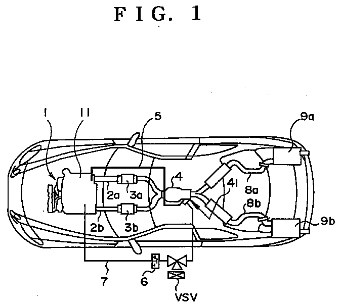
- Fig. 1 is a schematic view showing the automotive exhaust system to which the exhaust gas purifying apparatus for an internal combustion engine according to the present invention is applied.
- the exhaust system after two exhaust pipes 2a and 2b connected to an engine 1 are once emerged into a single pipe, the exhaust pipes are separated into two exhaust pipes 8a and 8b.
- Each of the exhaust pipes 8a and 8b is connected to a muffler 9a, 9b located in the rear side of the chassis.
- Catalysts 3a and 3b for purifying the exhaust gas are provided in the two exhaust gas pipes 2a and 2b.
- An adsorbent sleeve 4 is provided at a portion in which the exhaust pipes 2a and 2b are merged into one downstream of the catalysts 3a and 3b.
- the interior of the adsorbent sleeve 4 is divided into two flow paths A and B. These flow paths A and B correspond to the first gas exhaust flow path and the second exhaust gas flow path according to the present invention, respectively.
- a zeolite system adsorbent 42 is provided in the flow path A as the adsorbent of the present invention.
- the adsorbent 42 adsorbs the hydrocarbon (HC) contained in the exhaust gas.
- a recirculation pipe 5 is connected to the downstream side of the adsorbent 42 in the flow path A.
- the recirculation pipe 5 is connected to a serge tank 11 provided in an intake pipe of the engine and is used for the exhaust gas recirculation (EGR).
- a flow rate control valve (EGR valve) 10 is mounted in the midway of the recirculation pipe 5.
- the flow rate control valve 10 is provided with a stator 14 composed of a four-phase magnetically exciting coil 13, a magnetized cylindrical rotor 15 which rotates within the stator 14, and a stepper motor 17 having a rod 16 which threadedly engages with in the cylindrical rotor 15 and projects and retracts in accordance with the rotation of the cylindrical rotor 15.
- a movable plate 18 which is spring-biased in a direction in which the rod 16 is projected is mounted at the tip end of the rod 16 of the stepper motor 17. Furthermore, a valve 22 which is seated to the seat within the recirculation pipe 5 is provided at the tip end of a valve rod 19 which is in contact with or out of contact with the movable plate 18.
- the movable plate 18 and the rod 16 are normally biased in the advance direction and the valve 22 of the valve rod 19 is seated to the seat to interrupt the flow path within the recirculation pipe 5.
- the recirculation pipe 5 and the flow rate control valve 10 realize the recirculation means according to the present invention.
- a bypass valve 40 for selectively opening/closing the flow path A and the flow path B is mounted in the outlet portion C of the adsorbent sleeve 4.
- the bypass valve 40 is connected through a lever 43 and a diaphragm chamber 41 mounted outside the adsorbent sleeve 4.
- the lever 43 rotates about a furculum 44.
- the bypass valve 40 is lifted by the end portion of the lever 43 on the side of the bypass valve 40.
- the flow path B is opened and the flow path A is closed.
- a pipe 7 whose one end is connected to an intake pipe (not shown) of the engine is connected at the other end to the above-described diaphragm chamber 41 so that a negative pressure within the intake pipe may be introduced to the engine.
- a check valve 6 for allowing only the negative pressure to be applied from intake pipe side to the diaphragm chamber side, and a vacuum switching valve VSV for closing the pipe 7 when a current is supplied thereto and for closing the pipe 7 when a current is not supplied thereto.
- the vacuum switching valve VSV closes the pipe 7, so that the negative pressure to the diaphragm chamber 41 is interrupted and the diaphragm chamber 41 is released to the atmosphere.
- the end portion of the lever 43 on the side of the diaphragm chamber 41 is lowered by the spring force of the diaphragm per se.
- the end portion of the lever 43 on the bypass valve side lifts the bypass valve 40.
- the bypass valve 40 closes the flow path A and opens the flow path B.
- the vacuum switching valve VSV opens the pipe 7, so that the negative pressure is introduced to the diaphragm chamber 41.
- the diaphragm chamber 41 lifts the end portion of the lever 43 on the side of the diaphragm chamber 41.
- the lever 43 is rotated about the furculum 44, and the end portion of the lever 43 on the side of the bypass valve 40 lowers the bypass valve.
- the bypass valve 40 opens the flow path A and closes the flow path B.
- bypass valve 40 realizes the passage switching means according to the present invention.
- the controller system for controlling the above-described exhaust system will be described with reference to Fig. 4.
- the controller system includes a water temperature sensor 108, a throttle opening degree sensor 109, an air flow meter 110, and a crank position sensor 111 each of which is connected to an electronic control unit (ECU) 100.
- ECU electronice control unit
- the water temperature sensor 108 realizes the water temperature detecting means according to the present invention and detects a temperature of cooling water for the engine 1.
- the throttle opening degree sensor 109 outputs a voltage in proportion to the opening degree of the throttle valve provided in the intake pipe of the engine 1. The output signal is used for discriminating whether or not the engine 1 is in the idle condition.
- the air flow meter 110 realizes the operational condition detecting means together with the crank position sensor 111 to be described later and outputs a voltage in proportion to an air amount Ga sucked to the engine 1.
- the crank position sensor 111 outputs a pulse signal for every predetermined angular rotation of the crank shaft.
- the output signal is used for calculating the revolutions per minute NE of the engine 1.
- the output signal of the crank position sensor 111 is used for calculating the intake air amount GN per one turn of the engine 1 together with the output signal of the air flow meter 110.
- the calculated RPM NE and the intake air amount GN per one turn are used as data representative of the load condition of the engine 1.
- the above-described position sensor 111 and the air flow meter 110 are used to realize the operational condition detecting means according to the present invention.
- the ECU 100 controls the above-described exhaust system on the basis of the signals from the respective sensors.
- an ECU for a fuel injection control may be used or an ECU specialized for the exhaust gas purifying apparatus may be used.
- the ECU 100 is provided with CPU 101, ROM 102, RAM 103 and input/output (I/O) port 105. These are connected to bus 104. A drive circuit 107 and an A/D converter 106 are connected to the input port (I/O) 105.
- the above-described ROM 102 stores therein various control maps and application programs to be executed by the CPU 101.
- the control map of the ROM 102 represents the relationship between the load condition determined by the intake air amount GN per one revolution of the engine 1 and the engine RPM NE and the number of steps corresponding to an opening degree (recirculation amount) of the flow rate control valve 10.
- this map A in the case where the intake air amount GN per one revolution is kept constant, if the engine RPM NE is increased, the number of the steps is increased so that the recirculation amount is increased.
- the intake air amount GN per one revolution is kept constant
- the number of the steps is increased so that the recirculation amount is increased.
- "20" is selected as the target number of the steps for the flow rate control valve 10.
- the intake air amount GN and the engine RPM NE load region b in Fig.
- FIG. 6 represents a relationship between a temperature THW of the cooling water and an coefficient kptemp.
- the coefficient kptemp is a compensation coefficient multiplied to the target step number specified by the map A.
- the ROM 102 stores, as a control map, a map C (not shown) representative of a relationship between the cooling water temperature THW when the engine is started and a period of time (hereinafter referred to as a catalyst activation time) from a time of the engine start until the catalysts 3a and 3b are activated.
- This map C and the CPU 101 constitute the activation discriminating means according to the present invention. Namely, the operation time period from the start of the engine 1 reaches the catalyst activation time, it is judged that the catalysts 3a and 3b are activated, whereas the operation time period of the engine is shorter than the catalyst activation time, it is judged that the catalysts 3a and 3b are not activated.
- the CPU 101 operates in accordance with the application program of the ROM 102 and controls the flow rate control valve 10 and the vacuum switching valve VSV through the above-described drive circuit 107.
- the RAM 103 stores therein, the signals from the temperature sensor 108, the throttle opening degree sensor 109, the air flow meter 110 and the crank position sensor 111 and the calculation results of the CPU 101 (for example, the intake air amount GN per one revolution, the engine RPM NE and the like).
- the signals from the respective sensors are rewritten as newest signals for every constant time period (for example, at every output of the crank position sensor 111).
- EGR exhaust gas recirculation
- a threshold value for example, 80°C
- the execution conditions of the EGR for instance, there are exemplified conditions whether a predetermined period of time has lapsed from the engine start or not, whether the warming-up of the engine has been completed or not, whether the RPM of the engine 1 is equal to or less than the predetermined RPM or not, whether the engine is in the off-idle condition or not, or the like.
- the RAM 103 has a region for storing therein the target step number read out from the map A of the ROM 102, or the coefficient kptemp read out from the map B.
- the A/D converter 106 converts the output signals from the water temperature sensor 108, the throttle opening degree sensor 109, and the air flow meter 110 from the analog signals into the digital signals and inputs the converted signals into the I/O port 105.
- the drive circuit 107 is connected to the flow rate control valve 10 and the vacuum switching valve VSV. Then, when the drive circuit 107 receives from the CPU 101 an electric supply order comparison signal for driving the flow rate control valve 10 up to the target step number, the drive circuit 107 drives the flow rate control valve 10 in accordance with the signal. Also, when the drive circuit 107 receives from the CPU 101 a switching signal between an electric supply and non-electric supply of the vacuum switching valve, the drive circuit 107 drives the vacuum switching valve VSV in accordance with the signal.
- the CPU 101 supplies the vacuum switching valve VSV with an electric power from the drive circuit 107.
- the vacuum switching valve VSV which is in the electric supply condition receiving the electric power opens the flow path A within the adsorbent sleeve 4 and closes the flow path B.
- the flow rate control valve 10 of the recirculation pipe 5 is kept under the fully closed condition. At this time, all the exhaust gas discharged from the catalysts 3a and 3b is discharged to the exhaust pipes 8a and 8b through the flow path A.
- the hydrocarbon (HC) which has not been oxidized by the catalysts is adsorbed to the adsorbent 42 in the flow path A.
- the CPU 101 reads out the output signal (cooling water temperature) from the water temperature sensor 108. Then, the CPU 101 accesses the map C of the ROM 102, reads out the catalyst activation time corresponding to the cooling water temperature and compares the catalyst activation time with the operation time period from the engine start until the current point. When the operational time period of the engine 1 reaches the catalyst activation time, the CPU 101 interrupts the electric supply from the drive circuit 107 to the vacuum switching valve.
- the vacuum switch valve VSV to which the electric supply is interrupted and kept in the non-electric supply condition closes the flow path A and opens the flow path B within the adsorbent sleeve 4.
- the exhaust gas purified by the activated catalysts 3a and 3b is introduced into the exhaust pipes 8a and 8b through the flow path B within the adsorbent sleeve 4 and flows into the mufflers 9a and 9b.
- the CPU 101 discriminates whether or not the bypass valve 40 closes the flow path A and the opens the flow path B; namely whether or not the catalysts 3a and 3b are activated (step 701).
- the target opening degree (target step number) of the flow rate control valve 10 is set to "0" (step 708), and the closed condition of the flow rate control valve 10 is maintained (step 707). Namely, the recirculation is not performed.
- step 701 if the CPU 101 judges that the bypass valve 40 closes the flow path A and at the same time opens the flow path B; namely, that the catalysts 3a and 3b are activated, the process is advanced to step 702.
- step 702 the CPU 101 accesses the RAM 103 and reads out the intake air amount GN per one revolution of the engine 1 and the RPM NE. Then, the CPU 101 accesses the map A of the ROM 102, and reads out the target step number (opening degree of the flow rate control valve 10) corresponding to the intake air amount GN per one revolution and the RPM NE. Furthermore, the CPU 101 writes the read-out target step number as the target opening degree in the RAM 103.
- the CPU 101 inputs into the drive circuit 107 the supply order comparison signal corresponding to the target opening degree (target step number) written in the RAM 103 and drives the flow rate control valve 10 to the target step number (step 707). Namely, the recirculation pipe 5 is opened in correspondence with the number of the target step number.
- the process of the above-described steps 701, 702, 703 and 707 shows the regular exhaust gas recirculation (EGR) to be performed when the EGR execution conditions are met after the warming-up of the engine 1).
- EGR exhaust gas recirculation
- the CPU 101 jumps to the above-described step 707, inputs into the drive circuit 107 the supply order comparison signal corresponding to the target opening degree (target step number) written in the RAM 103 and drives the flow rate control valve 10 to the target step number. Namely, the recirculation pipe 5 is opened in correspondence with the number of the target step number.
- the CPU 101 reads out the cooling water temperature THW stored in the RAM 103, and thereafter accesses the map B of the ROM 102. Then, the CPU 101 reads out the coefficient kptemp corresponding to the cooling water temperature THW from the map B. Furthermore, the CPU 101 multiplies the target opening degree (target step number) of the RAM 103 by the coefficient kptemp to thereby calculate the new target opening degree (new target step number) (step 706).
- the CPU 101 inputs into the drive circuit 107 the supply order comparison signal corresponding to the newly calculated target opening degree (new target step number) in the same order as in the above-described step 707, and drives the flow rate control valve 10 up to the target step number.
- the ordinate axis represents the intake air amount GN per one revolution of the engine 1 and the abscissa axis represents the RPM NE of the engine 1.
- the region A in Fig. 8 shows a region where the normal exhaust gas recirculation (EGR) is to be performed, and the region B shows a region where the exhaust gas recirculation according to the present invention is to be performed.
- EGR normal exhaust gas recirculation
- the exhaust gas recirculation is not performed.
- the exhaust gas purifying apparatus for an internal combustion engine even if the conditions of the steps 704 and 705 are not met, it is possible to perform the exhaust gas recirculation to an extent corresponding to the engine condition at that time (load condition or the load condition and cooling water temperature THW).
- the exhaust gas purifying apparatus for an internal combustion engine according to the embodiment since the exhaust gas recirculation is performed even in the load region (region B in Fig. 8) where the exhaust gas recirculation (EGR) is not to be performed in the normal exhaust gas recirculation process, it is possible to perform the exhaust gas recirculation in the broad range. It is possible to early separate and recirculate the unburnt gas components of the adsorbent 42. Also, in the embodiment, in the region B in Fig. 8, since the exhaust gas recirculation is performed to the extent corresponding to the condition of the engine 1, it is possible to stabilize the engine 1.
- the temperature variation of the adsorbent 42 in the case where only the regular exhaust gas recirculation (EGR) process is only performed, and the temperature variation of the adsorbent 42 in the case where the exhaust gas recirculation process according to the embodiment is performed are shown in Fig. 9 in which the ordinate axis represents the temperature of the adsorbent 42 and the abscissa axis represent the time.
- EGR normal exhaust gas recirculation
- the temperature rise rate of the adsorbent 42 is high.
- the exhaust gas is not caused to flow through the adsorbent 42 from the time when the catalysts 3a and 3b are activated (ii in Fig. 9) until the time of completion of the warming-up (iii in Fig. 9)
- the adsorbent 42 is heated only the heat transfer from the exhaust gas that flows through the flow path B, so that it takes a long time until the temperature reaches the separation temperature of the hydrocarbon (HC).
- the part of the exhaust gas (the amount of the exhaust gas corresponding to the condition of the engine 1) is caused to flow through the adsorbent 42.
- the adsorbent 42 is directly heated by the part of the exhaust gas and the temperature reaches the separation temperature of the hydrocarbon (HC) for a short period of time.
- the exhaust gas purifying apparatus for an internal combustion engine it is possible to perform the exhaust gas recirculation from the early stage of the start of the engine 1 in view of the condition of the engine 1, and it is therefore possible to complete the regeneration process of the adsorbent in the earlier stage.
- a fear of the engine stall before the completion of the separation of the hydrocarbon (HC) is suppressed and it is thus possible to avoid the degradation of the performance of the adsorbent.
- the difference DTDCP shows a positive value if the current combustion condition is worse than the previous combustion condition.
- the value of the difference DTDCP shows a positive value depending upon the engine load change in some cases, in order to distinguish the case where the combustion condition is worse and the case where the engine load is changed, it is necessary to clarify the value that the difference DTDCP takes according to the change of the engine load.
- the ROM 102 of the ECU 10 stores therein a map D representative of a relationship between the intake air amount GN per one revolution specified by the intake air amount Ga of the engine 1 and the engine RPM NE and the judgment constant kdcp specifying the allowable range of the difference DTDCP.
- the CPU 101 accesses the map D, reads out the judgement constant kdcp corresponding to the intake air amount GN per one revolution of the engine 1 and compares the read-out judgement constant kdcp with the difference DTDCP.
- the CPU 101 judges that the value of the difference DTDCP is greater than the judgement constant kdcp, the CPU 101 judges that the combustion condition of the engine 1 becomes worse.
- the CPU 101 judges that the value of the difference DTDCP is smaller than the judgement constant kdcp, the CPU 101 judges that the combustion condition of the engine 1 becomes stable.
- crank position sensor 111 the CPU 101 and the map D constitute the combustion condition detecting means according to the present invention.
- the other structure thereof is the same as that of the foregoing embodiment, and hence the explanation therefor will be omitted.
- Fig. 11 shows the target opening degree compensation routine for the exhaust gas recirculation which is executed by the CPU 101 whenever the crank position sensor 111 issues an output (every time the crank shaft is rotated through 30°).
- the CPU 101 discriminates whether the catalysts 3a and 3b are activated (step 1101). In this case, if the catalysts 3a and 3b are not activated, the CPU 101 sets the target opening degree (target step number) of the flow rate control valve 10 to "0" (step 1102).
- the upper limit protective process is a process for preventing the target opening degree (target step number) from exceeding the allowable range due to the erroneous detection of each sensor.
- the CPU 101 discriminates whether or not the target opening degree (target step number) set in the above-described step 1102 is equal to or less than the upper limit. If the target opening degree (target step number) is equal to or less than the upper limit, the above-described target opening degree is written in the RAM 103 as the target opening degree for the exhaust gas recirculation. On the other hand, if the target opening degree (target step number) is greater than the upper limit, the CPU 101 writes the above-described target opening degree in the RAM 103 as the target opening degree for the exhaust gas recirculation (step 1104).
- the CPU 101 since the target step number "0" is set in the above-described step 1102, the CPU 101 writes the target step number "0" to the RAM 103 without any modification.
- the CPU 101 judges that the catalysts 3a and 3b are activated in the step 1101 and advances to the step 1105.
- the CPU 101 reads out the initial value of the target opening degree (target step number) stored in advance in the RAM 103.
- the initial value is a small value (for example, step number "1") at which the combustion condition of the engine 1 does not become worse.
- step 1107 if it is judged that the output of the crank position sensor 111 is the signal representative of 30°after the top dead center, the CPU 101 calculates the time period T30Dn which have been expended from the top dead center to 30° after the top dead center, at the same time accesses the RAM 103 to read out the time period T30Dn-1 needed for the previous rotation. Then, the CPU 101 subtracts the time period T30Dn-1 needed for the previous rotation from the time period T30Dn needed for the current rotation and calculates the difference DTDCP (step 1108).
- the CPU 101 accesses the RAM 103 and reads out the intake air amount GN per one revolution of the engine 1. Then, the CPU 101 accesses the map D of the ROM 102 and reads out the judgement constant kdcp corresponding to the intake air amount GN per one revolution (1109).
- the CPU 101 compares the difference DTDCP calculated in the above-described step 1108 with the judgement constant kdcp read out in the above-described step 1109 (step 1110).
- step 1110 if the difference DTDCP is greater than the judgement constant kdcp, the CPU 101 judges that the combustion condition of the engine 1 becomes worse due to the exhaust recirculation. Then, the CPU 101 reads out the target opening degree (target step number) for the exhaust gas recirculation stored in the RAM 103, and multiplies the target opening degree (target step number) by the compensation coefficient less than 1 (for example, 0.98), and calculates a new target opening degree (new target step number) (step 1111).
- the CPU 101 executes the upper limit protective process as in the step 1103 as to the new target opening degree (new target step number).
- the value obtained by the upper limit protective process is written in the RAM 103 as the target opening degree for the new exhaust recirculation.
- the CPU 101 compares the difference DTDCP with the value obtained by multiplying the judgement constant kdcp by the coefficient less than 1 (for example, 0.9) (step 1112).
- step 1112 if it is judged that the difference DTDCP is greater than the value obtained by multiplying the judgement constant kdcp by the coefficient less than 1, the CPU 101 judges that the combustion condition of the engine 1 is stable and the recirculation amount is suitable. The CPU does not execute the compensation of the target opening degree.
- step 1112 if it is judged that the difference DTDCP is equal to or smaller than the value obtained by multiplying the judgement constant kdcp by the coefficient less than 1, the CPU 101 judges that the combustion condition of the engine 1 is stable and the recirculation amount may be increased. In this case, the CPU 101 multiplies the target opening degree (target step number) stored in the RAM 103 by the coefficient not less than "1" (for example, 1.01) to thereby calculate the new target opening degree (new target step number) (step 1113).
- target step number stored in the RAM 103 by the coefficient not less than "1" (for example, 1.01)
- the CPU 101 executes the upper limit protective process for the target opening degree newly calculated (new target step number), and writes the value obtained through the upper limit protective process as the target opening degree for the new exhaust recirculation in the RAM 103.
- the CPU 101 executes the EGR control routine shown in Fig. 12 for every predetermined time period (for example, every 16 msec).
- the target step number target opening degree of the flow rate control valve 10
- the CPU 101 inputs into the drive circuit 107 the supply order comparison signal corresponding to the target step number read out in the above-described step 1202 and drives the flow rate control valve 10 up to the target step number (step 1203). Namely, the flow rate control valve 10 opens the recirculation pipe 5 to such an extent corresponding to the target step number.
- step 1204 if it is judged that the catalysts 3a and 3b are not activated, the CPU 101 set the target opening value (target step number) of the flow rate control valve 10 as "0" (step 1207), and maintains the closed condition of the flow rate control valve. Namely, the exhaust recirculation is not executed.
- step 1204 if it is judged that the catalysts 3a and 3b are activated, the CPU 101 refers to the exhaust recirculation completion flag XEGR of the RAM 103, and discriminates whether or not the exhaust recirculation has already been completed, i.e., whether or not the regeneration of the adsorbent 42 has been completed (step 1205).
- the CPU 101 executes the same process as in the above-described step 1203, inputs into the drive circuit 107 the supply order comparison signal corresponding to the target opening degree (target step number) for the exhaust recirculation read out from the RAM 103, and drives the flow rate control valve 10 up to the target step number. Namely, the flow rate control valve 10 opens the recirculation pipe 5 to such an extent corresponding to the target step number.
- the CPU 101 judges the completion of the exhaust recirculation in the above-described step 1205, and sets the target opening degree (target step number) to "0" in the same way as in the above-described step 1207. Then, the CPU 101, in the same way as in the process in the above-described step 1203, inputs into the drive circuit 107 the supply order comparison signal corresponding to the target opening degree "0" (target step number), and drives the flow rate control valve 10 up to the target step number "0". Namely, the flow rate control valve 10 closes the recirculation pipe 5 according to the target step number "0".
- the exhaust gas purifying apparatus for an internal combustion engine it is possible to determine the amount of the exhaust recirculation in accordance with the load condition of the engine and to compensate for the amount of the exhaust gas to be recirculated by feeding back the combustion condition of the engine 1. It is thus possible to suppress the misfire or the engine stall due to the exhaust gas recirculation.
- a method is adapted to monitor the time period needed for the crank shaft of the engine 1 to rotate through the constant angle
- the stepper motor type valve is exemplified as the flow rate control valve.
- the application is not limited thereto.
- an exhaust gas purifying apparatus includes a first exhaust flow path and a second exhaust flow path branched downstream of the catalyst; a n adsorbent disposed in the first exhaust flow path for adsorbing unburnt gas components contained in the exhaust gas; and a recirculating device for recirculating at least part of the exhaust gas discharged from the adsorbent to an intake side of the internal combustion engine.
- a operational condition of the internal combustion engine is detected.
- a recirculation amount of the exhaust gas is changed in accordance with the detected operational condition.
Landscapes
- Engineering & Computer Science (AREA)
- Chemical & Material Sciences (AREA)
- Combustion & Propulsion (AREA)
- Mechanical Engineering (AREA)
- General Engineering & Computer Science (AREA)
- Biomedical Technology (AREA)
- Health & Medical Sciences (AREA)
- Environmental & Geological Engineering (AREA)
- Analytical Chemistry (AREA)
- General Chemical & Material Sciences (AREA)
- Oil, Petroleum & Natural Gas (AREA)
- Chemical Kinetics & Catalysis (AREA)
- Exhaust Gas After Treatment (AREA)
- Exhaust-Gas Circulating Devices (AREA)
- Output Control And Ontrol Of Special Type Engine (AREA)
Abstract
Description
Claims (13)
- An exhaust gas purifying apparatus for an internal combustion engine, comprising:an exhaust pipe connected to the internal combustion engine;a catalyst mounted on said exhaust pipe;a first exhaust flow path and a second exhaust flow path branched downstream of said catalyst;a path switching means for introducing the exhaust gas into at least one of said first exhaust flow path and said second exhaust flow path;an adsorbing means disposed in said first exhaust flow path for adsorbing unburnt gas components contained in the exhaust gas;a recirculating means for recirculating at least part of the exhaust gas discharged from said adsorbing means to an intake side of the internal combustion engine;a operational condition detecting means for detecting a operational condition of the internal combustion engine; anda recirculation amount changing means for changing an amount of the exhaust gas to be recirculated by said recirculating means in accordance with the operational condition detected by said operational condition detecting means.
- The exhaust gas purifying apparatus according to claim 1, wherein said operational condition detecting means detects a load condition of the internal combustion engine, and said recirculation amount changing means changes the amount of the exhaust gas to be recirculated by said recirculating means in accordance with the load condition detected by said operational condition detecting means.
- The exhaust gas purifying apparatus according to claim 1, wherein said recirculating means recirculates, when the internal combustion engine is warming-up, at least part of the exhaust gas discharged from said adsorbing means to an intake side of the internal combustion engine.
- The exhaust gas purifying apparatus according to claim 1, further comprising an activation discriminating means for discriminating whether or not the catalyst is activated, wherein said recirculating means starts the recirculation of the exhaust gas under the condition that the activation discriminating means judges that the catalyst is activated.
- The exhaust gas purifying apparatus according to claim 4, wherein said activation discriminating means judges that the catalyst is activated when an operation time period from the start of the internal combustion engine is equal to or longer than a predetermined time period, and judges that the catalyst is not activated when the operation time period from the start of the internal combustion engine is shorter than the predetermined time period.
- The exhaust gas purifying apparatus according to claim 1, further comprising a water temperature detecting means for detecting a temperature of cooling water for an internal combustion engine, wherein said recirculating amount changing means compensates for the amount of the exhaust gas to be recirculated in accordance with the temperature of cooling water detected by said water temperature detecting means.
- The exhaust gas purifying apparatus according to claim 6, wherein said recirculating amount changing means compensates for the recirculating amount so that the amount of the exhaust gas to be recirculated is decreased in the case where the temperature of the cooling water is lower than a predetermined temperature.
- An exhaust gas purifying apparatus for an internal combustion engine, comprising:an exhaust pipe connected to the internal combustion engine;a catalyst mounted on said exhaust pipe;a first exhaust flow path and a second exhaust flow path branched downstream of said catalyst;a path switching means for introducing the exhaust gas into at least one of said first exhaust flow path and said second exhaust flow path;an adsorbing means disposed in said first exhaust flow path for adsorbing unburnt gas components contained in the exhaust gas;a recirculating means for recirculating at least part of the exhaust gas discharged from said adsorbing means to an intake side of the internal combustion engine;a combustion condition detecting means for detecting a combustion condition of the internal combustion engine; anda recirculation amount changing means for changing an amount of the exhaust gas to be recirculated by said recirculating means in accordance with the combustion condition detected by said combustion condition detecting means.
- The exhaust gas purifying apparatus according to claim 8, wherein said combustion condition detecting means detects, when the internal combustion engine is warming-up, the combustion condition of the internal combustion engine, and said recirculation amount changing means changes the amount of the exhaust gas to be recirculated by said recirculating means in accordance with the combustion condition detected by said combustion condition detecting means.
- An exhaust gas purifying method for an internal combustion engine, comprising the following steps of:introducing exhaust gas from the internal combustion engine into at least one of two exhaust flow paths branched downstream of a catalyst;adsorbing unburnt gas components contained in the exhaust gas by an absorbing means provided in said one of exhaust flow paths;recirculating at least part of the exhaust gas from said adsorbing means to an intake side of the internal combustion engine;detecting a operational condition of the internal combustion engine; andchanging an amount of the exhaust gas to be recirculated to the intake side of the internal combustion engine in accordance with the operational condition of the internal combustion engine.
- The exhaust gas purifying method according to claim 10, wherein the operational condition of the internal combustion engine is a load condition of the internal combustion engine which has been warming-up.
- An exhaust gas purifying method for an internal combustion engine, comprising the following steps of:introducing exhaust gas from the internal combustion engine into at least one of two exhaust flow paths branched downstream of a catalyst;adsorbing unburnt gas components contained in the exhaust gas by an absorbing means provided in said one of exhaust flow paths;recirculating at least part of the exhaust gas from said adsorbing means to an intake side of the internal combustion engine;detecting a combustion condition of the internal combustion engine; andchanging an amount of the exhaust gas to be recirculated to the intake side of the internal combustion engine in accordance with the combustion condition of the internal combustion engine.
- The exhaust gas purifying method according to claim 12, wherein the combustion condition is a combustion condition of the internal combustion engine which has been warming-up.
Applications Claiming Priority (3)
| Application Number | Priority Date | Filing Date | Title |
|---|---|---|---|
| JP14050296A JP3596169B2 (en) | 1996-06-03 | 1996-06-03 | Exhaust gas purification device for internal combustion engine |
| JP14050296 | 1996-06-03 | ||
| JP140502/96 | 1996-06-03 |
Publications (2)
| Publication Number | Publication Date |
|---|---|
| EP0816647A1 true EP0816647A1 (en) | 1998-01-07 |
| EP0816647B1 EP0816647B1 (en) | 2003-03-12 |
Family
ID=15270139
Family Applications (1)
| Application Number | Title | Priority Date | Filing Date |
|---|---|---|---|
| EP97108756A Expired - Lifetime EP0816647B1 (en) | 1996-06-03 | 1997-06-02 | Exhaust gas purifying apparatus and method for internal combustion engine |
Country Status (4)
| Country | Link |
|---|---|
| US (1) | US5911681A (en) |
| EP (1) | EP0816647B1 (en) |
| JP (1) | JP3596169B2 (en) |
| DE (1) | DE69719615T2 (en) |
Cited By (2)
| Publication number | Priority date | Publication date | Assignee | Title |
|---|---|---|---|---|
| EP1691047A1 (en) * | 2005-02-15 | 2006-08-16 | Behr GmbH & Co. KG | Exhaust gas cleaning device for a combustion engine and method of treating exhaust gas |
| DE10158796B4 (en) * | 2000-12-01 | 2007-06-06 | Honda Giken Kogyo K.K. | Control system for an internal combustion engine |
Families Citing this family (8)
| Publication number | Priority date | Publication date | Assignee | Title |
|---|---|---|---|---|
| JP3564966B2 (en) | 1997-09-19 | 2004-09-15 | トヨタ自動車株式会社 | Failure diagnosis device for exhaust gas purification device |
| US6006732A (en) * | 1998-09-03 | 1999-12-28 | Navistar International Transportation Corp | Balanced flow EGR control apparatus |
| US6006733A (en) * | 1998-10-08 | 1999-12-28 | Navistar International Transportation | Exhaust gas recirculation apparatus |
| US6286306B1 (en) * | 1999-02-08 | 2001-09-11 | Honda Giken Kogyo Kabushiki Kaisha | Exhaust gas purification system of internal combustion engine |
| DE20102815U1 (en) | 2001-02-17 | 2001-05-17 | Dr.Ing.H.C. F. Porsche Ag, 70435 Stuttgart | Internal combustion engine with exhaust gas recirculation |
| DE10309468A1 (en) * | 2003-03-03 | 2004-09-23 | Dr.Ing.H.C. F. Porsche Ag | Exhaust pipe of an internal combustion engine with controllable exhaust flaps |
| US9205376B2 (en) | 2011-12-22 | 2015-12-08 | Continental Automotive Systems, Inc. | Automotive anti-contamination system |
| JP7391484B2 (en) * | 2021-08-31 | 2023-12-05 | ダイハツ工業株式会社 | Internal combustion engine control system |
Citations (7)
| Publication number | Priority date | Publication date | Assignee | Title |
|---|---|---|---|---|
| US3645098A (en) * | 1970-09-28 | 1972-02-29 | Gen Motors Corp | Exhaust emission control |
| DE4025565A1 (en) * | 1990-08-11 | 1992-02-13 | Audi Ag | Controlled IC exhaust gas buffer and recycle system - improving cold start=up efficiency of catalytic converters using an engine management device |
| EP0588315A1 (en) * | 1992-09-16 | 1994-03-23 | Nippondenso Co., Ltd. | Exhaust gas purification apparatus for internal combustion engine |
| US5307627A (en) * | 1993-01-07 | 1994-05-03 | Ford Motor Company | Method and apparatus for oxidizing hydrocarbons from exhaust gases |
| US5388405A (en) * | 1991-09-30 | 1995-02-14 | Hitachi, Ltd. | System for purifying exhaust gas for use in an automobile |
| EP0640381A1 (en) * | 1993-08-16 | 1995-03-01 | Corning Incorporated | Modified zeolite for trapping hydrocarbons |
| JPH0771237A (en) * | 1993-08-31 | 1995-03-14 | Toyota Motor Corp | Exhaust emission control device for internal combustion engine |
Family Cites Families (11)
| Publication number | Priority date | Publication date | Assignee | Title |
|---|---|---|---|---|
| DE588315C (en) * | 1932-03-01 | 1933-11-17 | Milo William Krejci | Incapacitation proceedings |
| US4497335A (en) * | 1979-12-21 | 1985-02-05 | Toyota Jidosha Kogyo Kabushiki Kaisha | Control valve of exhaust gas recirculation apparatus |
| US4625697A (en) * | 1983-11-04 | 1986-12-02 | Nissan Motor Company, Limited | Automotive engine control system capable of detecting specific engine operating conditions and projecting subsequent engine operating patterns |
| JPH0660570B2 (en) * | 1986-01-07 | 1994-08-10 | トヨタ自動車株式会社 | Exhaust gas purification device |
| JPH0623531B2 (en) * | 1986-01-09 | 1994-03-30 | トヨタ自動車株式会社 | Exhaust gas purification device for diesel engine |
| US5125231A (en) * | 1990-06-08 | 1992-06-30 | Corning Incorporated | Dual converter engine exhaust system for reducing hydrocarbon emissions |
| JPH05171929A (en) * | 1991-12-25 | 1993-07-09 | Nissan Motor Co Ltd | Exhaust emission control device for internal combustion engine |
| JP2694740B2 (en) * | 1992-07-17 | 1997-12-24 | 本田技研工業株式会社 | Engine exhaust purification device |
| JPH06173653A (en) * | 1992-12-07 | 1994-06-21 | Nissan Motor Co Ltd | Exhaust emission control device for internal combustion engine |
| JP3387983B2 (en) * | 1993-09-29 | 2003-03-17 | 本田技研工業株式会社 | Engine exhaust gas purification equipment |
| JP3460338B2 (en) * | 1994-10-31 | 2003-10-27 | 株式会社デンソー | Exhaust gas recirculation control device for internal combustion engine |
-
1996
- 1996-06-03 JP JP14050296A patent/JP3596169B2/en not_active Expired - Lifetime
-
1997
- 1997-06-02 DE DE69719615T patent/DE69719615T2/en not_active Expired - Fee Related
- 1997-06-02 EP EP97108756A patent/EP0816647B1/en not_active Expired - Lifetime
- 1997-06-03 US US08/867,725 patent/US5911681A/en not_active Expired - Lifetime
Patent Citations (7)
| Publication number | Priority date | Publication date | Assignee | Title |
|---|---|---|---|---|
| US3645098A (en) * | 1970-09-28 | 1972-02-29 | Gen Motors Corp | Exhaust emission control |
| DE4025565A1 (en) * | 1990-08-11 | 1992-02-13 | Audi Ag | Controlled IC exhaust gas buffer and recycle system - improving cold start=up efficiency of catalytic converters using an engine management device |
| US5388405A (en) * | 1991-09-30 | 1995-02-14 | Hitachi, Ltd. | System for purifying exhaust gas for use in an automobile |
| EP0588315A1 (en) * | 1992-09-16 | 1994-03-23 | Nippondenso Co., Ltd. | Exhaust gas purification apparatus for internal combustion engine |
| US5307627A (en) * | 1993-01-07 | 1994-05-03 | Ford Motor Company | Method and apparatus for oxidizing hydrocarbons from exhaust gases |
| EP0640381A1 (en) * | 1993-08-16 | 1995-03-01 | Corning Incorporated | Modified zeolite for trapping hydrocarbons |
| JPH0771237A (en) * | 1993-08-31 | 1995-03-14 | Toyota Motor Corp | Exhaust emission control device for internal combustion engine |
Non-Patent Citations (1)
| Title |
|---|
| PATENT ABSTRACTS OF JAPAN vol. 095, no. 006 31 July 1995 (1995-07-31) * |
Cited By (2)
| Publication number | Priority date | Publication date | Assignee | Title |
|---|---|---|---|---|
| DE10158796B4 (en) * | 2000-12-01 | 2007-06-06 | Honda Giken Kogyo K.K. | Control system for an internal combustion engine |
| EP1691047A1 (en) * | 2005-02-15 | 2006-08-16 | Behr GmbH & Co. KG | Exhaust gas cleaning device for a combustion engine and method of treating exhaust gas |
Also Published As
| Publication number | Publication date |
|---|---|
| DE69719615T2 (en) | 2004-01-15 |
| JPH09324622A (en) | 1997-12-16 |
| JP3596169B2 (en) | 2004-12-02 |
| EP0816647B1 (en) | 2003-03-12 |
| US5911681A (en) | 1999-06-15 |
| DE69719615D1 (en) | 2003-04-17 |
Similar Documents
| Publication | Publication Date | Title |
|---|---|---|
| US5544482A (en) | Exhaust gas-purifying system for internal combustion engines | |
| EP0811755B1 (en) | Exhaust gas purifying method and apparatus for internal combustion engine | |
| KR100555113B1 (en) | Exhaust gas purifier for internal combustion engines | |
| US5881552A (en) | Control system for internal combustion engines and control system for vehicles | |
| JPH0726599B2 (en) | Evaporative fuel control device for internal combustion engine | |
| US5542400A (en) | Apparatus and method for determining a failure of an EGR apparatus | |
| JPH1193645A (en) | Failure diagnosing device for exhaust emission control device | |
| JPH0932658A (en) | Function diagnostic device in evaporation purge device of internal combustion engine | |
| US5911681A (en) | Exhaust gas purifying apparatus and method for internal combustion engine | |
| US6978600B2 (en) | Secondary air supply system and secondary air supply method | |
| US6401451B1 (en) | Degradation discrimination system of internal combustion engine exhaust gas purification system | |
| US6877366B2 (en) | Test method for an exhaust gas catalytic converter and a corresponding testing device | |
| US6389804B1 (en) | Degradation discrimination system of internal combustion engine exhaust gas purification system | |
| EP1471219A1 (en) | Exhaust gas cleaning system and SOx poisoning recovery method for internal combustion engine | |
| JP3783430B2 (en) | Failure diagnosis device for hybrid vehicles | |
| JP4102302B2 (en) | Degradation state evaluation equipment for exhaust gas purification equipment | |
| JPH0777093A (en) | Method and device for diagnosing idle speed control system | |
| EP1517030B1 (en) | Method and apparatus for detecting deterioration in fuel injection amount of internal combustion engine | |
| JP3413997B2 (en) | Degradation diagnosis device for HC adsorbent in internal combustion engine | |
| JPH09125938A (en) | Engine control device | |
| JPH11247684A (en) | Fuel injection control device of internal combustion engine | |
| JPH11107810A (en) | Controller device for nox catalyzer | |
| JPH033936A (en) | Fuel injection quantity control system for internal combustion engine | |
| JPH08151964A (en) | Failure diagnostic device for fuel evaporative emission control system | |
| JPH08277753A (en) | Fault diagnostic device for fuel evaporation gas discharge suppressor |
Legal Events
| Date | Code | Title | Description |
|---|---|---|---|
| PUAI | Public reference made under article 153(3) epc to a published international application that has entered the european phase |
Free format text: ORIGINAL CODE: 0009012 |
|
| 17P | Request for examination filed |
Effective date: 19970701 |
|
| AK | Designated contracting states |
Kind code of ref document: A1 Designated state(s): DE FR GB |
|
| AKX | Designation fees paid |
Free format text: DE FR GB |
|
| RBV | Designated contracting states (corrected) |
Designated state(s): DE FR GB |
|
| 17Q | First examination report despatched |
Effective date: 19991220 |
|
| GRAG | Despatch of communication of intention to grant |
Free format text: ORIGINAL CODE: EPIDOS AGRA |
|
| GRAG | Despatch of communication of intention to grant |
Free format text: ORIGINAL CODE: EPIDOS AGRA |
|
| GRAH | Despatch of communication of intention to grant a patent |
Free format text: ORIGINAL CODE: EPIDOS IGRA |
|
| GRAH | Despatch of communication of intention to grant a patent |
Free format text: ORIGINAL CODE: EPIDOS IGRA |
|
| GRAA | (expected) grant |
Free format text: ORIGINAL CODE: 0009210 |
|
| AK | Designated contracting states |
Designated state(s): DE FR GB |
|
| REG | Reference to a national code |
Ref country code: GB Ref legal event code: FG4D |
|
| REF | Corresponds to: |
Ref document number: 69719615 Country of ref document: DE Date of ref document: 20030417 Kind code of ref document: P |
|
| ET | Fr: translation filed | ||
| PLBE | No opposition filed within time limit |
Free format text: ORIGINAL CODE: 0009261 |
|
| STAA | Information on the status of an ep patent application or granted ep patent |
Free format text: STATUS: NO OPPOSITION FILED WITHIN TIME LIMIT |
|
| 26N | No opposition filed |
Effective date: 20031215 |
|
| REG | Reference to a national code |
Ref country code: GB Ref legal event code: 746 Effective date: 20050707 |
|
| REG | Reference to a national code |
Ref country code: FR Ref legal event code: D6 |
|
| PGFP | Annual fee paid to national office [announced via postgrant information from national office to epo] |
Ref country code: DE Payment date: 20060525 Year of fee payment: 10 |
|
| PGFP | Annual fee paid to national office [announced via postgrant information from national office to epo] |
Ref country code: GB Payment date: 20060531 Year of fee payment: 10 |
|
| PGFP | Annual fee paid to national office [announced via postgrant information from national office to epo] |
Ref country code: FR Payment date: 20060608 Year of fee payment: 10 |
|
| GBPC | Gb: european patent ceased through non-payment of renewal fee |
Effective date: 20070602 |
|
| REG | Reference to a national code |
Ref country code: FR Ref legal event code: ST Effective date: 20080229 |
|
| PG25 | Lapsed in a contracting state [announced via postgrant information from national office to epo] |
Ref country code: DE Free format text: LAPSE BECAUSE OF NON-PAYMENT OF DUE FEES Effective date: 20080101 |
|
| PG25 | Lapsed in a contracting state [announced via postgrant information from national office to epo] |
Ref country code: GB Free format text: LAPSE BECAUSE OF NON-PAYMENT OF DUE FEES Effective date: 20070602 |
|
| PG25 | Lapsed in a contracting state [announced via postgrant information from national office to epo] |
Ref country code: FR Free format text: LAPSE BECAUSE OF NON-PAYMENT OF DUE FEES Effective date: 20070702 |