EP0815554B1 - Analysis-by-synthesis linear predictive speech coder - Google Patents
Analysis-by-synthesis linear predictive speech coder Download PDFInfo
- Publication number
- EP0815554B1 EP0815554B1 EP96908412A EP96908412A EP0815554B1 EP 0815554 B1 EP0815554 B1 EP 0815554B1 EP 96908412 A EP96908412 A EP 96908412A EP 96908412 A EP96908412 A EP 96908412A EP 0815554 B1 EP0815554 B1 EP 0815554B1
- Authority
- EP
- European Patent Office
- Prior art keywords
- excitation
- pulse
- bits
- code book
- speech
- Prior art date
- Legal status (The legal status is an assumption and is not a legal conclusion. Google has not performed a legal analysis and makes no representation as to the accuracy of the status listed.)
- Expired - Lifetime
Links
- 238000003786 synthesis reaction Methods 0.000 title claims description 23
- 230000005284 excitation Effects 0.000 claims description 119
- 230000003044 adaptive effect Effects 0.000 claims description 19
- 230000015572 biosynthetic process Effects 0.000 claims description 13
- 239000013598 vector Substances 0.000 description 54
- 230000035945 sensitivity Effects 0.000 description 37
- 238000004458 analytical method Methods 0.000 description 17
- 239000011159 matrix material Substances 0.000 description 15
- 238000000034 method Methods 0.000 description 15
- 230000009466 transformation Effects 0.000 description 7
- 238000010586 diagram Methods 0.000 description 6
- 230000004044 response Effects 0.000 description 6
- 238000005314 correlation function Methods 0.000 description 4
- 230000001413 cellular effect Effects 0.000 description 3
- 238000004891 communication Methods 0.000 description 2
- 238000001914 filtration Methods 0.000 description 2
- 230000007774 longterm Effects 0.000 description 2
- 238000007781 pre-processing Methods 0.000 description 2
- 101710170231 Antimicrobial peptide 2 Proteins 0.000 description 1
- 101000822695 Clostridium perfringens (strain 13 / Type A) Small, acid-soluble spore protein C1 Proteins 0.000 description 1
- 101000655262 Clostridium perfringens (strain 13 / Type A) Small, acid-soluble spore protein C2 Proteins 0.000 description 1
- 101000655256 Paraclostridium bifermentans Small, acid-soluble spore protein alpha Proteins 0.000 description 1
- 101000655264 Paraclostridium bifermentans Small, acid-soluble spore protein beta Proteins 0.000 description 1
- 230000003321 amplification Effects 0.000 description 1
- 238000013528 artificial neural network Methods 0.000 description 1
- 238000005311 autocorrelation function Methods 0.000 description 1
- 230000008859 change Effects 0.000 description 1
- 238000000605 extraction Methods 0.000 description 1
- 238000003199 nucleic acid amplification method Methods 0.000 description 1
- 238000005457 optimization Methods 0.000 description 1
- 230000000737 periodic effect Effects 0.000 description 1
- 238000013139 quantization Methods 0.000 description 1
- 238000007493 shaping process Methods 0.000 description 1
Images


Classifications
-
- G—PHYSICS
- G10—MUSICAL INSTRUMENTS; ACOUSTICS
- G10L—SPEECH ANALYSIS TECHNIQUES OR SPEECH SYNTHESIS; SPEECH RECOGNITION; SPEECH OR VOICE PROCESSING TECHNIQUES; SPEECH OR AUDIO CODING OR DECODING
- G10L13/00—Speech synthesis; Text to speech systems
-
- G—PHYSICS
- G10—MUSICAL INSTRUMENTS; ACOUSTICS
- G10L—SPEECH ANALYSIS TECHNIQUES OR SPEECH SYNTHESIS; SPEECH RECOGNITION; SPEECH OR VOICE PROCESSING TECHNIQUES; SPEECH OR AUDIO CODING OR DECODING
- G10L19/00—Speech or audio signals analysis-synthesis techniques for redundancy reduction, e.g. in vocoders; Coding or decoding of speech or audio signals, using source filter models or psychoacoustic analysis
- G10L19/04—Speech or audio signals analysis-synthesis techniques for redundancy reduction, e.g. in vocoders; Coding or decoding of speech or audio signals, using source filter models or psychoacoustic analysis using predictive techniques
- G10L19/08—Determination or coding of the excitation function; Determination or coding of the long-term prediction parameters
- G10L19/10—Determination or coding of the excitation function; Determination or coding of the long-term prediction parameters the excitation function being a multipulse excitation
-
- G—PHYSICS
- G10—MUSICAL INSTRUMENTS; ACOUSTICS
- G10L—SPEECH ANALYSIS TECHNIQUES OR SPEECH SYNTHESIS; SPEECH RECOGNITION; SPEECH OR VOICE PROCESSING TECHNIQUES; SPEECH OR AUDIO CODING OR DECODING
- G10L19/00—Speech or audio signals analysis-synthesis techniques for redundancy reduction, e.g. in vocoders; Coding or decoding of speech or audio signals, using source filter models or psychoacoustic analysis
- G10L19/04—Speech or audio signals analysis-synthesis techniques for redundancy reduction, e.g. in vocoders; Coding or decoding of speech or audio signals, using source filter models or psychoacoustic analysis using predictive techniques
- G10L19/06—Determination or coding of the spectral characteristics, e.g. of the short-term prediction coefficients
Definitions
- the present invention relates to an analysis-by-synthesis linear predictive speech coder.
- Such speech coders are used in e.g. cellular radio communication systems.
- An analysis-by-synthesis speech coder [1] consists of three main components in the synthesis part, namely a linear predictive coding (LPC) synthesis filter, an adaptive code book and some type of fixed excitation.
- LPC linear predictive coding
- the synthesis of the speech is done by filtering an excitation vector through the LPC synthesis filter to produce the synthetic speech signal.
- the excitation vector is formed by adding together scaled versions of vectors coming from the adaptive code book and the fixed excitation.
- the analysis part of an analysis-by-synthesis coder consists mainly of the LPC analysis and the excitation analysis.
- the excitation analysis is a search for the indices or other parameters for the excitation, e.g. indices for the code book, gain parameters for the excitation or the amplitudes and positions for excitation pulses.
- the used excitation structure in an analysis-by-synthesis speech coder is essential for the quality of the reconstructed speech, the complexity of the search and the robustness to bit errors.
- the excitation needs to be rich, i.e. contain both pulse-like and noise-like components.
- the excitation needs to be somewhat structured, due to the fact that the search for the excitation code tends to be of low complexity in a structured code book.
- the bit error sensitivity for the unprotected bits of the excitation code must be low.
- the mix usually consists of pulse and noise sequences. Pulse-like excitations are needed in onsets, plosive and voiced sections of the speech. Noise-like sequences are needed for unvoiced sounds.
- Multi-pulse excitation has been described in [9] and consists of pulses described by a position and an amplitude.
- Regular pulse excitation RPE
- RPE Regular pulse excitation
- TBPE Transformed binary pulse excitation
- VSE Vector sum excitation
- VSE Vector sum excitation
- index assignment [15] and phase position coding [16] have been proposed.
- TRPE-HLTP transformed binary regular pulse excitation-high resolution long-term prediction
- An object of the present invention is an analysis-by-synthesis linear predictive speech coder that provides both high quality (excitation richness), low search complexity and high robustness in a mobile radio environment.
- Fig. 1 shows a block diagram of a typical analysis-by-synthesis linear predictive speech coder.
- the coder comprises a synthesis part to the left of the vertical dashed center line and an analysis part to the right of said line.
- the synthesis part essentially includes two sections, namely an excitation code generating section 10 and an LPC synthesis filter 12.
- the excitation code generating section 10 comprises an adaptive code book 14, a fixed code book 16 and an adder 18.
- a chosen vector a I (n) from the adaptive code book 14 is multiplied by a gain factor g I for forming a signal p(n).
- an excitation vector from the fixed code book 16 is multiplied by a gain factor g J for forming a signal f(n).
- the signals p(n) and f(n) are added in adder 18 for forming an excitation vector ex(n), which excites the LPC synthesis filter 12 for forming an estimated speech signal vector s and(n).
- the estimated vector s and(n) is subtracted from the actual speech signal vector s(n) in an adder 20 for forming an error signal e(n).
- This error signal is forwarded to a weighting filter 22 for forming a weighted error vector e w (n).
- the components of this weighted error vector are squared and summed in a unit 24 for forming a measure of the energy of the weighted error vector.
- the filter parameters of filter 12 are updated for each speech signal frame (160 samples) by analyzing the speech signal frame in a LPC analyzer 28. This updating has been marked by the dashed connection between analyzer 28 and filter 12. Furthermore, there is a delay element 30 between the output of adder 18 and the adaptive code book 14. In this way the adaptive code book 14 is updated by the finally chosen excitation vector ex(n). This is done on a subframe basis, where each frame is divided into four subframes (40 samples).
- the used excitation structure of the fixed code book is essential for the quality of the reconstructed speech, the complexity of the search and the robustness to bit errors.
- the excitation needs to be rich, i.e. contain both pulse-like and noise-like components.
- the excitation needs to be somewhat structured.
- the search for the excitation code tends to be of relatively low complexity in a structured code book.
- the bit error sensitivity for the unprotected bits of the excitation code must be low. This is not as important for the protected (channel coded) bits of the excitation code.
- the bit error sensitivity in the excitation code should differ between protected and unprotected bits. Usually the unprotected class of bits will limit the performance in high BER channels.
- Multi-pulse excitation which is illustrated in Fig. 2, is known to provide high quality at higher bit rates. For example 6-8 pulses per 40 samples (or 5 milliseconds) is known to give good quality.
- Fig. 2 illustrates 6 pulses distributed over a subframe.
- the excitation vector may be described by the positions of these pulses (positions 7, 9, 14, 25, 29, 37 in the example) and the amplitudes of the pulses (AMP1-AMP6 in the example). Methods for finding these parameters are described in [9].
- AMP1-AMP6 amplitudes of the pulses
- Methods for finding these parameters are described in [9].
- the amplitudes only represent the shape of the excitation vector. Therefore a block gain is used to represent the amplification of this basic vector shape.
- FIG. 3 shows an example of the format of the bit distribution of a typical multi-pulse excitation consisting of six pulses.
- the bit error sensitivity of the multi-pulse excitation is known to be relatively high for some of the bits.
- Fig. 4 The figure illustrates the signal-to-noise ratio of reconstructed speech for 100% BER in each bit position of the excitation.
- each bit position in the format of Fig. 3 is individually set to the wrong value, while all other bit positions are correct.
- the reconstructed signal is compared to the original signal and the signal-to-noise ratio is computed.
- the length of each line in Fig. 4 represents the sensitivity of the reconstructed speech to an error in that bit position.
- high SNR indicates low bit error sensitivity.
- phase position coding [16]. This pulse position coding scheme has higher coding efficiency than a combinatorial scheme, but the trade off is somewhat lower speech quality.
- the principles of phase position coding are illustrated in Figs. 5a-e. In phase position coding the total number of positions are divided into a number of sub-blocks, 4 sub-blocks in the figure. Each sub-block contains a number of phases, ten phases in the figure. A restriction is imposed on the allowable pulse position. There is only one pulse allowed in each phase. This means that the positions can be coded by describing the phase positions and sub-block positions of the pulses. The phase positions are coded using a combinatorial scheme. The most significant bits of the sub-block positions will have high bit error sensitivity. On the other hand, the least significant bits of the phase position code words will have lower bit error sensitivity.
- Fig. 5a-e it is assumed that the pulses are generated by the same signal as the pulses in Fig. 2.
- the position of the strongest pulse is determined. This corresponds to the pulse in position 7 of fig. 2. This pulse has been indicated in Fig. 5a. Since pulse position 7 corresponds to phase 7, phase 7 of all the other sub-blocks has been crossed out as a forbidden pulse position for the remaining pulses.
- the second strongest pulse is determined in position 14, which corresponds to sub-block 2 and phase 4, which means that phase 4 is forbidden for the remaining pulses.
- Fig. 5c and 5d the pulses in positions 25 and 29 are determined in a similar way. The next pulse to be determined is the pulse corresponding to the pulse in position 9 of fig. 2.
- phase 9 is now forbidden. Therefore the pulse has to be positioned in one of the phase positions that are still allowed. The position chosen is that which gives the best approximation of the target excitation.
- the pulse is positioned in phase 8 of sub-block 1. Note that since the pulse has been shifted relative to the corresponding pulse (AMP2) in fig. 2, the amplitude may also have changed. Finally, the remaining pulse corresponding to the pulse in position 37 in fig. 2 is determined. This phase (7) is also forbidden. Instead a pulse is generated in phase position 6 of sub-block 4. This pulse has been indicated by a dashed line in fig. 5e.
- the decoder at the receiving end does not know which of the pulses that are most important.
- the most important pulses are also the pulses that are most sensitive to bit errors.
- the most important pulses are usually found first in the sequential search in the coder and usually have the largest amplitudes.
- due to the position coding the most sensitive information is spread out over the bits. This increases the level of sensitivity for all bits instead of giving an unequal bit error sensitivity, as would be desirable.
- One solution to this would be to split the pulses into two groups. The first group would consist of the first found pulses. This would make the first group more sensitive to bit errors.
- a drawback of the splitting method is that the coding efficiency of the second group is lower. Thus, a more efficient coding of the second group of the excitation is needed. Low error sensitivity is also needed, since these bits are candidates for being sent unprotected.
- a stochastic code book excitation is known to provide high quality at lower bit rates than a multi-pulse excitation.
- the complexity to search a stochastic code book is high, making implementation difficult, if not impossible.
- Techniques to lower the complexity exist, e.g. shifted sparse code books.
- the complexity is still too high for higher bit rates.
- Another drawback is the bit error sensitivity. A single bit error will make the decoder use a totally different stochastic sequence from the code book.
- the transformed binary pulse excitation (TBPE) is known to provide close to stochastic excitation efficiency at equivalent bit rates.
- the structure of such a code book makes the search highly efficient.
- the storage requirement in ROM is also low.
- the transformation matrices are used to make the excitation more gaussian-like.
- the inherent structure with regular spacing of the pulses make the excitation sparse.
- the main drawback of this method is that the quality drops when the low complexity search methods are kept while the code book size is increased.
- the regular spacing limits the increase in performance when the bit rate is increased.
- TBPE is described in detail in [11-12] and is further described below with reference to Figs. 6a-b.
- Fig. 6a illustrates the principles behind transformed binary pulse excitation.
- the binary pulse code book may comprise of vectors containing for example 10 components. Each vector component points either up (+1) or down (-1) as illustrated in Fig. 6a.
- the binary pulse code book contains all possible combinations of such vectors.
- the vectors of this code book may be considered as the set of all vectors that point to the "corners" of a 10-dimensional "cube". Thus, the vector tips are uniformly distributed over the surface of a 10-dimensional sphere.
- TBPE contains one or several transformation matrices (MATRIX 1 and MATRIX 2 in Fig. 6a). These are precalculated matrices stored in ROM. These matrices operate on the vectors stored in the binary pulse code book to produce a set of transformed vectors. Finally, the transformed vectors are distributed on a set of excitation pulse grids. The result is four different versions of regularly spaced "stochastic" code books for each matrix. A vector from one of these code books (based on grid 2) is shown as a final result in Fig. 6a.
- the object of the search procedure is to find the binary pulse code book index of the binary code book, the transformation matrix and the excitation pulse grid that together give the smallest weighted error.
- the matrix transformation step is further illustrated in Fig. 6b.
- the binary pulse code book is assumed to consist of only two positions (this is an unrealistic assumption, but it helps to illustrate the principles behind the transformation step).
- All the possible binary vectors of the binary pulse code book are illustrated in the left part of Fig. 6b. These vectors may be considered as being equivalent to vectors pointing to the corners of a 2-dimensional "cube", which is a square, that has been indicated by dotted lines in the left part of Fig. 6b.
- These vectors are now transformed by a matrix.
- This matrix may for example be an orthogonal matrix, which rotates the entire "cube".
- the transformed binary vectors comprise the projections of the individual transformed vectors on the X- and Y-axes, respectively.
- the resulting transformed binary code is illustrated in the right part of Fig. 6b. After transformation the transformed vectors are distributed on a set of grids, as explained with reference to Fig. 6a.
- Fig. 7 shows the bit allocation format of a typical TBPE excitation.
- TBPE code book 1 is a 40 sample code book and the second stage is divided into two 20 sample TBPE code books 2A, 2B.
- Code book 1 uses ten bits for the binary pulse code book index, two bits for the grids of code book 1, one bit for the matrices of code book 1 and four bits for the gain of code book 1.
- bit error sensitivity for the transformed binary pulse excitation defined in Fig. 7 is shown in Fig. 8.
- the inherent structure of TBPE gives a gray-coded index in the binary pulse code books. This means that code words close in hamming distance are also close in excitation vector distance. A single bit error will only change the sign of one of the regular pulses. Therefore the bit positions in the index have roughly equal sensitivity in Fig. 8 (bits 1-10 for binary pulse code book 1, bits 18-23 for binary pulse code book 2A and bits 32-37 for binary pulse code book 2B).
- the first code book including index, grid and matrix has higher sensitivity.
- the matrix bit (bit 13) shows a very high sensitivity in this example.
- the code book gain of the first code book shows higher sensitivity than the second code book gains (bits 28-31, 42-45).
- One problem is that the sensitivity is spread out over the bits. The sensitivity is generally lower than for multi-pulse excitation bits, but there is only a weakly unequal error sensitivity.
- the structure combines inherent index assignment and low complexity. This makes TBPE a strong candidate for replacing the second part of the multi-pulse excitation discussed above.
- the structure proposed in the present invention is a mixed excitation using a few multi-pulses and a TBPE code book.
- the positions of the pulses are preferably coded with a restricted position coding scheme, such as phase position coding described above.
- the mixed excitation using pulses and transformed binary pulse (noise) sequences improve quality.
- the MPE and TBPE searches are low complexity schemes.
- the mix of multi-pulse bits and TBPE shows strongly unequal error sensitivity, which fits into an unequal error protection scheme with some bits unprotected.
- Fig. 9 illustrates an example of the format of the bit allocation in a preferred embodiment of the present invention.
- this example there are three multi-pulses and one 13 bit index (13 binary pulses) TBPE code book with four grids and two matrices.
- Fig. 10 illustrates the bit sensitivity of the mixed excitation in accordance with the preferred embodiment of the invention. From Fig. 10 it is apparent that the few multi-pulses (bits 1-21) are more sensitive to bit errors than the TBPE code book index (bits 26-41).
- the phase position coding makes some of the bits for the pulse positioning less sensitive to bit errors (bits 1-3 of the sub-block positions and bits 11-12 of the phase code words).
- the amplitudes of the pulses (bits 14-15, 17-18, 20-21) are less sensitive than the signs (bits 13, 16, 19).
- the bits in the TBPE index bits 26-38) are equal in sensitivity and the sensitivity is very low compared to the pulse signs and positions.
- Some of the bits of the multi-pulse block gain bits 24-25 are more sensitive.
- the bit for the transformation matrix (bit 41) is also sensitive.
- the mixed excitation also has some very sensitive bits (bits 1-12) and the some insensitive bits (bits 25-45), which makes this excitation perfect for unequal error protection. Since the number of unsensitive bits is larger for the mixed excitation than for the multi-pulse excitation, the performance of the unprotected class of bits will be better in low quality channels.
- Fig. 12 illustrates a preferred embodiment of a speech coder in accordance with the present invention.
- the essential difference between the speech coder of Fig. 1 and the speech coder of Fig. 12 is that the fixed code book 16 of Fig. 1 has been replaced by a mixed excitation generator 32 comprising the multi-pulse excitation (MPE) generator 34 and a transformed binary pulse excitation (TBPE) generator 36.
- MPE multi-pulse excitation
- TBPE binary pulse excitation
- the corresponding block gains have been denoted g M and g T , respectively, in Fig. 12.
- the excitations from generators 34, 36 are added in an adder 38, and the mixed excitation is added to the adaptive code book excitation in adder 18.
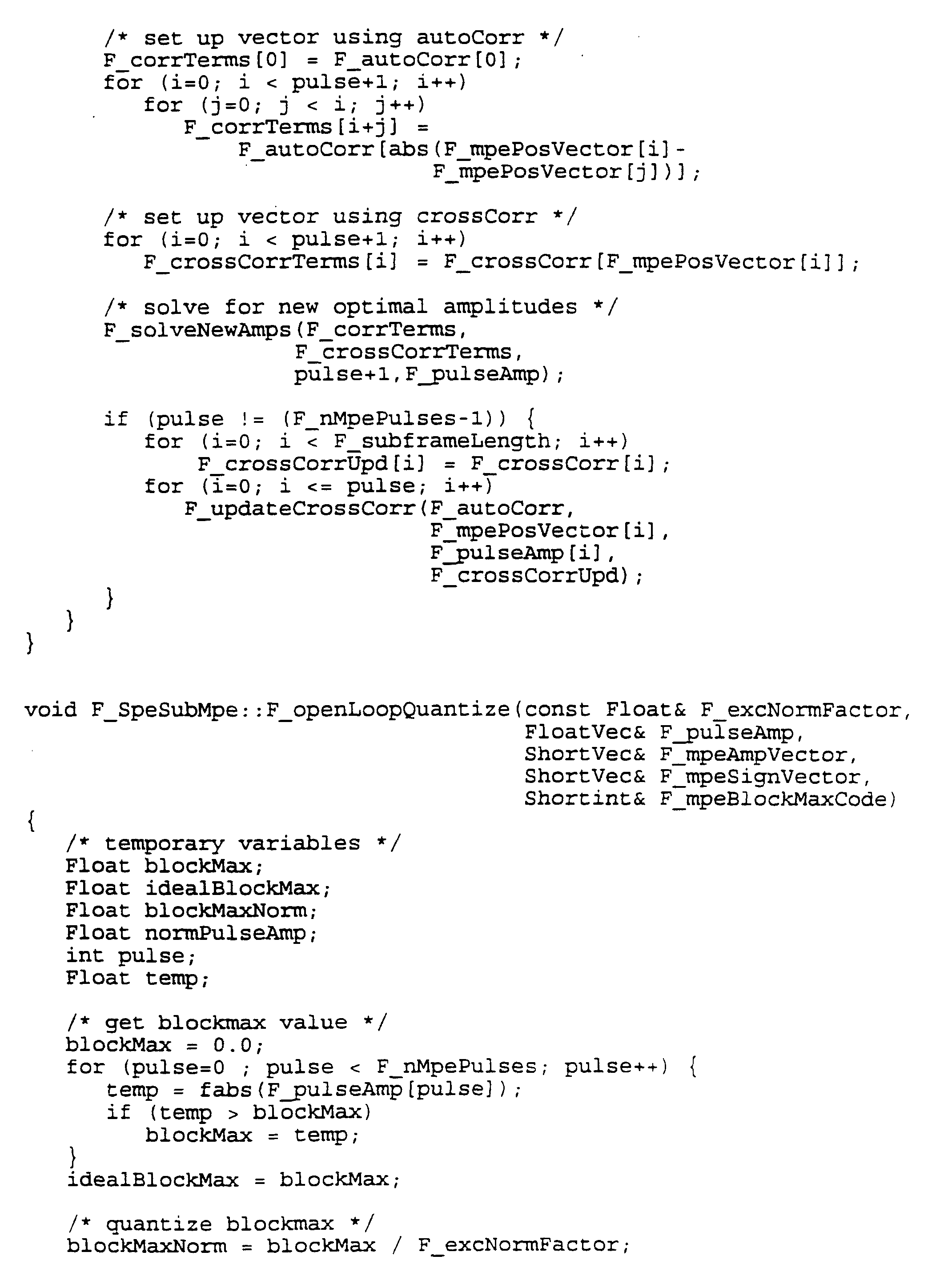
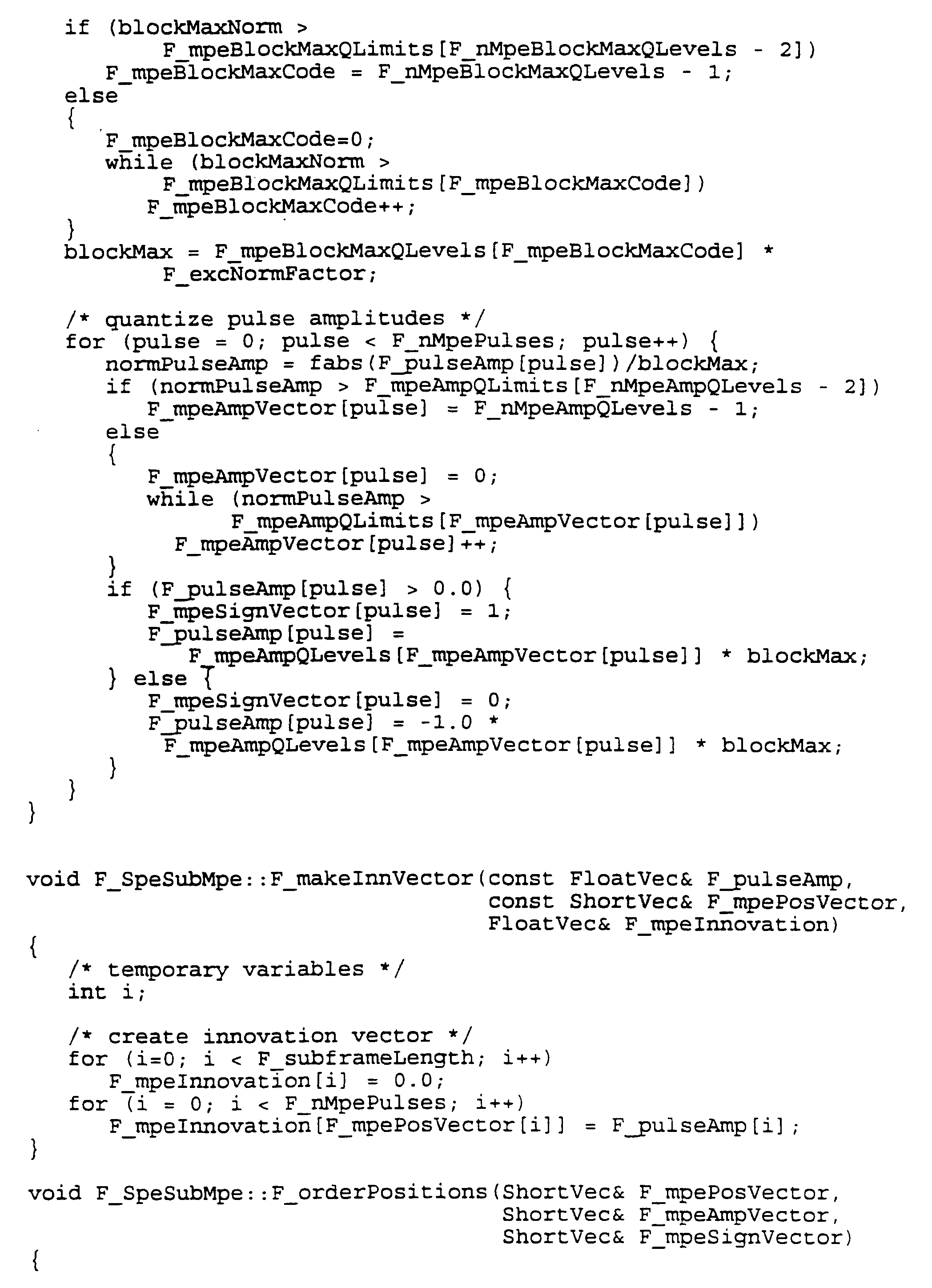
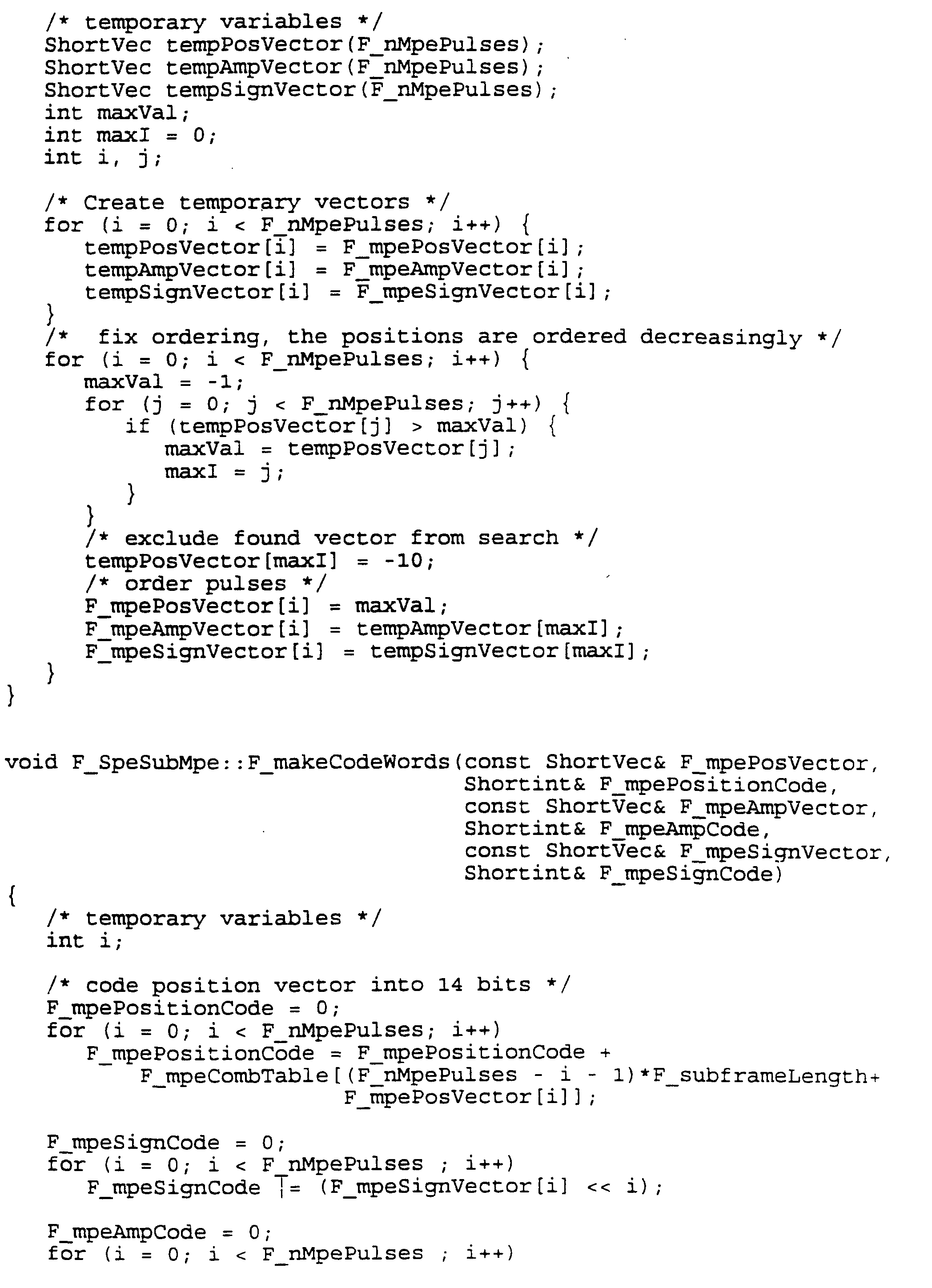
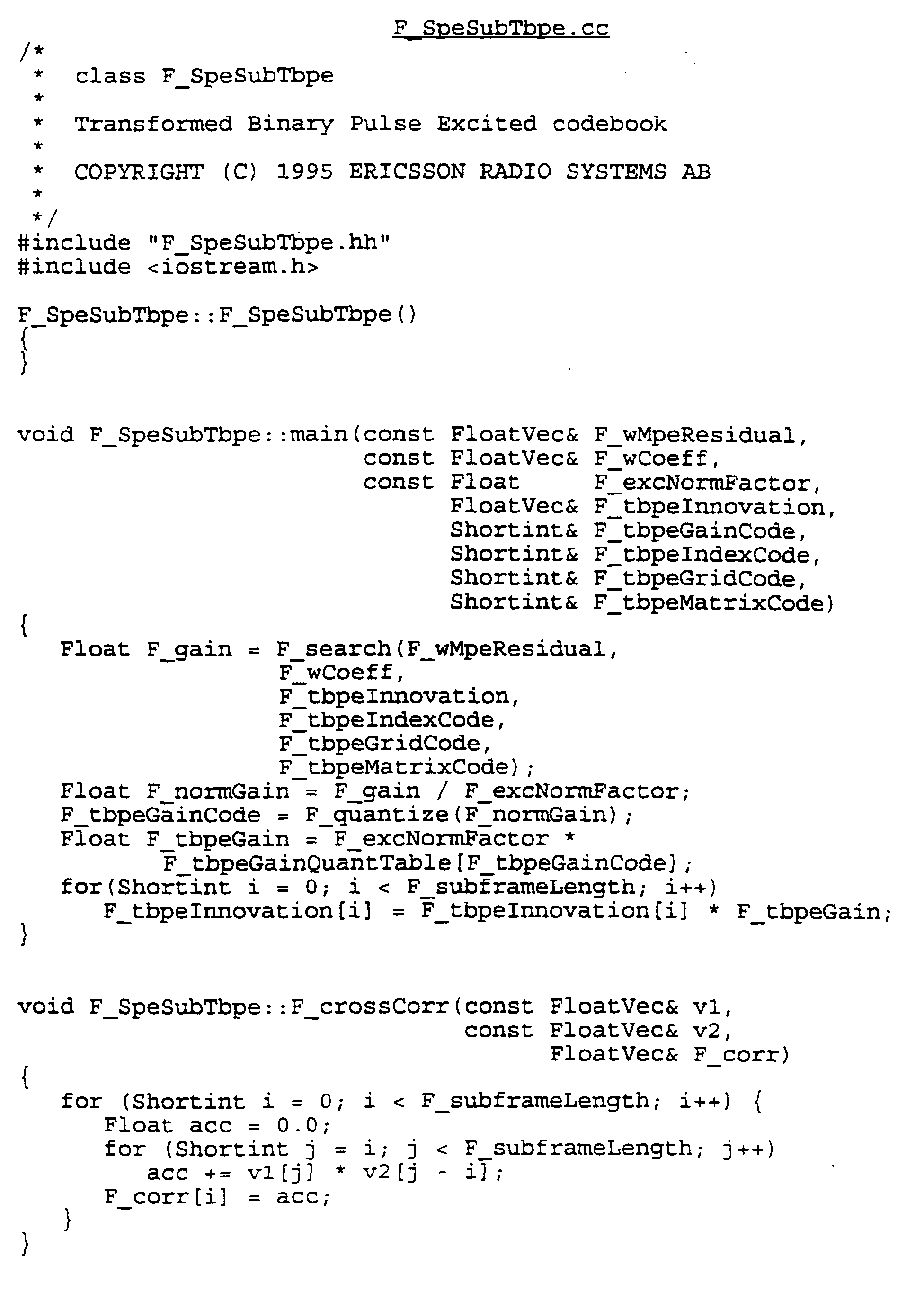
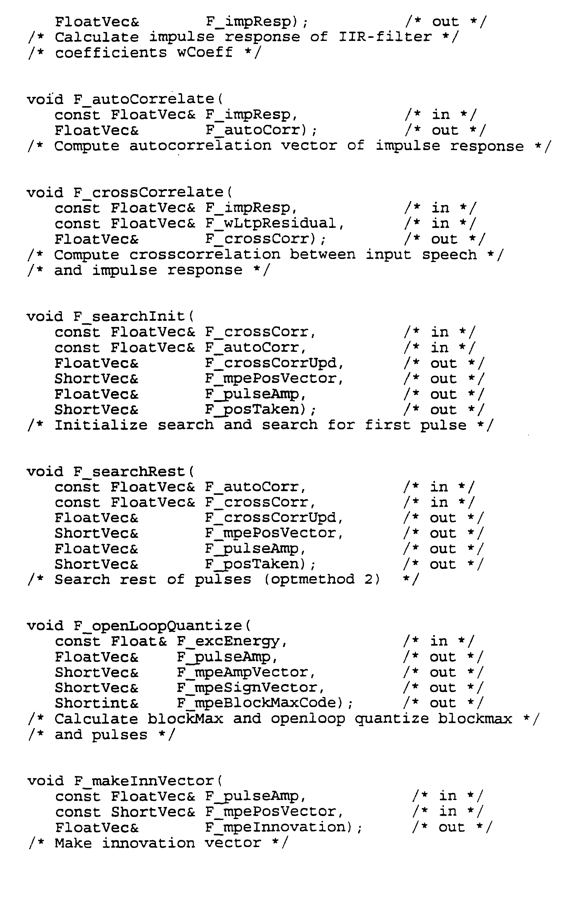
- the algorithm contains all parts that are relevant in a speech encoder.
- the algorithm consists of six main sections.
- the MPE and TBPE sections, which constitute the mixed excitation are expanded to show the contents of the mixed excitation structure analysis.
- One frame based section e.g. for each 160 sample frame, is the LPC analysis section, which calculates and quantizes the short-term synthesis filter.
- the remaining five sections are sub-frame based, e.g. they are performed for each 40 sample sub-frame. The first of these is the sub-frame preprocessing, i.e. parameter extraction; the second is the long-term analysis or adaptive code book analysis; the third is the MPE analysis; the fourth is the TBPE analysis; and the fifth is the state update.
- Multi-pulse excitation MPE
- MPE Multi-pulse excitation
- TBPE Transformed binary pulse excitation
- This APPENDIX summarizes an algorithm for determining the best adaptive code book index i and the corresponding gain g i in an exhaustive search. The signals are also shown in Fig. 1.
Landscapes
- Engineering & Computer Science (AREA)
- Computational Linguistics (AREA)
- Health & Medical Sciences (AREA)
- Audiology, Speech & Language Pathology (AREA)
- Human Computer Interaction (AREA)
- Physics & Mathematics (AREA)
- Acoustics & Sound (AREA)
- Multimedia (AREA)
- Signal Processing (AREA)
- Compression, Expansion, Code Conversion, And Decoders (AREA)
- Reduction Or Emphasis Of Bandwidth Of Signals (AREA)
Description
- FIGURE 1
- is a block diagram of a typical analysis-by-synthesis linear predictive speech coder;
- FIGURE 2
- illustrates the principles of multi-pulse excitation (MPE);
- FIGURE 3
- illustrates a bit allocation scheme for a multi-pulse excitation;
- FIGURE 4
- is a diagram illustrating the bit error sensitivity of the multi-pulse excitation defined in Figure 3;
- FIGURE 5
- a-e illustrates the principles of phase position coded multi-pulse excitation;
- FIGURE 6a
- illustrates the principles of transformed binary pulse excitation (TBPE);
- FIGURE 6b
- illustrates TBPE for a special case of only two pulses;
- FIGURE 7
- illustrates a bit allocation scheme for a transformed binary pulse excitation;
- FIGURE 8
- is a diagram illustrating the bit error sensitivity of the transformed binary pulse excitation;
- FIGURE 9
- illustrates a bit allocation scheme for a combined multi-pulse and transformed binary pulse excitation in accordance with a preferred embodiment of the present invention;
- FIGURE 10
- is a diagram illustrating the bit error sensitivity of the combined multi-pulse and transformed binary pulse excitation in accordance with a preferred embodiment of the present invention;
- FIGURE 11
- compares the bit error sensitivities illustrated in Figures 4, 8 and 10, sorted by bit error sensitivity; and
- FIGURE 12
- is a block diagram of a preferred embodiment of a speech coder in accordance with the present invention.
Subframe preprocessing
LTP analysis (adaptive code book search)
Multi-pulse excitation (MPE)
Calculate impulse response of weighting filter
Calculate autocorrelation function of impulse response
Calculate cross correlation function between impulse response and weighted residual after LTP analysis
Search MPE positions and amplitudes
Quantize amplitudes and block gain
Make MPE innovation vector
Form position code words
Form new weighted residual after MPE analysis
Transformed binary pulse excitation (TBPE)
Calculate impulse response of weighting filter
Calculate cross correlation function between impulse response and weighted residual after MPE analysis
For each matrix do
For each grid do
Calculate matrix cross correlation function
Approximate pulses with sign of cross correlation function
Form weighted TBPE innovation and compare
Form TBPE code words
Quantize TBPE gain
Form TBPE innovation vector
State update
- ex(n) = p(n)
- Excitation vector (f(n) = 0)
- p(n) = gi·ai (n)
- Scaled adaptive code book vector
- s and(n) = h(n)*p(n)
- Synthetic speech
(* = convolution) - e(n) = s(n) - s and(n)
- Error vector
- ew(n) = w(n)*(s(n) - s and(n))
- Weighted error
- E = Σ[ew(n)]2 n=0..N-1
- Squared weighted error
- N = 40 (for example)
- Vector length
- sw(n) = w(n)*s(n)
- Weighted speech
- hw (n) = w(n)*h(n)
- Weighted impulse response for synthesis filter







A class of analysis-by-synthesis predictive coders for high quality speech coding at rates between 4.6 and 16 kbit/s.
IEEE Jour. Sel. Areas Com., Vol. SAC-6, No. 2, Feb. 1988.
Low-delay hybrid vector excitation linear predictive speech coding
Electronics letters Vol. 29 no. 25 1993
Code-excited linear prediction using a mixed source model
Proc. ASSP DSP workshop, 1986
Ultra-fast CELP coding using deterministic multi-codebook innovations.
IEEE ICASSP-92, San Francisco, 1992.
Mixed excitation celp coder.
Eurospeech-89, Paris, Sep. 1989.
A hybrid speech coding based on multi-pulse and CELP at 3.2 kb/s.
IEEE ICASSP-90 ,Albuquerque, 1990.
4800 and 7200 bit/sec hybrid codebook multipulse coding.
IEEE ICASSP-89, Glasgow, 1989
Hybrid switched multi-pulse/stochastic speech coding technique.
US Patent # 5060269
A new model of LPC excitation for producing natural--sounding speech at low bit rates.
IEEE ICASSP-82, Paris, 1982.
A regular-pulse excited linear predictive codec.
Binary code excited linear prediction (BCELP): New approach to celp coding of speech without codebooks.
Electronics letters, vol. 25 no. 6 march 1989.
Binary pulse excitation: A novel approach to low complexity CELP coding.
Kluwer Academic Pub., Advances in speech coding, 1991.
Vector sum excited linear prediction (VSELP).
Kluwer Academic Pub., Advances in speech coding, 1991.
Robust celp coders for noisy backgrounds and noisy channels.
IEEE ICASSP-89, Glasgow, 1989.
Error control and index assignment for speech codecs.
Kluwer Academic Press, 1993.
Excitation pulse positioning method in a linear predictive speech coder.
US Patent # 5193140
Claims (5)
- An analysis-by-synthesis linear predictive speech coder with a synthesis part comprising means (34) for generating a multi-pulse excitation (MPE) for a block of input speech signal, characterized by said synthesis part further comprisingmeans (36) for generating a transformed binary pulse excitation (TBPE) for the same block of input speech signal; andmeans (38) for generating robust speech excitation code by combining said multi-pulse excitation and said transformed binary pulse excitation.
- The speech coder of claim 1, characterized by said multi-pulse excitation (MPE) generating means (34) comprising means for generating pulses in restricted pulse positions.
- The speech coder of claim 2, characterized by said multi-pulse excitation (MPE) generating means (34) comprising means for phase position coding.
- The speech coder of claim 1, 2 or 3, characterized by said synthesis part further comprising an adaptive code book (14) for generating an adaptive excitation.
- The speech coder of claim 4, characterized by means (18, 38; gI, gM, gT) for combining said multi-pulse (MPE), transformed binary pulse (TBPE) and adaptive excitations.
Applications Claiming Priority (3)
| Application Number | Priority Date | Filing Date | Title |
|---|---|---|---|
| SE9501026 | 1995-03-22 | ||
| SE9501026A SE506379C3 (en) | 1995-03-22 | 1995-03-22 | Lpc speech encoder with combined excitation |
| PCT/SE1996/000296 WO1996029696A1 (en) | 1995-03-22 | 1996-03-06 | Analysis-by-synthesis linear predictive speech coder |
Publications (2)
| Publication Number | Publication Date |
|---|---|
| EP0815554A1 EP0815554A1 (en) | 1998-01-07 |
| EP0815554B1 true EP0815554B1 (en) | 2001-06-13 |
Family
ID=20397640
Family Applications (1)
| Application Number | Title | Priority Date | Filing Date |
|---|---|---|---|
| EP96908412A Expired - Lifetime EP0815554B1 (en) | 1995-03-22 | 1996-03-06 | Analysis-by-synthesis linear predictive speech coder |
Country Status (11)
| Country | Link |
|---|---|
| US (1) | US5991717A (en) |
| EP (1) | EP0815554B1 (en) |
| JP (1) | JP3841224B2 (en) |
| KR (1) | KR100368897B1 (en) |
| AU (1) | AU699787B2 (en) |
| CA (1) | CA2214672C (en) |
| DE (1) | DE69613360T2 (en) |
| ES (1) | ES2162038T3 (en) |
| RU (1) | RU2163399C2 (en) |
| SE (1) | SE506379C3 (en) |
| WO (1) | WO1996029696A1 (en) |
Families Citing this family (40)
| Publication number | Priority date | Publication date | Assignee | Title |
|---|---|---|---|---|
| FI955266A7 (en) * | 1995-11-02 | 1997-05-03 | Nokia Corp | Method and apparatus for transmitting messages in a telecommunications system |
| JP3199020B2 (en) * | 1998-02-27 | 2001-08-13 | 日本電気株式会社 | Audio music signal encoding device and decoding device |
| FI113571B (en) * | 1998-03-09 | 2004-05-14 | Nokia Corp | speech Coding |
| FR2776447B1 (en) * | 1998-03-23 | 2000-05-12 | Comsis | JOINT SOURCE-CHANNEL ENCODING IN BLOCKS |
| EP1002237B1 (en) * | 1998-06-09 | 2011-08-10 | Panasonic Corporation | Speech coding and speech decoding |
| SE521225C2 (en) | 1998-09-16 | 2003-10-14 | Ericsson Telefon Ab L M | Method and apparatus for CELP encoding / decoding |
| US6292917B1 (en) * | 1998-09-30 | 2001-09-18 | Agere Systems Guardian Corp. | Unequal error protection for digital broadcasting using channel classification |
| JP4008607B2 (en) * | 1999-01-22 | 2007-11-14 | 株式会社東芝 | Speech encoding / decoding method |
| US7272553B1 (en) * | 1999-09-08 | 2007-09-18 | 8X8, Inc. | Varying pulse amplitude multi-pulse analysis speech processor and method |
| WO2001022676A1 (en) * | 1999-09-21 | 2001-03-29 | Comsis | Block joint source-channel coding |
| US6529867B2 (en) * | 2000-09-15 | 2003-03-04 | Conexant Systems, Inc. | Injecting high frequency noise into pulse excitation for low bit rate CELP |
| SE519976C2 (en) * | 2000-09-15 | 2003-05-06 | Ericsson Telefon Ab L M | Coding and decoding of signals from multiple channels |
| SE0004818D0 (en) * | 2000-12-22 | 2000-12-22 | Coding Technologies Sweden Ab | Enhancing source coding systems by adaptive transposition |
| FI119955B (en) * | 2001-06-21 | 2009-05-15 | Nokia Corp | Method, encoder and apparatus for speech coding in an analysis-through-synthesis speech encoder |
| CA2415105A1 (en) * | 2002-12-24 | 2004-06-24 | Voiceage Corporation | A method and device for robust predictive vector quantization of linear prediction parameters in variable bit rate speech coding |
| RU2248619C2 (en) * | 2003-02-12 | 2005-03-20 | Рыболовлев Александр Аркадьевич | Method and device for converting speech signal by method of linear prediction with adaptive distribution of information resources |
| KR20050028193A (en) * | 2003-09-17 | 2005-03-22 | 삼성전자주식회사 | Method for adaptively inserting additional information into audio signal and apparatus therefor, method for reproducing additional information inserted in audio data and apparatus therefor, and recording medium for recording programs for realizing the same |
| DE102004007185B3 (en) * | 2004-02-13 | 2005-06-30 | Fraunhofer-Gesellschaft zur Förderung der angewandten Forschung e.V. | Predictive coding method for information signals using adaptive prediction algorithm with switching between higher adaption rate and lower prediction accuracy and lower adaption rate and higher prediction accuracy |
| KR20070029751A (en) * | 2004-06-22 | 2007-03-14 | 코닌클리케 필립스 일렉트로닉스 엔.브이. | Audio encoding and decoding |
| DE102005000830A1 (en) * | 2005-01-05 | 2006-07-13 | Siemens Ag | Bandwidth extension method |
| US7610195B2 (en) * | 2006-06-01 | 2009-10-27 | Nokia Corporation | Decoding of predictively coded data using buffer adaptation |
| RU2319222C1 (en) * | 2006-08-30 | 2008-03-10 | Валерий Юрьевич Тарасов | Method for encoding and decoding speech signal using linear prediction method |
| US20120045001A1 (en) * | 2008-08-13 | 2012-02-23 | Shaohua Li | Method of Generating a Codebook |
| RU2400832C2 (en) * | 2008-11-24 | 2010-09-27 | Государственное образовательное учреждение высшего профессионального образования Академия Федеральной службы охраны Российской Федерации (Академия ФCО России) | Method for generation of excitation signal in low-speed vocoders with linear prediction |
| US9236063B2 (en) | 2010-07-30 | 2016-01-12 | Qualcomm Incorporated | Systems, methods, apparatus, and computer-readable media for dynamic bit allocation |
| US9208792B2 (en) | 2010-08-17 | 2015-12-08 | Qualcomm Incorporated | Systems, methods, apparatus, and computer-readable media for noise injection |
| KR101699898B1 (en) | 2011-02-14 | 2017-01-25 | 프라운호퍼 게젤샤프트 쭈르 푀르데룽 데어 안겐반텐 포르슝 에. 베. | Apparatus and method for processing a decoded audio signal in a spectral domain |
| SG192714A1 (en) | 2011-02-14 | 2013-09-30 | Fraunhofer Ges Forschung | Apparatus and method for coding a portion of an audio signal using a transient detection and a quality result |
| PL2661745T3 (en) | 2011-02-14 | 2015-09-30 | Fraunhofer Ges Forschung | Apparatus and method for error concealment in low-delay unified speech and audio coding (usac) |
| CN103477387B (en) | 2011-02-14 | 2015-11-25 | 弗兰霍菲尔运输应用研究公司 | Linear Prediction-Based Coding Schemes Using Spectral-Domain Noise Shaping |
| MY159444A (en) | 2011-02-14 | 2017-01-13 | Fraunhofer-Gesellschaft Zur Forderung Der Angewandten Forschung E V | Encoding and decoding of pulse positions of tracks of an audio signal |
| AU2012217184B2 (en) * | 2011-02-14 | 2015-07-30 | Fraunhofer-Gesellschaft Zur Foerderung Der Angewandten Forschung E. V. | Encoding and decoding of pulse positions of tracks of an audio signal |
| CN102959620B (en) | 2011-02-14 | 2015-05-13 | 弗兰霍菲尔运输应用研究公司 | Information signal representation using lapped transform |
| RU2586838C2 (en) | 2011-02-14 | 2016-06-10 | Фраунхофер-Гезелльшафт Цур Фердерунг Дер Ангевандтен Форшунг Е.Ф. | Audio codec using synthetic noise during inactive phase |
| TWI563498B (en) | 2011-02-14 | 2016-12-21 | Fraunhofer Ges Forschung | Apparatus and method for encoding an audio signal using an aligned look-ahead portion, and related computer program |
| RU2495504C1 (en) * | 2012-06-25 | 2013-10-10 | Государственное казенное образовательное учреждение высшего профессионального образования Академия Федеральной службы охраны Российской Федерации (Академия ФСО России) | Method of reducing transmission rate of linear prediction low bit rate voders |
| EP2981961B1 (en) * | 2013-04-05 | 2017-05-10 | Dolby International AB | Advanced quantizer |
| KR102383819B1 (en) * | 2013-04-05 | 2022-04-08 | 돌비 인터네셔널 에이비 | Audio encoder and decoder |
| RU2631968C2 (en) * | 2015-07-08 | 2017-09-29 | Федеральное государственное казенное военное образовательное учреждение высшего образования "Академия Федеральной службы охраны Российской Федерации" (Академия ФСО России) | Method of low-speed coding and decoding speech signal |
| TWI723545B (en) * | 2019-09-17 | 2021-04-01 | 宏碁股份有限公司 | Speech processing method and device thereof |
Family Cites Families (9)
| Publication number | Priority date | Publication date | Assignee | Title |
|---|---|---|---|---|
| NL8500843A (en) * | 1985-03-22 | 1986-10-16 | Koninkl Philips Electronics Nv | MULTIPULS EXCITATION LINEAR-PREDICTIVE VOICE CODER. |
| CA1323934C (en) * | 1986-04-15 | 1993-11-02 | Tetsu Taguchi | Speech processing apparatus |
| GB8621932D0 (en) * | 1986-09-11 | 1986-10-15 | British Telecomm | Speech coding |
| CA1337217C (en) * | 1987-08-28 | 1995-10-03 | Daniel Kenneth Freeman | Speech coding |
| CA2032520C (en) * | 1989-05-11 | 1996-09-17 | Tor Bjorn Minde | Excitation pulse positioning method in a linear predictive speech coder |
| US4980916A (en) * | 1989-10-26 | 1990-12-25 | General Electric Company | Method for improving speech quality in code excited linear predictive speech coding |
| US5195168A (en) * | 1991-03-15 | 1993-03-16 | Codex Corporation | Speech coder and method having spectral interpolation and fast codebook search |
| JPH0612098A (en) * | 1992-03-16 | 1994-01-21 | Sanyo Electric Co Ltd | Speech coding device |
| JP3328080B2 (en) * | 1994-11-22 | 2002-09-24 | 沖電気工業株式会社 | Code-excited linear predictive decoder |
-
1995
- 1995-03-22 SE SE9501026A patent/SE506379C3/en not_active IP Right Cessation
-
1996
- 1996-03-06 WO PCT/SE1996/000296 patent/WO1996029696A1/en not_active Ceased
- 1996-03-06 ES ES96908412T patent/ES2162038T3/en not_active Expired - Lifetime
- 1996-03-06 JP JP52832596A patent/JP3841224B2/en not_active Expired - Lifetime
- 1996-03-06 EP EP96908412A patent/EP0815554B1/en not_active Expired - Lifetime
- 1996-03-06 CA CA002214672A patent/CA2214672C/en not_active Expired - Lifetime
- 1996-03-06 KR KR1019970706601A patent/KR100368897B1/en not_active Expired - Lifetime
- 1996-03-06 RU RU97117357/09A patent/RU2163399C2/en active
- 1996-03-06 AU AU51654/96A patent/AU699787B2/en not_active Expired
- 1996-03-06 DE DE69613360T patent/DE69613360T2/en not_active Expired - Lifetime
-
1997
- 1997-09-05 US US08/924,877 patent/US5991717A/en not_active Expired - Lifetime
Also Published As
| Publication number | Publication date |
|---|---|
| SE506379C3 (en) | 1998-01-19 |
| ES2162038T3 (en) | 2001-12-16 |
| SE506379C2 (en) | 1997-12-08 |
| WO1996029696A1 (en) | 1996-09-26 |
| CA2214672C (en) | 2005-07-05 |
| SE9501026D0 (en) | 1995-03-22 |
| DE69613360D1 (en) | 2001-07-19 |
| AU5165496A (en) | 1996-10-08 |
| JPH11502318A (en) | 1999-02-23 |
| US5991717A (en) | 1999-11-23 |
| SE9501026L (en) | 1996-09-23 |
| RU2163399C2 (en) | 2001-02-20 |
| JP3841224B2 (en) | 2006-11-01 |
| CA2214672A1 (en) | 1996-09-26 |
| DE69613360T2 (en) | 2001-10-11 |
| KR19980703198A (en) | 1998-10-15 |
| KR100368897B1 (en) | 2003-04-11 |
| AU699787B2 (en) | 1998-12-17 |
| EP0815554A1 (en) | 1998-01-07 |
Similar Documents
| Publication | Publication Date | Title |
|---|---|---|
| US5991717A (en) | Analysis-by-synthesis linear predictive speech coder with restricted-position multipulse and transformed binary pulse excitation | |
| KR100264863B1 (en) | Method for speech coding based on a celp model | |
| US6141638A (en) | Method and apparatus for coding an information signal | |
| US5293449A (en) | Analysis-by-synthesis 2,4 kbps linear predictive speech codec | |
| US5138661A (en) | Linear predictive codeword excited speech synthesizer | |
| US6345248B1 (en) | Low bit-rate speech coder using adaptive open-loop subframe pitch lag estimation and vector quantization | |
| KR20020077389A (en) | Indexing pulse positions and signs in algebraic codebooks for coding of wideband signals | |
| KR20010024935A (en) | Speech coding | |
| EP0824750B1 (en) | A gain quantization method in analysis-by-synthesis linear predictive speech coding | |
| AU719568B2 (en) | Method for searching an excitation codebook in a code excited linear prediction (CELP) coder | |
| EP0773533B1 (en) | Method of synthesizing a block of a speech signal in a CELP-type coder | |
| Salami et al. | 8 kbit/s ACELP coding of speech with 10 ms speech-frame: A candidate for CCITT standardization | |
| EP0578436B1 (en) | Selective application of speech coding techniques | |
| KR100465316B1 (en) | Speech encoder and speech encoding method thereof | |
| US7337110B2 (en) | Structured VSELP codebook for low complexity search | |
| CA2336360C (en) | Speech coder | |
| Salami | Binary pulse excitation: A novel approach to low complexity CELP coding | |
| Ofer et al. | A unified framework for LPC excitation representation in residual speech coders | |
| Ramirez et al. | A multistage search of algebraic CELP codebooks | |
| EP0539103B1 (en) | Generalized analysis-by-synthesis speech coding method and apparatus | |
| Akamine et al. | CELP coding with an adaptive density pulse excitation model | |
| JP3103108B2 (en) | Audio coding device | |
| JP3284874B2 (en) | Audio coding device | |
| KR20010073146A (en) | Method and apparatus for coding an information signal | |
| HK1090465B (en) | Method and apparatus for the generation of vectors for speech decoding& x9;& x9;& x9;& x9;& x9; |
Legal Events
| Date | Code | Title | Description |
|---|---|---|---|
| PUAI | Public reference made under article 153(3) epc to a published international application that has entered the european phase |
Free format text: ORIGINAL CODE: 0009012 |
|
| 17P | Request for examination filed |
Effective date: 19970816 |
|
| AK | Designated contracting states |
Kind code of ref document: A1 Designated state(s): DE ES FI GB IT |
|
| 17Q | First examination report despatched |
Effective date: 19981108 |
|
| GRAG | Despatch of communication of intention to grant |
Free format text: ORIGINAL CODE: EPIDOS AGRA |
|
| RIC1 | Information provided on ipc code assigned before grant |
Free format text: 7G 10L 19/10 A |
|
| GRAG | Despatch of communication of intention to grant |
Free format text: ORIGINAL CODE: EPIDOS AGRA |
|
| GRAH | Despatch of communication of intention to grant a patent |
Free format text: ORIGINAL CODE: EPIDOS IGRA |
|
| GRAH | Despatch of communication of intention to grant a patent |
Free format text: ORIGINAL CODE: EPIDOS IGRA |
|
| GRAA | (expected) grant |
Free format text: ORIGINAL CODE: 0009210 |
|
| AK | Designated contracting states |
Kind code of ref document: B1 Designated state(s): DE ES FI GB IT |
|
| REF | Corresponds to: |
Ref document number: 69613360 Country of ref document: DE Date of ref document: 20010719 |
|
| ITF | It: translation for a ep patent filed | ||
| REG | Reference to a national code |
Ref country code: ES Ref legal event code: FG2A Ref document number: 2162038 Country of ref document: ES Kind code of ref document: T3 |
|
| REG | Reference to a national code |
Ref country code: GB Ref legal event code: IF02 |
|
| PLBE | No opposition filed within time limit |
Free format text: ORIGINAL CODE: 0009261 |
|
| STAA | Information on the status of an ep patent application or granted ep patent |
Free format text: STATUS: NO OPPOSITION FILED WITHIN TIME LIMIT |
|
| 26N | No opposition filed | ||
| PGFP | Annual fee paid to national office [announced via postgrant information from national office to epo] |
Ref country code: ES Payment date: 20150326 Year of fee payment: 20 Ref country code: DE Payment date: 20150327 Year of fee payment: 20 Ref country code: IT Payment date: 20150325 Year of fee payment: 20 Ref country code: FI Payment date: 20150327 Year of fee payment: 20 |
|
| PGFP | Annual fee paid to national office [announced via postgrant information from national office to epo] |
Ref country code: GB Payment date: 20150327 Year of fee payment: 20 |
|
| REG | Reference to a national code |
Ref country code: DE Ref legal event code: R071 Ref document number: 69613360 Country of ref document: DE |
|
| REG | Reference to a national code |
Ref country code: GB Ref legal event code: PE20 Expiry date: 20160305 |
|
| PG25 | Lapsed in a contracting state [announced via postgrant information from national office to epo] |
Ref country code: GB Free format text: LAPSE BECAUSE OF EXPIRATION OF PROTECTION Effective date: 20160305 |
|
| REG | Reference to a national code |
Ref country code: ES Ref legal event code: FD2A Effective date: 20160624 |
|
| PG25 | Lapsed in a contracting state [announced via postgrant information from national office to epo] |
Ref country code: ES Free format text: LAPSE BECAUSE OF EXPIRATION OF PROTECTION Effective date: 20160307 |