EP0815341B1 - Dual bore riser - Google Patents
Dual bore riser Download PDFInfo
- Publication number
- EP0815341B1 EP0815341B1 EP96904176A EP96904176A EP0815341B1 EP 0815341 B1 EP0815341 B1 EP 0815341B1 EP 96904176 A EP96904176 A EP 96904176A EP 96904176 A EP96904176 A EP 96904176A EP 0815341 B1 EP0815341 B1 EP 0815341B1
- Authority
- EP
- European Patent Office
- Prior art keywords
- riser
- tubing
- coiled tubing
- bore
- well
- Prior art date
- Legal status (The legal status is an assumption and is not a legal conclusion. Google has not performed a legal analysis and makes no representation as to the accuracy of the status listed.)
- Expired - Lifetime
Links
- 230000009977 dual effect Effects 0.000 title claims description 47
- 238000000034 method Methods 0.000 claims description 18
- 230000008878 coupling Effects 0.000 claims description 16
- 238000010168 coupling process Methods 0.000 claims description 16
- 238000005859 coupling reaction Methods 0.000 claims description 16
- 238000004519 manufacturing process Methods 0.000 claims description 12
- 238000004891 communication Methods 0.000 claims description 4
- 238000009434 installation Methods 0.000 claims description 3
- 230000000452 restraining effect Effects 0.000 claims description 3
- 238000005520 cutting process Methods 0.000 claims description 2
- 238000003860 storage Methods 0.000 description 6
- 241000191291 Abies alba Species 0.000 description 4
- 241000239290 Araneae Species 0.000 description 3
- 230000004888 barrier function Effects 0.000 description 3
- 230000008901 benefit Effects 0.000 description 3
- 239000012530 fluid Substances 0.000 description 2
- 238000002955 isolation Methods 0.000 description 2
- 230000009467 reduction Effects 0.000 description 2
- 238000005452 bending Methods 0.000 description 1
- 230000015572 biosynthetic process Effects 0.000 description 1
- 230000008859 change Effects 0.000 description 1
- 238000010586 diagram Methods 0.000 description 1
- 230000008030 elimination Effects 0.000 description 1
- 238000003379 elimination reaction Methods 0.000 description 1
- 238000002347 injection Methods 0.000 description 1
- 239000007924 injection Substances 0.000 description 1
- 239000007788 liquid Substances 0.000 description 1
- 230000013011 mating Effects 0.000 description 1
- 239000002184 metal Substances 0.000 description 1
- 238000012986 modification Methods 0.000 description 1
- 230000004048 modification Effects 0.000 description 1
- 230000001105 regulatory effect Effects 0.000 description 1
- XLYOFNOQVPJJNP-UHFFFAOYSA-N water Substances O XLYOFNOQVPJJNP-UHFFFAOYSA-N 0.000 description 1
Images





Classifications
-
- E—FIXED CONSTRUCTIONS
- E21—EARTH OR ROCK DRILLING; MINING
- E21B—EARTH OR ROCK DRILLING; OBTAINING OIL, GAS, WATER, SOLUBLE OR MELTABLE MATERIALS OR A SLURRY OF MINERALS FROM WELLS
- E21B19/00—Handling rods, casings, tubes or the like outside the borehole, e.g. in the derrick; Apparatus for feeding the rods or cables
- E21B19/22—Handling reeled pipe or rod units, e.g. flexible drilling pipes
-
- E—FIXED CONSTRUCTIONS
- E21—EARTH OR ROCK DRILLING; MINING
- E21B—EARTH OR ROCK DRILLING; OBTAINING OIL, GAS, WATER, SOLUBLE OR MELTABLE MATERIALS OR A SLURRY OF MINERALS FROM WELLS
- E21B17/00—Drilling rods or pipes; Flexible drill strings; Kellies; Drill collars; Sucker rods; Cables; Casings; Tubings
- E21B17/01—Risers
Definitions
- the present invention relates to a dual bore riser for use in sub-sea production or water or gas injection systems.
- a conventional dual bore riser system consists of a large number of parts which require to be assembled during run-in. At the present time the cost of a conventional dual bore riser costs approximately £1,000 per foot and requires significant storage space which is normally limited on off-shore vessels. When such a conventional riser is run, it requires a considerable amount of specialised equipment for handling and make-up such as spiders etc. This has an impact in terms of both purchase cost and increased running times.
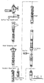
- Fig. 1 shows an exploded view of the principal parts of a conventional dual parallel bore riser system. It will be seen that approximately ten parts shown, the surface tree, a riser handling spider, a surface tree adaptor joint, a riser tensioning joint, a standard riser joint and a riser handling test tool, a dual parallel bcre riser joint adaptor which is approximately 40 ft. long, an orientation joint, it will be seen from this drawing that the entire structure is relatively complex and includes the assembly of a considerable number of prefabricated components which, as outlined above, require significant storage space which is normally limited on off-shore vessels.
- An object of the present invention is to obviate or mitigate at least one of the aforementioned disadvantages.
- a further object of the present invention is to provide an improved dual bore riser which is relatively less expensive to purchase and to run and which requires significantly less storage space than a conventional riser system.
- a further object of the present invention is to obviate the requirement for specialised handling equipment and make-up of the dual bore riser.
- a dual bore riser system which comprises a conventional monobore riser for production access and a independent coil tubing disposed in parallel with the monobore riser for providing access into the annular space between production coiling and production tubing.
- the monobore riser comprises discrete joints of tubing, casing or drill pipe and the coil tubing riser which may be any size of coiled tubing but normally between 23 ⁇ 8" and 27 ⁇ 8" outside diameter.
- the standard monobore riser and coil tubing riser interface with the tubing hanger running tool via a landing spool or adaptor adaptor.
- the coiled tubing is deployed from a storage reel, via a roller sheave and straightening rollers into the well with the tubing riser.
- the coiled tubing is clamped to the tubing riser at intervals along its length corresponding to a joint every 30 ft.
- the upper end of the landing spool or adaptor receives the tubing and also contains a termination for the coiled tubing which is typically a swage device.
- the dual parallel bore landing spool adaptor and landing spool has an outside diameter to fit into the 18%" BOP stack and the landing spool has a smooth outside surface for co-operating with the interior of the annular BOP.
- the monobore and coiled tubing risers may be coupled to one of; a conventional stress joint and riser disconnect package to a sub-sea Christmas tree, a dual bore proprietary tubing hanger or a dual bore test tree which fits beneath the blind/shear rams in the BOP stack in the same manner as disclosed in corresponding International Patent Application WO93/03255.
- a method of running intervention equipment into a well during or after completion comprising:
- the method includes restraining the coiled tubing to the tubing riser at each joint along the length of the tubing riser.
- the dual bore or 5" x 2" completion sub-sea tree has a main bore and a parallel annulus bore, the main bore having at least one operable valve and the annulus bore having at least one operable valve.
- wireline access is possible using the improved dual bore riser by cutting the coiled tubing at the surface and terminating the cut tubing to a frame and valve assembly which is clamped to a conventional surface tree.
- the method is such that the frame allows the coiled tubing to be pretensioned, therefore avoiding the requirement for an accurate termination of the coiled tubing and compensating for any changes in overall length between the two riser strings.
- the coiled tubing may be left on the reel thereby providing annulus communication through the tubing on the reel via a conventional slip ring assembly.
- an improved dual bore riser for coupling to intervention well equipment prior to the installation of a sub-sea production tree, said improved dual bore riser comprising:
- the second coiled tubing riser is coupled to the first tubing riser at every riser joint along its length.
- the well tool run is a 5" x 2" completion sub-sea test tree.
- the well tool may be any other suitable well intervention equipment tool.
- the coiled tubing is coupled to a landing spool disposed between the riser and the completion test tree.
- the coiled tubing is coupled to the landing spool via swage and quick connector system and the tubing riser is coupled to the landing spool via a landing spool adaptor.
- a method of forming a dual bore riser for running well intervention equipment comprising the steps of:
- Fig. 2 of the drawings depicts the layout of a tubing landing string 10 in accordance with an embodiment of the present invention.
- the string 10 mainly consists of a 51 ⁇ 2" premium tubing riser 12 and a coiled tubing annulus riser 14 which is coupled to the tubing riser 12 at various spaced locations along the length of the riser 10 by restraining clamps 16.
- An umbilical 18 is also coupled to the riser 10 via the clamps 16.
- the riser contains a lubricator valve 20 at its upper end and retainer valve 22 at an intermediate position and a dual bore sub-sea test tree 24 is located at its lower position.
- the sub-sea test tree 24 has two ball valves in the main bore and two separate ball valves in the annulus bore.
- the completion test tree 24 is coupled to dual bore tubing hanger running tool 44.
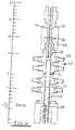
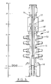
- the tubing riser 12 and coiled tubing 14 are coupled to the dual bore completion tree 24 via the landing spool adaptor 28 best shown in Fig 2 and Fig. 3a.
- the 51 ⁇ 2" tubing riser is received by the landing spool adaptor 28 in a threaded bore 30.
- the coiled tubing 14 is received in a coil tubing terminator 32 using a conventional coiled tubing swage and connector system.
- the landing spool adaptor 28 may receive different sizes of coil tubing and tubing riser although in the drawings shown the tubing riser is a 51 ⁇ 2" and the coil tubing is 27 ⁇ 8".
- the landing spool adaptor is coupled to the landing spool 29 via a connector 36 and it will be seen that the bore 13 of the tubing riser 12 registers with the internal bore 38 of the landing spool 29. Similarly, the internal bore 15 of the coiled tubing registers with the annulus bore 40 of the landing spool to provide communication in the main bore and in the annulus bores.
- Sectional view Fig. 3b taken on the lines X-X of Fig. 3a shows that the main bore 38 offset from the centre of the landing spool, as is annulus bore 40. This arrangement is termed dual bore.
- Fig. 4 of the drawings is a longitudinal sectional view through a BOP stack 42 which contains a tubing landing string layout similar to that shown in Fig. 3a disposed in the bore of the BOP stack 42.
- the riser is coupled to a 5" x 2" sub-sea test tree 24 which, in turn, is coupled to a proprietary tubing hanger running tool 44 such as Cooper or FMC tool and to a proprietary completion tubing hanger 16.
- the landing string layout is spaced out such that the annular BOP 48 can be closed around the exterior of the landing spool 29 to provide an additional annulus barrier if required.
- the space out is such that the completion tree 24 is disposed beneath the blind/shear rams 50 as disclosed in applicant's copending published PCT application WO93/03255.
- tubing riser 10 is substantially identical to that of the 5" section of a standard riser of the type shown in Fig. 1 as far as pressure integrity for the well fluid flow and structural capability to run and retrieve the completion test string is required.
- Fig. 5 of the drawings which is similar to Fig. 4 and which shows a dual bore riser coupled via 5" x 2" completion sub-sea test tree to an Expro test tubing hanger and a production casing hanger.
- the height of the BOP stack shear rams is not critical but the annular BOP must engage the landing string 29.
- like numerals in this figure refer to the same parts as in Fig. 4.
- the coil tubing riser is coupled to the 51 ⁇ 2" tubing riser approximately every 30 ft. which is the length of a tubing riser section.
- the umbilical is also coupled to the 51 ⁇ 2" tubing riser.
- Fig. 6 of the drawings depicts the surface pressure control equipment for a wireline access option into a 2" line for tubing hanger plug retrieval.
- the tubing riser 12 is coupled to a 5" surface flow head 60 which, in turn, is coupled to an elevator sub 62 for a lifting frame and to a wireline stuffing box 64.
- the coiled tubing 14 is coupled to a frame 66 via a swage connection 68.
- the function of the frame 66 is to allow the coil tubing to be pretensioned by exerting a hydraulic force on the dual pistons (65) which is subsequently transferred to the tubing.
- the hydraulic pressure is regulated by the use of a gas/liquid accumulator allowing the pistons to expand and retract and therefore compensate for the subsequent change in length of the dual risers.
- the coiled tubing connection 68 is coupled via a 2" master valve 70 to a T-connection 72 which is has an annular inlet 74 on one leg so that annulus fluids can be pumped through the coiled tubing and the other leg is coupled to a blind cap 76 which can be removed to facilitate wireline entry. It will be appreciated that if no wireline operations are required, the coiled tubing can be left on the reel, thereby providing annulus communications via a conventional slip ring assembly.
- Fig. 7 depicts a conventional coiled tubing reel 78 and tubing 14 is taken from the reel via a curved sheave 80 which includes straightening rollers (not shown) so that the coiled tubing 14 which leaves the sheath is substantially straight and this, in turn, is coupled to the tubing riser 12 as shown in Figs. 3 and 6 by clamp 16 at various locations along its length after first having been coupled to the landing spool adaptor.
- the riser is run by firstly coupling the desired arrangement of intervention tools, such as tubing hanger, running tool and completion test tree together.
- intervention tools such as tubing hanger, running tool and completion test tree
- the landing spool 29 is coupled to the completion sub-sea test tree 24 and the landing spool adaptor 29 is coupled to the landing spool 29.
- these are held at the surface by conventional tongs and then the first section of the 51 ⁇ 2" tubing riser is coupled to the landing spool via bore 30.
- the leading end of the coiled tubing 14 is coupled to the connector 32 by the swage and quick connector system.
- the first part of the riser 10 is formed.
- the intervention assembly and the riser is then lowered and at the next section the coiled tubing is clamped to the tubing riser and also to the umbilical and this is repeated until the riser is of the desired length such that the correct space out is achieved with the landing spool 29 being disposed in the annular BOP 48 and the 5" x 2" completion tree 24 is disposed in the BOP stack 42 such that it is beneath the shear/blind rams 50.
- the equipment can be operated as required from surface to provide appropriate batch completion and clean ups prior to the installation of a sub-sea production tree.
- Fig. 8 it will be seen that the 5" x 2" test tree 24 has an orientation helical cam profile 82 for mating with a BOP pin for correctly orienting tubing hanger running tool 44.
- a completion is run on 51 ⁇ 2" tubing using rig-mounted elevators and coiled tubing from the reel.
- Fig. 9 shows a tubing hanger run 85and landed in the sub-sea wellhead 84 which is located at the bottom of BOP stack 42 and similarly Fig. 10 shows a landing string using 51 ⁇ 2" tubing and coiled tubing coupled to a sub-sea conventional Christmas tree 90.
- the improved dual bore riser in accordance with the present invention provides significant benefit over the existing dual bore risers. Firstly it is substantially less expensive, costing between 10%-20% of the existing system, and uses approximately only 15% of the storage space of conventional dual bore risers which is a considerable advantage in off-shore vessels where storage space is usually very limited.
- the improved dual bore riser does not require specialised equipment such as spiders and the like which minimises cost and reduces running time because the equipment required for the deployment of the riser is identical to that used to deploy the completion.
- the new system offers a considerable reduction in the number of potential leak paths in the annulus system, i.e. from one every 40" because of previous couplings, to one at each termination.
- elastomeric seals are used in the monobore riser and this has been replaced by metal-to-metal connections in the 51 ⁇ 2" tubing riser further improving the reliability of the system.
- coiled tubing termination eliminates compressive coupling normally associated with the proprietary dual bore riser system and this also minimises the bending imparted to the 5.5" tensile structural member.
- the improved dual bore riser in accordance with the present invention has a number of additional advantages. Firstly, it provides additional isolation barriers by incorporating two valves in the 5" x 2" completion sub-sea test tree and the well may be left suspended which provides a subsequent reduction in rig time and formation damage and reduces the role of the BOP to a secondary barrier by avoiding the requirement for the BOP stack to provide annulus isolation.
Landscapes
- Engineering & Computer Science (AREA)
- Geology (AREA)
- Mining & Mineral Resources (AREA)
- Life Sciences & Earth Sciences (AREA)
- General Life Sciences & Earth Sciences (AREA)
- Fluid Mechanics (AREA)
- Mechanical Engineering (AREA)
- Environmental & Geological Engineering (AREA)
- Physics & Mathematics (AREA)
- Geochemistry & Mineralogy (AREA)
- Earth Drilling (AREA)
- Refuge Islands, Traffic Blockers, Or Guard Fence (AREA)
- Amplifiers (AREA)
- Oscillators With Electromechanical Resonators (AREA)
- Optical Integrated Circuits (AREA)
Description
Claims (13)
- A method of running intervention equipment (24,28,29,42) into a well during or after completion, said method comprising:providing well equipment (24,28,29,42) for running into a well,coupling sequential sections of tubing riser (12) to the well equipment,providing a coiled tubing riser (14) of smaller diameter than the tubing riser (12),coupling the coiled tubing riser (14) to said well equipment and feeding the coiled tubing riser (14) with the tubing riser (12) to create a structure such that the tubing riser (12) is adjacent and parallel to the coiled tubing (14),coupling the coiled tubing riser (14) to the tubing riser (12) at a plurality of spaced locations along the length of the riser (12) to create a dual bore riser (12,14), andraising or lowering the dual bore riser (12,14) with the well equipment required for well operations.
- A method as claimed in claim 1 wherein the method includes restraining the coiled tubing (14) to the tubing riser (12) at each joint along the length of the tubing riser (12).
- A method as claimed in claim 1 or claim 2 wherein the well equipment includes a 5" x 2" completion sub-sea tree (24) which has a main bore and a parallel annulus bore, the main bore having at least one operable valve and the annulus bore having at least one operable valve.
- A method as claimed in any preceding claim wherein wireline access is provided using the improved dual bore riser (12,14) by cutting the coiled tubing (14) at the surface and terminating the cut tubing to a frame (66) and valve assembly (70,72) which is clamped to a conventional surface tree.
- A method as claimed in any preceding claim including the step of pretensioning the coiled tubing (14) thereby avoiding the requirement for an accurate termination of the coiled tubing (14) and compensating for any changes in overall length between the two riser strings (12,14).
- A method as claimed in any preceding claim including the step of providing annulus communication through the tubing (14) on a reel (78) via a conventional slip ring assembly when no wireline operation is required and the coiled tubing (14) is left on the reel (78).
- An improved dual bore riser (12,14) for coupling to intervention well equipment (24,28,29,42) prior to the installation of a sub-sea production tree, said improved dual bore riser (12,14) comprising:a first tubular riser element (12) of a first bore diameter,a second coiled tubing annulus riser element (14),said first and second riser elements (12,14) being adapted to be connected to a well intervention tool (24,42), said first and second riser elements (12,14) being coupled together at a plurality of spaced locations along the length of the riser (12,14).
- A riser as claimed in claim 7 wherein the second coiled tubing riser (14) is coupled to the first tubing riser (12) at every riser joint along its length.
- A riser as claimed in claim 7 or claim 8 wherein the well tool run is a 5" x 2" completion sub-sea test tree (24) .
- A riser as claimed in claim 7 or claim 8 wherein the well tool may be any other suitable well intervention equipment tool (42).
- A riser as claimed in any one of claims 7 to 10 wherein the coiled tubing (14) is coupled to a landing spool (29) disposed between the riser (14) and the completion test tree (24).
- A riser as claimed in any one claims 7 to 11 wherein the coiled tubing (14) is coupled to the landing spool (29) via a swage and quick connector system (28,32) and the tubing riser (14) is coupled to the landing spool (29) via a landing spool adaptor (28).
- A method of forming a dual bore riser (12,14) for running well intervention equipment, said method comprising the steps of:providing a plurality of first tubular riser sections of a first diameter and providing a second coiled tubing annulus riser (14) stored on a reel (78);coupling said first tubular riser sections together to form a first tubular riser (12), unreeling said coiling tubing annulus riser (14) from the reel (78), andcoupling the unreeled tubing riser (14) to the first tubular riser (12) at spaced locations along the length of the assembled first tubular riser (12) to create a dual bore riser (12,14).
Applications Claiming Priority (3)
| Application Number | Priority Date | Filing Date | Title |
|---|---|---|---|
| GBGB9505129.8A GB9505129D0 (en) | 1995-03-14 | 1995-03-14 | Improved dual bore riser |
| GB9505129 | 1995-03-14 | ||
| PCT/GB1996/000435 WO1996028634A1 (en) | 1995-03-14 | 1996-02-27 | Dual bore riser |
Publications (2)
| Publication Number | Publication Date |
|---|---|
| EP0815341A1 EP0815341A1 (en) | 1998-01-07 |
| EP0815341B1 true EP0815341B1 (en) | 2000-04-26 |
Family
ID=10771172
Family Applications (1)
| Application Number | Title | Priority Date | Filing Date |
|---|---|---|---|
| EP96904176A Expired - Lifetime EP0815341B1 (en) | 1995-03-14 | 1996-02-27 | Dual bore riser |
Country Status (11)
| Country | Link |
|---|---|
| US (1) | US5960885A (en) |
| EP (1) | EP0815341B1 (en) |
| AU (1) | AU712175B2 (en) |
| BR (1) | BR9607222A (en) |
| CA (1) | CA2214877C (en) |
| DE (1) | DE69607949T2 (en) |
| DK (1) | DK0815341T3 (en) |
| ES (1) | ES2144728T3 (en) |
| GB (1) | GB9505129D0 (en) |
| NO (1) | NO316708B1 (en) |
| WO (1) | WO1996028634A1 (en) |
Families Citing this family (14)
| Publication number | Priority date | Publication date | Assignee | Title |
|---|---|---|---|---|
| US5706897A (en) * | 1995-11-29 | 1998-01-13 | Deep Oil Technology, Incorporated | Drilling, production, test, and oil storage caisson |
| GB9802421D0 (en) * | 1998-02-06 | 1998-04-01 | Head Philip | A riser system for sub sea wells and method of operation |
| US6129151A (en) * | 1998-12-10 | 2000-10-10 | Dril-Quip, Inc. | Apparatus for use in the completion of subsea wells |
| US6386290B1 (en) * | 1999-01-19 | 2002-05-14 | Colin Stuart Headworth | System for accessing oil wells with compliant guide and coiled tubing |
| US6443240B1 (en) * | 1999-10-06 | 2002-09-03 | Transocean Sedco Forex, Inc. | Dual riser assembly, deep water drilling method and apparatus |
| GB2362398B (en) * | 2000-05-16 | 2002-11-13 | Fmc Corp | Device for installation and flow test of subsea completions |
| US6510900B2 (en) | 2001-02-08 | 2003-01-28 | L. Murray Dallas | Seal assembly for dual string coil tubing injection and method of use |
| OA12467A (en) * | 2001-05-02 | 2006-06-01 | Shell Int Research | System for retrieving a tubular element from a well. |
| US6763890B2 (en) * | 2002-06-04 | 2004-07-20 | Schlumberger Technology Corporation | Modular coiled tubing system for drilling and production platforms |
| US8127854B2 (en) * | 2004-04-16 | 2012-03-06 | Vetco Gray Scandinavia As | System and method for rigging up well workover equipment |
| WO2009134986A2 (en) | 2008-04-30 | 2009-11-05 | Parker Hannifin Corporation | Riser clamp |
| US20130133894A1 (en) * | 2011-11-30 | 2013-05-30 | Joseph D. Scranton | Marine isolation assembly |
| CA2867221A1 (en) * | 2012-03-15 | 2013-09-19 | Collin Rickey Morris | Multi-conduit coiled tubing assembly |
| US9382772B2 (en) * | 2014-06-19 | 2016-07-05 | Onesubsea Ip Uk Limited | Subsea test tree intervention package |
Family Cites Families (9)
| Publication number | Priority date | Publication date | Assignee | Title |
|---|---|---|---|---|
| US3718183A (en) * | 1971-07-12 | 1973-02-27 | Byron Jackson Inc | Subsea bumper sub hydraulic bypass system |
| GB1526239A (en) * | 1975-12-30 | 1978-09-27 | Shell Int Research | Marine riser system and method for installing the same |
| US4397357A (en) * | 1981-04-20 | 1983-08-09 | Vetco Offshore, Inc. | Disconnectable production riser assembly |
| US4529334A (en) * | 1984-01-30 | 1985-07-16 | Exxon Production Research Co. | Production riser assembly |
| US4770247A (en) * | 1987-05-07 | 1988-09-13 | Cameron Iron Works Usa, Inc. | Subsea riser for multiple bore wells |
| US4819730A (en) * | 1987-07-24 | 1989-04-11 | Schlumberger Technology Corporation | Development drilling system |
| US4934871A (en) * | 1988-12-19 | 1990-06-19 | Atlantic Richfield Company | Offshore well support system |
| US5161620A (en) * | 1991-06-27 | 1992-11-10 | Shell Offshore Inc. | Subsea production wellhead assembly |
| US5159982A (en) * | 1991-07-26 | 1992-11-03 | Cooper Industries, Inc. | Double walled riser |
-
1995
- 1995-03-14 GB GBGB9505129.8A patent/GB9505129D0/en active Pending
-
1996
- 1996-02-27 ES ES96904176T patent/ES2144728T3/en not_active Expired - Lifetime
- 1996-02-27 US US08/930,233 patent/US5960885A/en not_active Expired - Lifetime
- 1996-02-27 EP EP96904176A patent/EP0815341B1/en not_active Expired - Lifetime
- 1996-02-27 DK DK96904176T patent/DK0815341T3/en active
- 1996-02-27 AU AU48370/96A patent/AU712175B2/en not_active Ceased
- 1996-02-27 BR BR9607222A patent/BR9607222A/en not_active IP Right Cessation
- 1996-02-27 WO PCT/GB1996/000435 patent/WO1996028634A1/en not_active Ceased
- 1996-02-27 DE DE69607949T patent/DE69607949T2/en not_active Expired - Fee Related
- 1996-02-27 CA CA002214877A patent/CA2214877C/en not_active Expired - Fee Related
-
1997
- 1997-09-12 NO NO19974208A patent/NO316708B1/en not_active IP Right Cessation
Also Published As
| Publication number | Publication date |
|---|---|
| NO974208D0 (en) | 1997-09-12 |
| EP0815341A1 (en) | 1998-01-07 |
| GB9505129D0 (en) | 1995-05-03 |
| DE69607949D1 (en) | 2000-05-31 |
| DK0815341T3 (en) | 2000-09-25 |
| NO316708B1 (en) | 2004-04-13 |
| CA2214877C (en) | 2004-06-15 |
| AU712175B2 (en) | 1999-10-28 |
| CA2214877A1 (en) | 1996-09-19 |
| BR9607222A (en) | 1998-07-07 |
| US5960885A (en) | 1999-10-05 |
| WO1996028634A1 (en) | 1996-09-19 |
| DE69607949T2 (en) | 2000-12-28 |
| AU4837096A (en) | 1996-10-02 |
| NO974208L (en) | 1997-11-14 |
| ES2144728T3 (en) | 2000-06-16 |
Similar Documents
| Publication | Publication Date | Title |
|---|---|---|
| CA2501599C (en) | Method and apparatus for installing control lines in a well | |
| US5411085A (en) | Spoolable coiled tubing completion system | |
| CA1067399A (en) | Well flow control system and method | |
| US5960885A (en) | Dual bore riser | |
| US4844166A (en) | Method and apparatus for recompleting wells with coil tubing | |
| EP2959097B1 (en) | Method and system for directing control lines along a travel joint | |
| US9187963B2 (en) | Low profile clamp for a wellbore tubular | |
| US20110005766A1 (en) | Deployment System | |
| US20070284113A1 (en) | System And Method For Rigging Up Well Workover Equipment | |
| US6367554B1 (en) | Riser method and apparatus | |
| GB2037347A (en) | Subsea cluster well production apparatus | |
| US20230203896A1 (en) | Wireless communications with downhole devices using coil hose | |
| GB2287270A (en) | Spoolable coiled tubing completion system | |
| US12044083B1 (en) | Riserless subsea coiled tubing intervention automation | |
| Campbell | Installation of 2 7/8-in. Coiled-tubing tailpipes in live gas wells | |
| CA2222102C (en) | Spoolable coiled tubing completion system | |
| Gauthier et al. | Advancements in SPOOLABLE Completions to Accommodate Wireline Operations | |
| WO1998050676A1 (en) | Shearable multi-gage blowout preventer test tool and method | |
| Walker et al. | Design and Performance of Subsea Production Units for Ekofisk | |
| GB2349659A (en) | A method of deploying wellbore tools on a slickline |
Legal Events
| Date | Code | Title | Description |
|---|---|---|---|
| PUAI | Public reference made under article 153(3) epc to a published international application that has entered the european phase |
Free format text: ORIGINAL CODE: 0009012 |
|
| 17P | Request for examination filed |
Effective date: 19970828 |
|
| AK | Designated contracting states |
Kind code of ref document: A1 Designated state(s): BE DE DK ES FR GB GR IE IT NL PT SE |
|
| 17Q | First examination report despatched |
Effective date: 19980813 |
|
| GRAG | Despatch of communication of intention to grant |
Free format text: ORIGINAL CODE: EPIDOS AGRA |
|
| GRAG | Despatch of communication of intention to grant |
Free format text: ORIGINAL CODE: EPIDOS AGRA |
|
| GRAH | Despatch of communication of intention to grant a patent |
Free format text: ORIGINAL CODE: EPIDOS IGRA |
|
| GRAH | Despatch of communication of intention to grant a patent |
Free format text: ORIGINAL CODE: EPIDOS IGRA |
|
| GRAA | (expected) grant |
Free format text: ORIGINAL CODE: 0009210 |
|
| AK | Designated contracting states |
Kind code of ref document: B1 Designated state(s): BE DE DK ES FR GB GR IE IT NL PT SE |
|
| PG25 | Lapsed in a contracting state [announced via postgrant information from national office to epo] |
Ref country code: BE Free format text: LAPSE BECAUSE OF FAILURE TO SUBMIT A TRANSLATION OF THE DESCRIPTION OR TO PAY THE FEE WITHIN THE PRESCRIBED TIME-LIMIT Effective date: 20000426 |
|
| REF | Corresponds to: |
Ref document number: 69607949 Country of ref document: DE Date of ref document: 20000531 |
|
| REG | Reference to a national code |
Ref country code: IE Ref legal event code: FG4D |
|
| ET | Fr: translation filed | ||
| REG | Reference to a national code |
Ref country code: ES Ref legal event code: FG2A Ref document number: 2144728 Country of ref document: ES Kind code of ref document: T3 |
|
| ITF | It: translation for a ep patent filed | ||
| PG25 | Lapsed in a contracting state [announced via postgrant information from national office to epo] |
Ref country code: SE Free format text: LAPSE BECAUSE OF FAILURE TO SUBMIT A TRANSLATION OF THE DESCRIPTION OR TO PAY THE FEE WITHIN THE PRESCRIBED TIME-LIMIT Effective date: 20000726 Ref country code: PT Free format text: LAPSE BECAUSE OF FAILURE TO SUBMIT A TRANSLATION OF THE DESCRIPTION OR TO PAY THE FEE WITHIN THE PRESCRIBED TIME-LIMIT Effective date: 20000726 |
|
| PG25 | Lapsed in a contracting state [announced via postgrant information from national office to epo] |
Ref country code: GR Free format text: LAPSE BECAUSE OF FAILURE TO SUBMIT A TRANSLATION OF THE DESCRIPTION OR TO PAY THE FEE WITHIN THE PRESCRIBED TIME-LIMIT Effective date: 20000728 |
|
| REG | Reference to a national code |
Ref country code: DK Ref legal event code: T3 |
|
| PLBE | No opposition filed within time limit |
Free format text: ORIGINAL CODE: 0009261 |
|
| STAA | Information on the status of an ep patent application or granted ep patent |
Free format text: STATUS: NO OPPOSITION FILED WITHIN TIME LIMIT |
|
| 26N | No opposition filed | ||
| REG | Reference to a national code |
Ref country code: GB Ref legal event code: IF02 |
|
| PGFP | Annual fee paid to national office [announced via postgrant information from national office to epo] |
Ref country code: ES Payment date: 20020213 Year of fee payment: 7 |
|
| PG25 | Lapsed in a contracting state [announced via postgrant information from national office to epo] |
Ref country code: ES Free format text: LAPSE BECAUSE OF NON-PAYMENT OF DUE FEES Effective date: 20030228 |
|
| PGFP | Annual fee paid to national office [announced via postgrant information from national office to epo] |
Ref country code: DK Payment date: 20040123 Year of fee payment: 9 |
|
| PGFP | Annual fee paid to national office [announced via postgrant information from national office to epo] |
Ref country code: NL Payment date: 20040205 Year of fee payment: 9 |
|
| PGFP | Annual fee paid to national office [announced via postgrant information from national office to epo] |
Ref country code: FR Payment date: 20040210 Year of fee payment: 9 |
|
| PGFP | Annual fee paid to national office [announced via postgrant information from national office to epo] |
Ref country code: IE Payment date: 20040213 Year of fee payment: 9 |
|
| PGFP | Annual fee paid to national office [announced via postgrant information from national office to epo] |
Ref country code: DE Payment date: 20040311 Year of fee payment: 9 |
|
| REG | Reference to a national code |
Ref country code: ES Ref legal event code: FD2A Effective date: 20030228 |
|
| PG25 | Lapsed in a contracting state [announced via postgrant information from national office to epo] |
Ref country code: IT Free format text: LAPSE BECAUSE OF NON-PAYMENT OF DUE FEES;WARNING: LAPSES OF ITALIAN PATENTS WITH EFFECTIVE DATE BEFORE 2007 MAY HAVE OCCURRED AT ANY TIME BEFORE 2007. THE CORRECT EFFECTIVE DATE MAY BE DIFFERENT FROM THE ONE RECORDED. Effective date: 20050227 |
|
| PG25 | Lapsed in a contracting state [announced via postgrant information from national office to epo] |
Ref country code: IE Free format text: LAPSE BECAUSE OF NON-PAYMENT OF DUE FEES Effective date: 20050228 Ref country code: DK Free format text: LAPSE BECAUSE OF NON-PAYMENT OF DUE FEES Effective date: 20050228 |
|
| PG25 | Lapsed in a contracting state [announced via postgrant information from national office to epo] |
Ref country code: NL Free format text: LAPSE BECAUSE OF NON-PAYMENT OF DUE FEES Effective date: 20050901 Ref country code: DE Free format text: LAPSE BECAUSE OF NON-PAYMENT OF DUE FEES Effective date: 20050901 |
|
| REG | Reference to a national code |
Ref country code: DK Ref legal event code: EBP |
|
| PG25 | Lapsed in a contracting state [announced via postgrant information from national office to epo] |
Ref country code: FR Free format text: LAPSE BECAUSE OF NON-PAYMENT OF DUE FEES Effective date: 20051031 |
|
| NLV4 | Nl: lapsed or anulled due to non-payment of the annual fee |
Effective date: 20050901 |
|
| REG | Reference to a national code |
Ref country code: IE Ref legal event code: MM4A |
|
| REG | Reference to a national code |
Ref country code: FR Ref legal event code: ST Effective date: 20051031 |
|
| PGFP | Annual fee paid to national office [announced via postgrant information from national office to epo] |
Ref country code: GB Payment date: 20140226 Year of fee payment: 19 |
|
| GBPC | Gb: european patent ceased through non-payment of renewal fee |
Effective date: 20150227 |
|
| PG25 | Lapsed in a contracting state [announced via postgrant information from national office to epo] |
Ref country code: GB Free format text: LAPSE BECAUSE OF NON-PAYMENT OF DUE FEES Effective date: 20150227 |