EP0811822B1 - Extendable wing assembly - Google Patents
Extendable wing assembly Download PDFInfo
- Publication number
- EP0811822B1 EP0811822B1 EP96304319A EP96304319A EP0811822B1 EP 0811822 B1 EP0811822 B1 EP 0811822B1 EP 96304319 A EP96304319 A EP 96304319A EP 96304319 A EP96304319 A EP 96304319A EP 0811822 B1 EP0811822 B1 EP 0811822B1
- Authority
- EP
- European Patent Office
- Prior art keywords
- wing
- wings
- assembly
- extendable
- carriage
- Prior art date
- Legal status (The legal status is an assumption and is not a legal conclusion. Google has not performed a legal analysis and makes no representation as to the accuracy of the status listed.)
- Expired - Lifetime
Links
Images


Classifications
-
- B—PERFORMING OPERATIONS; TRANSPORTING
- B64—AIRCRAFT; AVIATION; COSMONAUTICS
- B64C—AEROPLANES; HELICOPTERS
- B64C3/00—Wings
- B64C3/38—Adjustment of complete wings or parts thereof
- B64C3/56—Folding or collapsing to reduce overall dimensions of aircraft
-
- F—MECHANICAL ENGINEERING; LIGHTING; HEATING; WEAPONS; BLASTING
- F42—AMMUNITION; BLASTING
- F42B—EXPLOSIVE CHARGES, e.g. FOR BLASTING, FIREWORKS, AMMUNITION
- F42B10/00—Means for influencing, e.g. improving, the aerodynamic properties of projectiles or missiles; Arrangements on projectiles or missiles for stabilising, steering, range-reducing, range-increasing or fall-retarding
- F42B10/02—Stabilising arrangements
- F42B10/14—Stabilising arrangements using fins spread or deployed after launch, e.g. after leaving the barrel
- F42B10/18—Stabilising arrangements using fins spread or deployed after launch, e.g. after leaving the barrel using a longitudinally slidable support member
-
- Y—GENERAL TAGGING OF NEW TECHNOLOGICAL DEVELOPMENTS; GENERAL TAGGING OF CROSS-SECTIONAL TECHNOLOGIES SPANNING OVER SEVERAL SECTIONS OF THE IPC; TECHNICAL SUBJECTS COVERED BY FORMER USPC CROSS-REFERENCE ART COLLECTIONS [XRACs] AND DIGESTS
- Y02—TECHNOLOGIES OR APPLICATIONS FOR MITIGATION OR ADAPTATION AGAINST CLIMATE CHANGE
- Y02T—CLIMATE CHANGE MITIGATION TECHNOLOGIES RELATED TO TRANSPORTATION
- Y02T50/00—Aeronautics or air transport
- Y02T50/10—Drag reduction
Definitions
- the present invention relates to wings for a guided projectile, or a guided airborne body such as a bomb, dispenser, munition or missile. It particularly relates to extendible wings and the power deployment mechanism thereof whereby for carriage or dense packing considerations the wings are folded but for flight the wings are extended by the action of a power element.
- Proposals have been made to add airfoil surfaces to munitions or missiles to provide control and extended range capability.
- Prior art proposals include multiple pop out flight surfaces, an extendible pair of wings, or joined wings comprising front and rear spars with flexible coverings to join the spars forming a single aerodynamic surface.
- Another proposal is joined wings for aircraft that provide flexible and foldable surfaces with a control mechanism.
- the root attachment points are stationary hinge points and strength is achieved through joining the wings and elevating the root of the rear wing providing compression of the upper (rear) wing under load.
- United Kingdom Patent GB A 1597098 which is a base for the preamble of claim 1, discloses an arrangement in which each wing or fin consists of two discrete portions which are hinged together at what is the wing tip in the deployed position.
- two wing portions are arranged in line with the missile axis in the stowed position and are moved to the deployed position after launch by a hydraulic jack or spring which rotates the rear wing portion to its deployed position, pulling the forward wing portion into its deployed position as it does.
- the leading edge of the rear wing portion nests within a recess in the forward portion so that the two portions form a single wing.
- This document also discloses another arrangement in which fins have corresponding stowed and deployed configurations but are arranged to be deployed before the missile leaves its launch chamber.
- the in-board ends of the rearward fin portions are coupled to a common carriage which surrounds the missile motor's exhaust pipe and constitutes the nozzle of the motor. Exhaust gases from the missile motor are constrained by a deflector plate in the missile launch chamber and urge the carriage along the pipe, causing the fin portions to emerge through covered cut outs in the walls of the launch chamber to assume a deployed position in which each rearward portion cooperates with a respective forward portion to form respective single fins.
- Magnetic rings lock the carriage (and thus the fins) in position when the fins are fully extended.
- an extendable wing assembly for a guided munition comprises:
- An advantage of the invention is that it derives lift from a diamond planform where the rear wing acts in conjunction with the power source to extend, preferably after launch, an aerodynamically balanced, high lift to drag ratio front and rear wing joined close to the wingtips to form a diamond configuration without an integrated guidance and control system.
- This system provides a compact low cost range extension kit compatible with a large inventory of guided munitions and missiles.
- the folded wings and deployment mechanism are contained in a small cross sectional and longitudinal area providing minimum interference with host aircraft structure and low aerodynamic drag for carriage on a large variety of aircraft and weapon stations. Extension of the wing maybe accomplished by powering the rear wing root to the rear causing the joined wings to rotate to the extended position.
- the high efficiency and strength of the deployed wings can provide long range and weapon manouverability.
- the simplicity of the kit using existing and standard suspension points provide for low cost installation and cost of ownership.
- a munition 12 has a wing kit secured to an upper surface thereof.
- the rear wing 22 lies on top of the forward wing 24 and stows closely to the side of a hardback 10 at about the same vertical level as the upper surface of the munition 12 and with a movable carriage 26 supporting the rear wing 22 at the most forward position of travel.
- the carriages 26 are moved aft on and by the action of a pair of driveshafts 28 .
- the wing panels lie on either side of the hardback 10 with the rear wing 22 laying on top of the forward wing 24 .
- the streamlined hardback 10 bolts to the guided missile or munition 12 by way of standard munition lug wells 14 , these generally being but not limited to, either 14 inch (355.6mm) or 30 inch (762mm) spacing depending upon the weight class of the munition 12 .
- the hardback 10 includes an additional set of hardback lugs 16 and hardback lug pockets 18 , mounted above the existing munition lug wells 14 for attachment to the munition 12 and the parent aircraft.
- the existing munition lug positions (14) as fitted with new hardback lugs 16a, 16b, with the adjacent swaybrace pads 20, can be seen from the top of the hardback 10 .
- Four swaybrace pads 20 are machined on the hardback 10 adjacent to the hardback lugs 16 to react to the release unit swaybrace loads.
- the hardback 10 design is such that the additional height of the final lug position above the munition 12 upper surface is as small as possible.
- Figure 1a represents the carriage configuration where the munition 12 and wing kit would be attached by the new hardback lugs 16a, 16b to the ejector release unit (not shown) mounted in a pylon of the carrier aircraft.
- the folded configuration is maintained for a period of time calculated to ensure safe clearance of the munition from the vicinity of the launch platform.
- a simple onboard timer (not shown) power is applied to the deployment mechanism and the said carriages 26 starts to move aft on the driveshafts 28.
- Fig 1b Because of the relative spans of the two wing components, the geometry forces the forward wing 24 to rotate outwards and the rear wing 22 follows as shown.
- Fig 1c shows the deployment complete with the carriage 26 moved to the furthest aft position, the rear wing 22 having rotated by more than 90 degrees to ensure positive location in a diamond configuration.
- the design is such that the aerodynamic Centre is well aft in the folded configuration to provide a stable carriage and launch vehicle. As the deployment progresses, the aerodynamic Centre moves forward until the rear wing 22 reaches approximately 90 degrees of rotation (Fig 1b). As the rotation continues the sweep angle of the forward wing 24 starts to reduce and the aerodynamic Centre begins to move aft.
- the geometry is designed to provide the optimum static margin of the combined guided munition or missile 12 and fully deployed wing kit without entering any unstable configurations during the deployment process, thus remaining within the control authority of the munition guidance system.
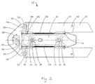
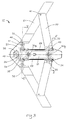
- Figs 2 and 3 show a more detailed view of the wing kit.
- the forward wing 24 section comprises a hardback forward wing pivot 44 , shaped to fit between the said two machined ears 46 on the hardback. Both top and bottom machined ears 46 are shaped to accept the pair of thrust bearings 56 which allows the forward wing 24 to rotate in the horizontal plane located by the forward wing pivot 44 . Attached outboard of the hardback 10 is forward wing 24 .
- the rear wing 22 section similarly comprises a rear wing root casting 30 which attaches to rear wing pivot 48 mounted on carriage 26 attached to driveshafts 28 .
- the rear wing pivot 48 is located to the rear to ensure that said rear wing 22 rotation during extension can proceed freely.
- the rear wing 22 is attached to the root casting in a similar manner to the said forward wing 24 .
- the end plate of the rear wing is machined to accept a rear wing pivot 48 which joins each pair of forward wings 24 and rear wings 22 outboard of the midpoint of forward wing 24 .
- the hardback 10 comprises a casting streamlined at the front end to minimize the increased drag.
- This streamlined structure is hollow and contains power source 38 and motor 40 connected by gear trains 36 to driveshafts 28 mounted on each side of hardback 10 .
- main cross beam 54 supports machined ears 46 which hold thrust bearings 56 and hardback forward wing pivots 44 and forms the main load path to react the forward wing 24 root bending moment.
- This main cross beam 54 also provides the forward support for the driveshafts 28 .
- the hardback casting 10 formed around the munition upper surface and containing internal structure at the hardback lug pockets 18 to attach the guided munition or missile 12 , to the hardback 10 , by means of the hardback lugs 16 , to the carrier aircraft. Aft of the rear hardback lug pockets 18 , the hardback 10 terminates with a tapering streamlined closure which also acts as a rear support for the said driveshafts 28 .
- the hardback 10 is shaped to provide a forward driveshaft support 32 and a rear driveshaft support 34 for the two said driveshafts 28 mounted on each side.
- the driveshafts are driven by gear trains 36 from a centrally mounted power source 38 and a motor 40 to ensure symmetrical operation and deployment of the forward wing 24 and rear wing 22 surfaces.
- the final deployed diamond wing planform is achieved with two wing surfaces linked with a wing tip pivot pin 42 .
- the forward wing 24 forming the leading edge of the planform, rotates on a hardback forward wing pivot 44 between machined ears 46 on the front section of the hardback, the hardback forward wing pivot 44 being supported by roller bearings in each machined ear 46 .
- the rear wing 22 pivots freely about the forward wing 24 attached to said forward wing 24 by said wing tip pivot pin 42 at about 75% of span, and is supported at the inboard end by rear wing root casting 30 attached through a rear wing pivot 48 attached to carriage 26 running on driveshaft 28 .
- one of the major design drives is the reaction of the root bending moment from the wing lift, without a continuous main spar.
- the forward wing 24 is mounted to a forward wing root structure 52 , which pivots on a wide thrust bearing 56 attached to the main cross beam 54 .
- the assembly is streamlined by a hardback cover 50 .
- This combined structure provides a satisfactory load path to limit the induced stresses.
- the forward wing pivot 44 and wing tip pivot pin 42 provide mutual stabilization and torsional stiffness for both wings, 22 and 24 , any wing twist being reacted by bending in the other wing. This design allows a simple, easily produced extrusion without the complexity of one or more internal shear webs.
- Fig 4 and 5 show more details of the wing attachment at both the front (fig 4) and rear (fig 5) attachment stations and the hardback 10 cross section with the internal structure necessary for attachment with the hardback lugs 16a , 16b and the reaction of the swaybrace pads 20 with the swaybraces 420.
- the position of the forward wing 24 attachment points is a compromise between ensuring a compact stowed configuration of the forward wing 24 and said rear wing 22 sections with minimal lateral extension beyond the munition body diameter and minimizing the installed height of the hardback 10 above the guided munition or missile 12 top surface.
- the embodiment shown only extends a minor amount above the original lug position, thereby reducing drag and interference with the carriage aircraft and other stores compared with other art.
- the compactness of the design reduces the undeployed physical envelope, and limits installed drag increments.
- the forward wing 24 moves rapidly outboard as the roots of rear wings 22 are driven aft by the movement of carriage 26 .
- the drag loads are low and assist the motion of the rear wing 22 .
- the geometry slows the rate of deployment of the forward wings 24 .
- the wings 22 , 24 become fully deployed, the increased mechanical advantage of the driveshafts 28 offsets the increase in drag force.
- full deployment is realized with the most favourable geometry.
- This design offers a balanced deployment mechanism that considerably reduces the risk associated with traditional systems.
- the symmetry and deployment scheme of the planform retains the Centre of pressure from the wing lift aft of the Centre of gravity at all times to ensure that the vehicle remains stable during wing extension and freeflight. Wing retraction is achieved by reversing the process.
- the diamond wing design provides a number of important aerodynamic characteristics.
- the wing offers light weight and high torsional stiffness coupled with a high trimmed maximum lift coefficient and benign stall characteristics.
- the combination of swept forward and swept aft wings joined towards the outer edge induces an energetic inward flow along the upper surface of the rear wings 22 which will scour the tip region, re-energize the boundary layer, and delay the typical tip stall. Separation will spread slowly from the root producing a smooth flat topped lift curve with an increase in the linear range of C L (lift coefficient) and a higher C L MAX (maximum lift coefficient).
- the invention can provide a significant increase in cost effectiveness for inventory and developmental weapons by providing a significant increase in range and manouverability by the addition of a simple wing kit in accordance with the invention that utilizes existing standard weapons suspension points and installed munition or missile guidance and control systems.
- Applications of the invention include, but are not limited to, use on inertially aided free fall weapons, rocket boosted, rocket sustained, turbine powered, propeller driven guided missiles or unmanned vehicles both air or surface launched.
- the compact profile of the installed retracted diamond wing kit is compatible with standard stores suspension equipment and space availability with a large number of aircraft for both internal and external carriage.
- the relatively low cost of the system and ease of installation provide a highly cost effective upgrade to a variety of inventory and developmental guided weapons.
- the wing mechanism need not be a discrete assembly attached to a conventional munition, but can be designed into the structure of a new missile.
- the wing need not always be used in the fully extended state, but may be fully or partially extended or retracted as appropriate to control lift and drag to meet various mission profile requirements including launch, cruise, and terminal engagement.
- Multiple wings in accordance with the invention may be used in both vertical and horizontal planes to provide not only lift but side force.
- the system can be manufactured in a fixed extended wing position where prelaunch carriage is not constrained to preclude the wing extended configuration and eliminate the parts required for extension.
- the wing kit may be mounted under the weapons by straps, eliminating the need for lug attachments and swaybrace support.
Landscapes
- Engineering & Computer Science (AREA)
- Mechanical Engineering (AREA)
- Aviation & Aerospace Engineering (AREA)
- Physics & Mathematics (AREA)
- Fluid Mechanics (AREA)
- General Engineering & Computer Science (AREA)
- Aiming, Guidance, Guns With A Light Source, Armor, Camouflage, And Targets (AREA)
Description
- The present invention relates to wings for a guided projectile, or a guided airborne body such as a bomb, dispenser, munition or missile. It particularly relates to extendible wings and the power deployment mechanism thereof whereby for carriage or dense packing considerations the wings are folded but for flight the wings are extended by the action of a power element.
- Proposals have been made to add airfoil surfaces to munitions or missiles to provide control and extended range capability. Prior art proposals include multiple pop out flight surfaces, an extendible pair of wings, or joined wings comprising front and rear spars with flexible coverings to join the spars forming a single aerodynamic surface. Another proposal is joined wings for aircraft that provide flexible and foldable surfaces with a control mechanism. In the above joined wing concepts, the root attachment points are stationary hinge points and strength is achieved through joining the wings and elevating the root of the rear wing providing compression of the upper (rear) wing under load. These prior art proposals have a number of disadvantages, being either fragile, producing insufficient lift for heavy weapons, expensive if they contained control mechanisms, or could not be extended into a flight configuration after launch from an aircraft or ground launch mechanism such as a tube. United States Patent US 3,942,747, (Wolkovick) discusses the advantages of using a joined wing configuration for lightweight aircraft configurations. The extension mechanisms are manual and unpowered and the design is intended to provide torsional stiffness by offsetting the root attachments in the vertical plane as previously discussed. The flexible airfoil surfaces also provide a means for control through cables that will warp the wings to control lift, pitch and bank angle for a manned aircraft. This design requires that the joined wing tips be manually fastened together at the tips after extension from the storage configuration, an unacceptable process after launch from an aircraft or out of a tube. United States Patent US 4,923,143,(Steuer) describes a folding front and rear spar which uses a fabric covering to form a single wing. The power element is attached to a slider which pushes against both spars to effect extension. United States Patent US 4,858,851 describes a spring-deployed telescoping set of fabric covered spars which forms a single lifting surface. In both the preceding patents, the generated wing is fragile, inefficient, and unable to achieve high lift over drag ratios. United States Patent US 5,141,175, (Harris) describes a spring powered extendible scissor wing using downwash control to control pitch and bank angle. The Harris scissor wing has a large structure to accommodate in the folded position. The control element is expensive and unnecessarily redundant to munitions and missiles that already have guidance and control mechanisms.
- United Kingdom Patent GB A 1597098 which is a base for the preamble of claim 1, discloses an arrangement in which each wing or fin consists of two discrete portions which are hinged together at what is the wing tip in the deployed position. In one arrangement two wing portions are arranged in line with the missile axis in the stowed position and are moved to the deployed position after launch by a hydraulic jack or spring which rotates the rear wing portion to its deployed position, pulling the forward wing portion into its deployed position as it does. The leading edge of the rear wing portion nests within a recess in the forward portion so that the two portions form a single wing.
- This document also discloses another arrangement in which fins have corresponding stowed and deployed configurations but are arranged to be deployed before the missile leaves its launch chamber. The in-board ends of the rearward fin portions are coupled to a common carriage which surrounds the missile motor's exhaust pipe and constitutes the nozzle of the motor. Exhaust gases from the missile motor are constrained by a deflector plate in the missile launch chamber and urge the carriage along the pipe, causing the fin portions to emerge through covered cut outs in the walls of the launch chamber to assume a deployed position in which each rearward portion cooperates with a respective forward portion to form respective single fins. Magnetic rings lock the carriage (and thus the fins) in position when the fins are fully extended.
- In accordance with the invention, an extendable wing assembly for a guided munition comprises:
- a housing; a rear wing (22); a forward wing (24) pivotably coupled to the rear wing (22) at an outer end thereof, an inner end of one (24) of the forward and rear wings (22, 24) being pivotably coupled to the housing; a carriage assembly (26) arranged to be movable along an axis of the housing, an inner end of the other wing (22) being pivotably coupled to the carriage assembly (26), movement of the carriage assembly (26) along the axis causing the wings (22, 24) to move between a first position in which the wings (22, 24) are stowed and a second position in which the wings are deployed; characterised in that the rear wing (22) lies on top of the forward wing (24) in the first position and in that the wings (22,24) are arranged to move pivotally forward between the first position and the second position in response to movement of the carriage assembly (26) along said axis.
-
- An advantage of the invention is that it derives lift from a diamond planform where the rear wing acts in conjunction with the power source to extend, preferably after launch, an aerodynamically balanced, high lift to drag ratio front and rear wing joined close to the wingtips to form a diamond configuration without an integrated guidance and control system. This system provides a compact low cost range extension kit compatible with a large inventory of guided munitions and missiles. Advantageously, the folded wings and deployment mechanism are contained in a small cross sectional and longitudinal area providing minimum interference with host aircraft structure and low aerodynamic drag for carriage on a large variety of aircraft and weapon stations. Extension of the wing maybe accomplished by powering the rear wing root to the rear causing the joined wings to rotate to the extended position. The high efficiency and strength of the deployed wings can provide long range and weapon manouverability. The simplicity of the kit using existing and standard suspension points provide for low cost installation and cost of ownership.
- Embodiments of the invention will now be described by way of non-limiting example only, with reference to the drawings, in which
- Figure 1 (a), (b) and (c) show successive stages in the deployment of an extendible wing kit in accordance with the invention assembled to a weapon;
- Figure 2 shows a plan view of the wing kit of Figure 1 in the folded state;
- Figure 3 shows a plan view of the wing kit of Figure 1 in its deployed state;
- Figure 4 shows a sectional view of Figure 3 along IV-IV;
- Figure 5 shows a sectional view of Figure 4 along V-V.
-
- Referring now to figure 1, a
munition 12 has a wing kit secured to an upper surface thereof. In the folded position (Fig 1a), therear wing 22 lies on top of theforward wing 24 and stows closely to the side of ahardback 10 at about the same vertical level as the upper surface of themunition 12 and with amovable carriage 26 supporting therear wing 22 at the most forward position of travel. To deploy the joined wings, 22 and 24, thecarriages 26 are moved aft on and by the action of a pair ofdriveshafts 28. The rearward movement of thecarriages 26, each attached to a rearwing root casting 30, and the relative geometry of the joined wing surfaces, forces theforward wing 24 to pivot out, thereby forming a triangular (diamond) planform, (Fig 1b). The deployment is complete when therear wing 22 passes 90 degrees of rotation. With less than 90 degrees of rotation the wings, 22 and 24, rely upon the saiddriveshafts 28 to maintain deployment. Above 90 degrees the planform locks into position (Fig 1c) under the action of the overall drag force produced by the movement of the munition through the air, and requires a positive action to restow the wings. - In the fully folded position (Fig 1a) the wing panels lie on either side of the
hardback 10 with therear wing 22 laying on top of theforward wing 24. Thestreamlined hardback 10 bolts to the guided missile ormunition 12 by way of standardmunition lug wells 14, these generally being but not limited to, either 14 inch (355.6mm) or 30 inch (762mm) spacing depending upon the weight class of themunition 12. Thehardback 10 includes an additional set ofhardback lugs 16 andhardback lug pockets 18, mounted above the existingmunition lug wells 14 for attachment to themunition 12 and the parent aircraft. The existing munition lug positions (14) as fitted withnew hardback lugs adjacent swaybrace pads 20, can be seen from the top of thehardback 10. Fourswaybrace pads 20 are machined on thehardback 10 adjacent to thehardback lugs 16 to react to the release unit swaybrace loads. Thehardback 10 design is such that the additional height of the final lug position above themunition 12 upper surface is as small as possible. - Figure 1a represents the carriage configuration where the
munition 12 and wing kit would be attached by thenew hardback lugs munition 12 from the aircraft, the folded configuration is maintained for a period of time calculated to ensure safe clearance of the munition from the vicinity of the launch platform. After this delay measured by a simple onboard timer (not shown) power is applied to the deployment mechanism and the saidcarriages 26 starts to move aft on thedriveshafts 28. This state is shown in Fig 1b. Because of the relative spans of the two wing components, the geometry forces theforward wing 24 to rotate outwards and therear wing 22 follows as shown. Fig 1c shows the deployment complete with thecarriage 26 moved to the furthest aft position, therear wing 22 having rotated by more than 90 degrees to ensure positive location in a diamond configuration. - The design is such that the aerodynamic Centre is well aft in the folded configuration to provide a stable carriage and launch vehicle. As the deployment progresses, the aerodynamic Centre moves forward until the
rear wing 22 reaches approximately 90 degrees of rotation (Fig 1b). As the rotation continues the sweep angle of theforward wing 24 starts to reduce and the aerodynamic Centre begins to move aft. The geometry is designed to provide the optimum static margin of the combined guided munition ormissile 12 and fully deployed wing kit without entering any unstable configurations during the deployment process, thus remaining within the control authority of the munition guidance system. - Figs 2 and 3 show a more detailed view of the wing kit. The
forward wing 24 section comprises a hardbackforward wing pivot 44, shaped to fit between the said two machinedears 46 on the hardback. Both top and bottom machinedears 46 are shaped to accept the pair ofthrust bearings 56 which allows theforward wing 24 to rotate in the horizontal plane located by theforward wing pivot 44. Attached outboard of thehardback 10 is forwardwing 24. - The
rear wing 22 section similarly comprises a rear wing root casting 30 which attaches torear wing pivot 48 mounted oncarriage 26 attached to driveshafts 28. Therear wing pivot 48 is located to the rear to ensure that saidrear wing 22 rotation during extension can proceed freely. Therear wing 22 is attached to the root casting in a similar manner to the saidforward wing 24. The end plate of the rear wing is machined to accept arear wing pivot 48 which joins each pair offorward wings 24 andrear wings 22 outboard of the midpoint offorward wing 24. - The
hardback 10 comprises a casting streamlined at the front end to minimize the increased drag. This streamlined structure is hollow and containspower source 38 andmotor 40 connected bygear trains 36 todriveshafts 28 mounted on each side ofhardback 10. Behind the hardback frontstreamlined structure 50,main cross beam 54 supports machinedears 46 which holdthrust bearings 56 and hardback forward wing pivots 44 and forms the main load path to react theforward wing 24 root bending moment. Thismain cross beam 54 also provides the forward support for thedriveshafts 28. Behind, and attached to, themain cross beam 54 is the hardback casting 10 formed around the munition upper surface and containing internal structure at the hardback lug pockets 18 to attach the guided munition ormissile 12, to thehardback 10, by means of the hardback lugs 16, to the carrier aircraft. Aft of the rear hardback lug pockets 18, thehardback 10 terminates with a tapering streamlined closure which also acts as a rear support for the saiddriveshafts 28. - The
hardback 10 is shaped to provide aforward driveshaft support 32 and arear driveshaft support 34 for the two saiddriveshafts 28 mounted on each side. The driveshafts are driven bygear trains 36 from a centrally mountedpower source 38 and amotor 40 to ensure symmetrical operation and deployment of theforward wing 24 andrear wing 22 surfaces. - The final deployed diamond wing planform is achieved with two wing surfaces linked with a wing
tip pivot pin 42. Theforward wing 24, forming the leading edge of the planform, rotates on a hardbackforward wing pivot 44 betweenmachined ears 46 on the front section of the hardback, the hardbackforward wing pivot 44 being supported by roller bearings in eachmachined ear 46. Therear wing 22 pivots freely about theforward wing 24 attached to saidforward wing 24 by said wingtip pivot pin 42 at about 75% of span, and is supported at the inboard end by rear wing root casting 30 attached through arear wing pivot 48 attached tocarriage 26 running ondriveshaft 28. - As with most deployable wing systems, one of the major design drives is the reaction of the root bending moment from the wing lift, without a continuous main spar. With the present design, the
forward wing 24 is mounted to a forwardwing root structure 52, which pivots on a wide thrust bearing 56 attached to themain cross beam 54. The assembly is streamlined by ahardback cover 50. This combined structure provides a satisfactory load path to limit the induced stresses. Theforward wing pivot 44 and wingtip pivot pin 42 provide mutual stabilization and torsional stiffness for both wings, 22 and 24, any wing twist being reacted by bending in the other wing. This design allows a simple, easily produced extrusion without the complexity of one or more internal shear webs. - Fig 4 and 5 show more details of the wing attachment at both the front (fig 4) and rear (fig 5) attachment stations and the hardback 10 cross section with the internal structure necessary for attachment with the hardback lugs 16a, 16b and the reaction of the
swaybrace pads 20 with theswaybraces 420. - The position of the
forward wing 24 attachment points is a compromise between ensuring a compact stowed configuration of theforward wing 24 and saidrear wing 22 sections with minimal lateral extension beyond the munition body diameter and minimizing the installed height of thehardback 10 above the guided munition ormissile 12 top surface. The embodiment shown only extends a minor amount above the original lug position, thereby reducing drag and interference with the carriage aircraft and other stores compared with other art. - The compactness of the design reduces the undeployed physical envelope, and limits installed drag increments. During the initial stages of deployment the
forward wing 24 moves rapidly outboard as the roots ofrear wings 22 are driven aft by the movement ofcarriage 26. At this point, the drag loads are low and assist the motion of therear wing 22. Asrear wings 22 are driven further, the geometry slows the rate of deployment of theforward wings 24. As thewings driveshafts 28 offsets the increase in drag force. Thus, full deployment is realized with the most favourable geometry. This design offers a balanced deployment mechanism that considerably reduces the risk associated with traditional systems. The symmetry and deployment scheme of the planform retains the Centre of pressure from the wing lift aft of the Centre of gravity at all times to ensure that the vehicle remains stable during wing extension and freeflight. Wing retraction is achieved by reversing the process. - The diamond wing design provides a number of important aerodynamic characteristics. The wing offers light weight and high torsional stiffness coupled with a high trimmed maximum lift coefficient and benign stall characteristics. The combination of swept forward and swept aft wings joined towards the outer edge induces an energetic inward flow along the upper surface of the
rear wings 22 which will scour the tip region, re-energize the boundary layer, and delay the typical tip stall. Separation will spread slowly from the root producing a smooth flat topped lift curve with an increase in the linear range of CL (lift coefficient) and a higher CL MAX (maximum lift coefficient). - Preferably each airfoil of the wing is designed to operate in the curved flowfield generated by lift on the adjacent airfoil. Of necessity this implies differences between said
forward wing 24 and saidrear wing 22 sections. - Accordingly it can be seen that the invention can provide a significant increase in cost effectiveness for inventory and developmental weapons by providing a significant increase in range and manouverability by the addition of a simple wing kit in accordance with the invention that utilizes existing standard weapons suspension points and installed munition or missile guidance and control systems. Applications of the invention include, but are not limited to, use on inertially aided free fall weapons, rocket boosted, rocket sustained, turbine powered, propeller driven guided missiles or unmanned vehicles both air or surface launched. The compact profile of the installed retracted diamond wing kit is compatible with standard stores suspension equipment and space availability with a large number of aircraft for both internal and external carriage. The relatively low cost of the system and ease of installation provide a highly cost effective upgrade to a variety of inventory and developmental guided weapons.
- Many other modifications and variations are possible within the scope of the invention. For example, the wing mechanism need not be a discrete assembly attached to a conventional munition, but can be designed into the structure of a new missile. The wing need not always be used in the fully extended state, but may be fully or partially extended or retracted as appropriate to control lift and drag to meet various mission profile requirements including launch, cruise, and terminal engagement. Multiple wings in accordance with the invention, may be used in both vertical and horizontal planes to provide not only lift but side force. The system can be manufactured in a fixed extended wing position where prelaunch carriage is not constrained to preclude the wing extended configuration and eliminate the parts required for extension. The wing kit may be mounted under the weapons by straps, eliminating the need for lug attachments and swaybrace support. The lugs can be replaced by railguides for boosted rail or tube launch. Extension and retraction of the wings may be controlled via a remote communications link as well as or instead of in response to a timer.
Claims (14)
- An extendable wing assembly (10) for a guided munition (12) comprising:characterised in that the rear wing (22) lies on top of the forward wing (24) in the first position and in that the wings (22,24) are arranged to move pivotally forward between the first position and the second position in response to movement of the carriage assembly (26) along said axis.a housing;a rear wing (22);a forward wing (24) pivotably coupled to the rear wing (22) at an outer end thereof, an inner end of one (24) of the forward and rear wings (22, 24) being pivotably coupled to the housing;a carriage assembly (26) arranged to be movable along an axis of the housing, an inner end of the other wing (22) being pivotably coupled to the carriage assembly (26), movement of the carriage assembly (26) along the axis causing the wings (22, 24) to move between a first position in which the wings (22, 24) are stowed and a second position in which the wings are deployed;
- An extendable wing assembly as claimed in claim 1, characterised by a motor (40) disposed within the housing, and coupling means (28, 36) arranged between the motor (40) and the carriage assembly (26) such that operation of the motor (40) causes movement of the carriage assembly (26) along the axis.
- An extendable wing assembly as claimed in claim 2 characterised in that coupling means (26, 36) comprises a driveshaft (28) arranged to be driven by the motor (40)such that rotation of the motor (40) causes translation of the carriage assembly (26).
- An extendable wing assembly as claimed in claim 3, characterised in that the coupling means (28, 36) further comprises a gear train (36) coupling the motor (40) to the driveshaft (28) .
- An extendable wing assembly as claimed in any preceding claim, characterised in that the inner end of the rear wing (22) is pivotally coupled to the carriage assembly (26) .
- An extendable wing assembly as claimed in claim 5, characterised in that the driveshaft (28) maintains deployment of the wings (22, 24) when the rotation of the wings (22, 24) is less than 90 degrees, and in that deployment is complete when the rear wing (22) passes 90 degrees of rotation.
- An extendable wing assembly as claimed in claim 6, characterised in that the wings (22, 24) form a triangular planform which is locked into position above 90 degrees of rotation.
- An extendable wing assembly as claimed in any preceding claim, characterised by two forward and rear wings (22, 24) and two carriage assemblies (26), each carriage assembly (26) being associated with a forward and a rear wing (22, 24) and located on one side of the housing.
- An extendable wing assembly as claimed in any preceding claim comprising by a discrete unit arranged to be attached to a guided munition (12).
- An extendable wing assembly as claimed in claim 9, characterised in that housing comprises a hardback (10) arranged to be secured to the munition (12) by lug wells (14) thereof.
- An extendable wing assembly as claimed in claim 9 or 10, characterised in that means to accept mounting lugs (16a, 16b) for mounting the munition (12) on weapon suspension equipment.
- An extendable wing assembly as claimed in claim 9, characterised in that the housing is arranged to be secured to the munition (12) by straps.
- An extendable wing assembly as claimed in any preceding claim, characterised by means to deploy the wings (22, 24) after launch.
- An extendable wing assembly as claimed in any preceding claim, characterised by means to adjust the configuration of the wings (22, 24) during flight.
Priority Applications (2)
| Application Number | Priority Date | Filing Date | Title |
|---|---|---|---|
| DE69631286T DE69631286T2 (en) | 1996-06-07 | 1996-06-07 | Foldable wing element |
| EP96304319A EP0811822B1 (en) | 1996-06-07 | 1996-06-07 | Extendable wing assembly |
Applications Claiming Priority (1)
| Application Number | Priority Date | Filing Date | Title |
|---|---|---|---|
| EP96304319A EP0811822B1 (en) | 1996-06-07 | 1996-06-07 | Extendable wing assembly |
Publications (2)
| Publication Number | Publication Date |
|---|---|
| EP0811822A1 EP0811822A1 (en) | 1997-12-10 |
| EP0811822B1 true EP0811822B1 (en) | 2004-01-07 |
Family
ID=8224971
Family Applications (1)
| Application Number | Title | Priority Date | Filing Date |
|---|---|---|---|
| EP96304319A Expired - Lifetime EP0811822B1 (en) | 1996-06-07 | 1996-06-07 | Extendable wing assembly |
Country Status (2)
| Country | Link |
|---|---|
| EP (1) | EP0811822B1 (en) |
| DE (1) | DE69631286T2 (en) |
Families Citing this family (16)
| Publication number | Priority date | Publication date | Assignee | Title |
|---|---|---|---|---|
| SE519757C2 (en) | 2000-08-15 | 2003-04-08 | Bofors Defence Ab | Controllable artillery projectile with extremely long range |
| AU2003304082A1 (en) * | 2002-08-30 | 2004-11-26 | Raytheon Company | Winged vehicle with deployable wings mounted to a translating pivot mechanism |
| RU2289779C1 (en) * | 2005-05-23 | 2006-12-20 | Государственное унитарное предприятие "Конструкторское бюро приборостроения" | Aerodynamic control surface of guided missile |
| CN103661919A (en) * | 2013-12-23 | 2014-03-26 | 北京理工大学 | Wing folding mechanism based on flex-wing aircraft |
| DE102015014502A1 (en) * | 2015-11-10 | 2017-05-11 | Mbda Deutschland Gmbh | Auxiliary airfoil device |
| CN109489499B (en) * | 2018-12-26 | 2024-02-06 | 湖南省军合科技有限公司 | 3D prints foldable wing and patrols flying saucer |
| CN112265631B (en) * | 2020-10-16 | 2022-07-12 | 中国空气动力研究与发展中心 | Box-type folding wing unmanned aerial vehicle layout capable of realizing modular assembly with variable aspect ratio |
| CN112896487B (en) * | 2021-01-28 | 2022-10-21 | 西安电子科技大学 | Unmanned aerial vehicle synchronous unfolding and folding system, method and application |
| DE102021001038C5 (en) * | 2021-02-26 | 2025-03-20 | Diehl Defence Gmbh & Co. Kg | Aircraft with wing folding mechanism |
| CN113772077B (en) * | 2021-08-27 | 2023-03-31 | 哈尔滨工业大学 | Unmanned aerial vehicle wing unblock and horizontal rotation expandes device |
| CN114248906B (en) * | 2021-11-14 | 2022-06-21 | 北京工业大学 | Aircraft wing folding device |
| CN116674748B (en) * | 2022-04-12 | 2026-04-14 | 中国航空工业集团公司西安飞机设计研究所 | Aircraft air drop packing box |
| CN115056980B (en) * | 2022-06-20 | 2024-12-20 | 哈尔滨工业大学(深圳) | Variable-sweep wing assembly of water-air cross-medium flapping-wing aircraft and flapping-wing aircraft |
| CN115783332B (en) * | 2022-12-26 | 2025-05-16 | 北华航天工业学院 | A tandem wing linkage folding and unfolding mechanism for unmanned aerial vehicle |
| DE102023001553B3 (en) * | 2023-04-19 | 2024-09-26 | Mbda Deutschland Gmbh | UNPROPELLED AUXILIARY DEVICE AND MISSILE SYSTEM |
| WO2025147217A1 (en) * | 2024-01-03 | 2025-07-10 | Durmus Fatih | Roll wing system |
Family Cites Families (7)
| Publication number | Priority date | Publication date | Assignee | Title |
|---|---|---|---|---|
| US1998148A (en) * | 1934-04-18 | 1935-04-16 | Vieriu Daniel | Auto-aeroplane |
| FR1563898A (en) * | 1968-02-13 | 1969-04-18 | ||
| GB1597098A (en) * | 1971-06-23 | 1981-09-03 | British Aerospace | Missiles |
| US4586681A (en) * | 1983-06-27 | 1986-05-06 | General Dynamics Pomona Division | Supersonic erectable fabric wings |
| FR2600618A1 (en) * | 1986-06-27 | 1987-12-31 | Thomson Brandt Armements | WING WITH MULTIPLE DEPLOYMENT AND ITS APPLICATION TO A FLYING DEVICE |
| DE3838738A1 (en) * | 1988-11-15 | 1990-05-23 | Diehl Gmbh & Co | PROJECTILE WITH FOLD-OUT WINGS |
| US5141175A (en) * | 1991-03-22 | 1992-08-25 | Harris Gordon L | Air launched munition range extension system and method |
-
1996
- 1996-06-07 EP EP96304319A patent/EP0811822B1/en not_active Expired - Lifetime
- 1996-06-07 DE DE69631286T patent/DE69631286T2/en not_active Expired - Lifetime
Non-Patent Citations (2)
| Title |
|---|
| ONIONS C.T.: "The Shorter Oxford Dictionary", 1991, CLARENDON PRESS, OXFORD * |
| PARKER S.: "Mcgraw-Hill Concise Encyclopedia of Science and Technology, pages 36, 37, 48, 49, 2024, 2025", 1989, MCGRAW-HILL COMPANY, NEW YORK * |
Also Published As
| Publication number | Publication date |
|---|---|
| EP0811822A1 (en) | 1997-12-10 |
| DE69631286T2 (en) | 2004-06-03 |
| DE69631286D1 (en) | 2004-02-12 |
Similar Documents
| Publication | Publication Date | Title |
|---|---|---|
| US5615846A (en) | Extendable wing for guided missles and munitions | |
| EP0811822A1 (en) | Extendable wing assembly | |
| US7841559B1 (en) | Aerial vehicle with variable aspect ratio deployable wings | |
| EP0013096B1 (en) | Deployable wing mechanism | |
| US4336914A (en) | Deployable wing mechanism | |
| US7185847B1 (en) | Winged vehicle with variable-sweep cantilevered wing mounted on a translating wing-support body | |
| US5671899A (en) | Airborne vehicle with wing extension and roll control | |
| US5899410A (en) | Aerodynamic body having coplanar joined wings | |
| US9688397B2 (en) | Aircraft with a plurality of engines driving a common driveshaft | |
| US6974105B2 (en) | High performance VTOL convertiplanes | |
| US5154370A (en) | High lift/low drag wing and missile airframe | |
| WO2008010226A1 (en) | Air vehicle and deployable wing arrangement therefor | |
| CN113165741A (en) | Aircraft and modular propulsion unit | |
| EP1222380B1 (en) | Swing pivot thrust reverser | |
| US2925233A (en) | Aircraft wing fold system | |
| US6616092B1 (en) | Reusable flyback rocket booster and method for recovering same | |
| CA2519871C (en) | Winged spacecraft | |
| US10429159B2 (en) | Deployable airfoil airborne body and method of simultaneous translation and rotation to deploy | |
| US6598827B2 (en) | Telescopic vertical take-off aircraft | |
| US4090684A (en) | Stowable airfoil structure | |
| US5201832A (en) | Integrated aerospike engine and aerobrake for a spacecraft | |
| US7717370B2 (en) | L-tail (featuring parabrakes) | |
| AU735110B2 (en) | Extendable wing assembly | |
| US5320304A (en) | Integrated aerodynamic fin and stowable TVC vane system | |
| CN115056966A (en) | Z-shaped folding wing unmanned aerial vehicle wing folding framework and working method thereof |
Legal Events
| Date | Code | Title | Description |
|---|---|---|---|
| PUAI | Public reference made under article 153(3) epc to a published international application that has entered the european phase |
Free format text: ORIGINAL CODE: 0009012 |
|
| AK | Designated contracting states |
Kind code of ref document: A1 Designated state(s): DE FR GB IT |
|
| 17P | Request for examination filed |
Effective date: 19980608 |
|
| 17Q | First examination report despatched |
Effective date: 19990127 |
|
| RAP1 | Party data changed (applicant data changed or rights of an application transferred) |
Owner name: ALENIA MARCONI SYSTEMS INCORPORATED |
|
| GRAP | Despatch of communication of intention to grant a patent |
Free format text: ORIGINAL CODE: EPIDOSNIGR1 |
|
| GRAS | Grant fee paid |
Free format text: ORIGINAL CODE: EPIDOSNIGR3 |
|
| GRAA | (expected) grant |
Free format text: ORIGINAL CODE: 0009210 |
|
| AK | Designated contracting states |
Kind code of ref document: B1 Designated state(s): DE FR GB IT |
|
| REG | Reference to a national code |
Ref country code: GB Ref legal event code: FG4D |
|
| REF | Corresponds to: |
Ref document number: 69631286 Country of ref document: DE Date of ref document: 20040212 Kind code of ref document: P |
|
| ET | Fr: translation filed | ||
| PLBE | No opposition filed within time limit |
Free format text: ORIGINAL CODE: 0009261 |
|
| STAA | Information on the status of an ep patent application or granted ep patent |
Free format text: STATUS: NO OPPOSITION FILED WITHIN TIME LIMIT |
|
| 26N | No opposition filed |
Effective date: 20041008 |
|
| PGFP | Annual fee paid to national office [announced via postgrant information from national office to epo] |
Ref country code: GB Payment date: 20140618 Year of fee payment: 19 |
|
| PGFP | Annual fee paid to national office [announced via postgrant information from national office to epo] |
Ref country code: DE Payment date: 20140619 Year of fee payment: 19 |
|
| PGFP | Annual fee paid to national office [announced via postgrant information from national office to epo] |
Ref country code: FR Payment date: 20140619 Year of fee payment: 19 |
|
| PGFP | Annual fee paid to national office [announced via postgrant information from national office to epo] |
Ref country code: IT Payment date: 20140630 Year of fee payment: 19 |
|
| REG | Reference to a national code |
Ref country code: DE Ref legal event code: R119 Ref document number: 69631286 Country of ref document: DE |
|
| PG25 | Lapsed in a contracting state [announced via postgrant information from national office to epo] |
Ref country code: IT Free format text: LAPSE BECAUSE OF NON-PAYMENT OF DUE FEES Effective date: 20150607 |
|
| GBPC | Gb: european patent ceased through non-payment of renewal fee |
Effective date: 20150607 |
|
| REG | Reference to a national code |
Ref country code: FR Ref legal event code: ST Effective date: 20160229 |
|
| PG25 | Lapsed in a contracting state [announced via postgrant information from national office to epo] |
Ref country code: DE Free format text: LAPSE BECAUSE OF NON-PAYMENT OF DUE FEES Effective date: 20160101 Ref country code: GB Free format text: LAPSE BECAUSE OF NON-PAYMENT OF DUE FEES Effective date: 20150607 |
|
| PG25 | Lapsed in a contracting state [announced via postgrant information from national office to epo] |
Ref country code: FR Free format text: LAPSE BECAUSE OF NON-PAYMENT OF DUE FEES Effective date: 20150630 |