EP0811152B1 - Fuel vapor leak detection system - Google Patents
Fuel vapor leak detection system Download PDFInfo
- Publication number
- EP0811152B1 EP0811152B1 EP96901206A EP96901206A EP0811152B1 EP 0811152 B1 EP0811152 B1 EP 0811152B1 EP 96901206 A EP96901206 A EP 96901206A EP 96901206 A EP96901206 A EP 96901206A EP 0811152 B1 EP0811152 B1 EP 0811152B1
- Authority
- EP
- European Patent Office
- Prior art keywords
- leak detection
- detection system
- fuel vapor
- flow
- flow sensor
- Prior art date
- Legal status (The legal status is an assumption and is not a legal conclusion. Google has not performed a legal analysis and makes no representation as to the accuracy of the status listed.)
- Expired - Lifetime
Links
Images
Classifications
-
- G—PHYSICS
- G01—MEASURING; TESTING
- G01M—TESTING STATIC OR DYNAMIC BALANCE OF MACHINES OR STRUCTURES; TESTING OF STRUCTURES OR APPARATUS, NOT OTHERWISE PROVIDED FOR
- G01M3/00—Investigating fluid-tightness of structures
- G01M3/02—Investigating fluid-tightness of structures by using fluid or vacuum
- G01M3/26—Investigating fluid-tightness of structures by using fluid or vacuum by measuring rate of loss or gain of fluid, e.g. by pressure-responsive devices, by flow detectors
- G01M3/32—Investigating fluid-tightness of structures by using fluid or vacuum by measuring rate of loss or gain of fluid, e.g. by pressure-responsive devices, by flow detectors for containers, e.g. radiators
-
- F—MECHANICAL ENGINEERING; LIGHTING; HEATING; WEAPONS; BLASTING
- F02—COMBUSTION ENGINES; HOT-GAS OR COMBUSTION-PRODUCT ENGINE PLANTS
- F02M—SUPPLYING COMBUSTION ENGINES IN GENERAL WITH COMBUSTIBLE MIXTURES OR CONSTITUENTS THEREOF
- F02M25/00—Engine-pertinent apparatus for adding non-fuel substances or small quantities of secondary fuel to combustion-air, main fuel or fuel-air mixture
- F02M25/08—Engine-pertinent apparatus for adding non-fuel substances or small quantities of secondary fuel to combustion-air, main fuel or fuel-air mixture adding fuel vapours drawn from engine fuel reservoir
- F02M25/0809—Judging failure of purge control system
- F02M25/0818—Judging failure of purge control system having means for pressurising the evaporative emission space
Definitions
- This invention relates to an on-board system for detecting fuel vapor leakage from an evaporative emission control system of an automotive vehicle.
- the referenced patent application discloses a leak detection system that employs a differential flow sensing principle for detecting fuel vapor leakage from the evaporative emission system of an automotive vehicle during a leakage test that involves closing the canister purge solenoid (CPS) valve and then positively pressurizing that portion of the evaporative emission system that is upstream of the CPS valve relative to the engine.
- CPS canister purge solenoid
- a leak detection system embodying principles of the present invention possesses potential for improved accuracy and for avoiding false readings that might otherwise arise on account of such variables. More specifically, the inventive leak detection system is capable of canceling out effects of three external variables by comparing the leakage flow with a known calibrated reference leakage.
- the inventive leak detection system also eliminates the need for a relatively expensive pressure transducer used in prior non-differential flow sensing systems to detect pressure decay. It also does not require a canister vent valve used in such prior systems.
- Another aspect of the invention relates to the physical integration of certain components of the leak detection system with a fuel vapor collection canister.
- This aspect provides greater spatial economy (i.e. more compactness) so that when the integrated canister/system is installed in an automotive vehicle, a smaller amount of space is taken up. This savings in space is especially important to many automobile manufacturers, who must build vehicles that comply with both applicable evaporative emission laws and regulations and applicable fuel economy laws and regulations.
- the integration possesses the further advantage of requiring fewer connections of components in the automotive assembly plant, and this affords the opportunity for installation cost savings while at the same time an opportunity for increased reliability of the installation.
- Still another advantage of the invention is that a fuel vapor leak detection test can be performed either when the engine is running or not running.
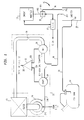
- Fig. 1 is a schematic diagram of a fuel vapor leak detection system embodying principles of the invention.
- Fig. 1 shows an exemplary application of the inventive principles to an automotive vehicle that is powered by an internal combustion engine 10 that is controlled by an electronic engine control 12.
- the vehicle comprises a fuel tank 14 for storing a volatile fuel such as gasoline that is vaporized and combusted in the engine's combustion chamber space.
- the associated evaporative emission control system is designated generally by the reference numeral 16 and comprises: the usual canister purge solenoid (CPS) valve 18 having inlet and outlet ports 18i and 18o respectively; and a vapor collection canister (sometimes called a charcoal canister) 20 having a tank port 20t, a vent port 20v, and purge port 20p.
- CPS canister purge solenoid
- the leak detection system embodying principles of the invention is shown generally at 22 and comprises a pressure source 24, in the form of a device (preferably electrically operated, but alternatively operable by a mechanical input) that, when operated during a test, is capable of pressurizing the evaporative emission space under test, and that, when not being operated, provides venting of the canister vent port to atmosphere.
- a pressure source 24 in the form of a device (preferably electrically operated, but alternatively operable by a mechanical input) that, when operated during a test, is capable of pressurizing the evaporative emission space under test, and that, when not being operated, provides venting of the canister vent port to atmosphere.
- a device 24 is an electric motor driven impeller pump having an inlet 24i and an outlet 24o.
- Leak detection system 22 further comprises a series flow path comprising a first flow sensor 26, a second flow sensor 28, and a calibrated orifice 30 in that order.
- An exemplary device that can be used for each flow sensor is a thermistor, with the two thermistors being connected in electric circuitry that is connected to respective inputs 32a, 32b of differential amplifier 32.
- Amplifier 32 functions to take the difference between the two flows through the respective flow meters and provide at its output 32c, an output signal that is indicative of the flow differential.
- This output signal is delivered to engine control 12, which is a conventional processor programmed to conduct a leak detection test, in addition to controlling other engine functions, including possibly other types of diagnostic tests.
- Canister tank port 20t is coupled with headspace of tank 14 via a conduit 34; purge port 20p is coupled with inlet port 18i of CPS valve 18 via a conduit 36; and vent port 20v is coupled with leak detection system 22 via a conduit 38 that forms a branch circuit that tees into the aforementioned series flow path at a location between the two flow sensors.
- Outlet port 18o of CPS valve 18 is coupled to the intake manifold vacuum that is produced by engine 10 when running.
- CPS valve 18 is operated by engine control 12 to periodically purge the vapor stored in canister 20 to the engine.
- the exact scheduling of such purging is controlled by the vehicle manufacturer's requirements.
- CPS valve 18 When a leak detection test is to be conducted on the evaporative emission control system, CPS valve 18 is operated closed by control 12, and pressure source 24 is operated to beginning drawing outside air through a filter 40 and begin pressurizing that portion of the evaporative emission space comprising tank 14, conduit 34, canister 20, conduit 38, and conduit 36 up to the closed CPS valve. Naturally the vehicle tank filler cap must be in place to close the tank filler tube.
- the series flow path formed by the two sensors 26, 28 and calibrated orifice 30 conducts all or a portion of the flow from pressure source 24 back to atmosphere through filter 40.
- the broken line that bounds leak detection system 22 in Fig. 1 is intended to show that the various components within its confines can form an assembly that directly mounts on the top of canister 20.
- Such a physical integration of components provides more compactness for a canister/leak detection system and requires fewer connections of components in an automotive assembly plant, affording the opportunity for installation cost savings while at the same time an opportunity for increased installation reliability.
Landscapes
- Engineering & Computer Science (AREA)
- Chemical & Material Sciences (AREA)
- Combustion & Propulsion (AREA)
- Mechanical Engineering (AREA)
- General Engineering & Computer Science (AREA)
- Physics & Mathematics (AREA)
- General Physics & Mathematics (AREA)
- Supplying Secondary Fuel Or The Like To Fuel, Air Or Fuel-Air Mixtures (AREA)
- Examining Or Testing Airtightness (AREA)
Description
Claims (9)
- A fuel vapor leak detection system (22) for use in en engine-powered automotive vehicle having an evaporative emission control system (16) including a fuel vapor collection canister (20) with a canister purge valve (18), a fuel tank (14) for storing volatile fuel that is combusted in a combustion chamber space of an engine (10) and being operatively associated with the fuel vapor collection canister (20) that collects volatized fuel from the tank (14), said canister purge valve (18) being periodically operated to purge collected vapor from the canister (20) to the engine (10), said leak detection system (22) being operatively associated with the evaporative emission control system (16) for detecting leakage from that portion of the evaporative emission control system (16) which is upstream of an inlet of the canister purge valve (18) relative to the engine (10), and comprising pressurizing means (24) having an inlet (24i) at which a source of gaseous medium is available to be pressurized by said pressurizing means (24) and an outlet (24o) at which positively pressurized medium is made available for delivery to said portion of the evaporative emission control system;
characterized by a series flow path from said outlet ( 240) of said pressurizing means (24) back to said source of gaseous medium, said series flow path comprising a first flow sensor (26) for sensing the entire flow from said outlet (24o) of said pressurizing means (24), a second flow sensor (28) for sensing flow through a portion of said series flow path that is downstream of said first flow sensor (26) and a calibrated orifice means (30) also disposed in said portion of said series flow path that is downstream of said second flow sensor (28);a branch flow path (38) that branches to said portion of said evaporative emission control system (16) from said series flow path at a location in said series flow path that is between said first flow sensor (26) and said second flow sensor (28);and means (32) for sensing differential between flow sensed by said first flow sensor (26) and flow sensed by said second flow sensor (28). - A fuel vapor leak detection system (22) as claimed in Claim 1, in which said pressurizing means comprises an electrically operated impeller pump (24).
- A fuel vapor leak detection system as claimed in Claim 2, in which said electrically operated impeller pump (24) is physically mounted on said canister (20).
- A fuel vapor leak detection system as claimed in Claim 2 or Claim 3, in which said electrically operated impeller pump, when not being operated, serves to provide a vent from said evaporative emission control system (16) to said source of gaseous medium.
- A fuel vapor leak detection system as claimed in Claim 4, in which said electrically operated impeller pump (24), when not being operated, serves to provide a vent from said first flow sensor (26) to said source of gaseous medium.
- A fuel vapor leak detection system as claimed in Claims 2, 3, 4 or 5, including a filter (40) through which said electrically operated impeller pump (24), when not being operated, serves to provide a vent from said evaporative emission control system (16) by way of said first flow sensor (26) to said source of gaseous medium.
- A fuel vapor leak detection system as claimed in any preceding Claim, in which said source of gaseous medium is atmospheric air.
- A fuel vapor leak detection system as claimed in Claim 1, including a filter (40) through which said pressurizing means (24), when not being operated, serves to provide a vent from said evaporative emission control system (16) to said source of gaseous medium.
- A fuel vapor leak detection system as claimed in any preceding Claim, in which said means (32) for sensing differential between flow sensed by said first flow sensor (26) and flow sensed by said second flow sensor (28) comprises a differential amplifier.
Applications Claiming Priority (3)
| Application Number | Priority Date | Filing Date | Title |
|---|---|---|---|
| US08/393,952 US5483942A (en) | 1995-02-24 | 1995-02-24 | Fuel vapor leak detection system |
| US393952 | 1995-02-24 | ||
| PCT/CA1996/000075 WO1996026427A1 (en) | 1995-02-24 | 1996-02-07 | Fuel vapor leak detection system |
Publications (2)
| Publication Number | Publication Date |
|---|---|
| EP0811152A1 EP0811152A1 (en) | 1997-12-10 |
| EP0811152B1 true EP0811152B1 (en) | 2000-07-26 |
Family
ID=23556913
Family Applications (1)
| Application Number | Title | Priority Date | Filing Date |
|---|---|---|---|
| EP96901206A Expired - Lifetime EP0811152B1 (en) | 1995-02-24 | 1996-02-07 | Fuel vapor leak detection system |
Country Status (7)
| Country | Link |
|---|---|
| US (1) | US5483942A (en) |
| EP (1) | EP0811152B1 (en) |
| JP (1) | JPH11500532A (en) |
| KR (1) | KR19980702455A (en) |
| CN (1) | CN1181809A (en) |
| DE (1) | DE69609492T2 (en) |
| WO (1) | WO1996026427A1 (en) |
Cited By (2)
| Publication number | Priority date | Publication date | Assignee | Title |
|---|---|---|---|---|
| CN102445345A (en) * | 2010-10-11 | 2012-05-09 | 北汽福田汽车股份有限公司 | Engine laboratory oil gas leakage monitoring system and method and engine experimental system |
| US9416755B2 (en) | 2014-12-04 | 2016-08-16 | Ford Global Technologies, Llc | Systems and methods for determining canister purge valve degradation |
Families Citing this family (44)
| Publication number | Priority date | Publication date | Assignee | Title |
|---|---|---|---|---|
| US5763764A (en) * | 1995-01-06 | 1998-06-09 | Snap-On Technologies, Inc. | Evaporative emission tester |
| US5726354A (en) * | 1995-07-31 | 1998-03-10 | Toyota Jidosha Kabushiki Kaisha | Testing method for fuel vapor treating apparatus |
| US5651350A (en) * | 1996-03-05 | 1997-07-29 | Chrysler Corporation | Method of leak detection for an evaporative emission control system |
| US5709080A (en) * | 1996-03-15 | 1998-01-20 | Caterpillar Inc. | Leak detection method and apparatus for an exhaust purification system |
| DE19617957A1 (en) * | 1996-05-04 | 1997-11-13 | Bosch Gmbh Robert | Tank ventilation device |
| DE19628153B4 (en) * | 1996-06-14 | 2009-04-16 | Mahle Filtersysteme Gmbh | Method for operating a fuel tank ventilation system of an internal combustion engine |
| DE19625702A1 (en) * | 1996-06-27 | 1998-01-02 | Bosch Gmbh Robert | Pressure testing for vehicle tank leak tightness |
| JP3401778B2 (en) * | 1996-08-12 | 2003-04-28 | トヨタ自動車株式会社 | Failure diagnosis device for evaporation purge system |
| DE19636431B4 (en) * | 1996-09-07 | 2009-05-14 | Robert Bosch Gmbh | Method and device for testing the functionality of a tank ventilation system |
| US5817925A (en) * | 1997-03-26 | 1998-10-06 | Siemens Electric Limited | Evaporative emission leak detection system |
| JPH1130158A (en) * | 1997-05-12 | 1999-02-02 | Denso Corp | Evaporative fuel evaporation prevention device |
| US6196202B1 (en) * | 1997-07-28 | 2001-03-06 | Siemens Canada Limited | Evaporative emission system for low engine intake system vacuums |
| US5967124A (en) * | 1997-10-31 | 1999-10-19 | Siemens Canada Ltd. | Vapor leak detection system having a shared electromagnet coil for operating both pump and vent valve |
| US6016691A (en) * | 1998-02-25 | 2000-01-25 | Siemens Canada Ltd. | Calibrated toggle lever of leak detection module pump |
| US6016793A (en) * | 1998-02-25 | 2000-01-25 | Siemens Canada Limited | Leak detection module having electric-operated toggle levers for pump and valve |
| US6192743B1 (en) * | 1998-02-25 | 2001-02-27 | Siemens Canada Limited | Self-contained leak detection module having enclosure-mounted toggle levers for pump and valve |
| US6009746A (en) * | 1998-02-25 | 2000-01-04 | Siemens Canada Ltd. | Electric-operated toggle lever of leak detection module pump |
| DE19831188C2 (en) * | 1998-07-11 | 2003-05-08 | Freudenberg Carl Kg | Tank ventilation device for motor vehicles |
| DE19834332B4 (en) * | 1998-07-30 | 2005-06-02 | Robert Bosch Gmbh | Method for testing the functionality of a container |
| US6283098B1 (en) * | 1999-07-06 | 2001-09-04 | Ford Global Technologies, Inc. | Fuel system leak detection |
| US6131551A (en) * | 1999-12-21 | 2000-10-17 | Ford Global Technologies, Inc. | Method for controlling evaporative emission control system |
| DE10018441B4 (en) * | 2000-04-13 | 2005-12-29 | Robert Bosch Gmbh | Method and device for environmentally sound leak testing of a container |
| DE10019905C2 (en) * | 2000-04-20 | 2002-04-25 | Bosch Gmbh Robert | Method and device for detecting the risk of icing in pumps used for tank leak diagnosis in motor vehicles |
| KR100369172B1 (en) * | 2000-11-30 | 2003-01-24 | 현대자동차주식회사 | A method for detecting leakage of intake system of turbo-charged engine and a system thereof |
| US7036359B2 (en) * | 2003-07-31 | 2006-05-02 | Aisan Kogyo Kabushiki Kaisha | Failure diagnostic system for fuel vapor processing apparatus |
| JP4303555B2 (en) * | 2003-10-16 | 2009-07-29 | 株式会社日立製作所 | Evaporative fuel treatment device leak diagnosis device |
| JP2005299394A (en) * | 2004-04-06 | 2005-10-27 | Mitsubishi Electric Corp | Transpiration fuel gas leak detector |
| CN101160518B (en) * | 2005-02-02 | 2010-08-04 | 膜康公司 | Apparatus and method for detecting and reporting the size of leaks in airtight packaging |
| US8122758B2 (en) * | 2008-02-21 | 2012-02-28 | GM Global Technology Operations LLC | Purge valve leak diagnostic systems and methods |
| FR2929707B1 (en) * | 2008-04-03 | 2010-12-10 | Alcatel Lucent | METHOD FOR CONTROLLING THE SEALING OF A CONTAINER TO BE TESTED AND CORRESPONDING DEVICE FOR IMPLEMENTING THE SAME |
| US8770012B2 (en) | 2010-04-30 | 2014-07-08 | Toyota Jidosha Kabushiki Kaisha | Fuel leakage detection system and detection method |
| CN102285622B (en) * | 2010-06-18 | 2013-08-07 | 中国石油化工股份有限公司 | Method and system for checking leak in gasoline stations |
| US20120260624A1 (en) * | 2010-07-08 | 2012-10-18 | Cleanfuel Holdings, Inc. | System and Method for Controlling Evaporative Emissions |
| US8074627B2 (en) * | 2010-07-14 | 2011-12-13 | Ford Global Technologies, Llc | Automotive fuel system leak testing |
| DE102010048313A1 (en) | 2010-10-14 | 2012-04-19 | Continental Automotive Gmbh | Method and device for operating a tank ventilation system |
| CN102162765B (en) * | 2011-01-26 | 2012-06-06 | 南京航空航天大学 | System and method for detecting leakage of high-temperature gas in high-temperature high-pressure guide pipe of airplane |
| EP2902610A4 (en) * | 2012-09-25 | 2015-10-07 | Toyota Motor Co Ltd | LEAK DIAGNOSTIC DEVICE FOR EVAPORATED FUEL TREATMENT SYSTEM |
| US9322342B2 (en) * | 2013-04-17 | 2016-04-26 | Ford Global Technologies, Llc | Hybrid vehicle fuel system leak detection |
| KR101532485B1 (en) * | 2013-09-17 | 2015-06-30 | 코리아에프티 주식회사 | Canister inspection equipment |
| US10288013B2 (en) * | 2016-04-11 | 2019-05-14 | Ford Global Technologies, Llc | Systems and methods for preventing fuel tank overfilling |
| TR201702923A2 (en) * | 2017-02-27 | 2017-12-21 | Acar İlker | Combustion Chamber Leak Detection Kit for Vehicle Engines |
| CN107314866B (en) * | 2017-07-24 | 2023-04-25 | 江阴机械制造有限公司 | Large diesel water-cooling turbocharger leakage testing device and testing method thereof |
| CN110006607B (en) * | 2019-01-21 | 2020-09-25 | 江苏大学 | System and method for detecting leakage of fuel evaporation system |
| US20210231516A1 (en) * | 2020-01-29 | 2021-07-29 | Water Hero Llc | Leak Detection System and Method |
Family Cites Families (3)
| Publication number | Priority date | Publication date | Assignee | Title |
|---|---|---|---|---|
| US5299544A (en) * | 1991-06-17 | 1994-04-05 | Honda Giken Kogyo Kabushiki Kaisha | Evaporative fuel-purging control system for internal combustion engines |
| JP2544817Y2 (en) * | 1991-08-02 | 1997-08-20 | 本田技研工業株式会社 | Evaporative fuel control system for internal combustion engine |
| US5390645A (en) * | 1994-03-04 | 1995-02-21 | Siemens Electric Limited | Fuel vapor leak detection system |
-
1995
- 1995-02-24 US US08/393,952 patent/US5483942A/en not_active Expired - Fee Related
-
1996
- 1996-02-07 DE DE69609492T patent/DE69609492T2/en not_active Expired - Fee Related
- 1996-02-07 KR KR1019970705855A patent/KR19980702455A/en not_active Ceased
- 1996-02-07 CN CN96193297A patent/CN1181809A/en active Pending
- 1996-02-07 JP JP8525258A patent/JPH11500532A/en active Pending
- 1996-02-07 EP EP96901206A patent/EP0811152B1/en not_active Expired - Lifetime
- 1996-02-07 WO PCT/CA1996/000075 patent/WO1996026427A1/en not_active Ceased
Cited By (2)
| Publication number | Priority date | Publication date | Assignee | Title |
|---|---|---|---|---|
| CN102445345A (en) * | 2010-10-11 | 2012-05-09 | 北汽福田汽车股份有限公司 | Engine laboratory oil gas leakage monitoring system and method and engine experimental system |
| US9416755B2 (en) | 2014-12-04 | 2016-08-16 | Ford Global Technologies, Llc | Systems and methods for determining canister purge valve degradation |
Also Published As
| Publication number | Publication date |
|---|---|
| CN1181809A (en) | 1998-05-13 |
| KR19980702455A (en) | 1998-07-15 |
| EP0811152A1 (en) | 1997-12-10 |
| DE69609492T2 (en) | 2000-12-21 |
| JPH11500532A (en) | 1999-01-12 |
| WO1996026427A1 (en) | 1996-08-29 |
| US5483942A (en) | 1996-01-16 |
| DE69609492D1 (en) | 2000-08-31 |
Similar Documents
| Publication | Publication Date | Title |
|---|---|---|
| US5483942A (en) | Fuel vapor leak detection system | |
| EP0670423B1 (en) | Fuel vapor leak detection system | |
| JP3599196B2 (en) | Positive pressure diagnostic device for a canister purge device for a vehicle having an internal heat engine and method for diagnosing unacceptable leaks from parts of the canister purge device | |
| US5327873A (en) | Malfunction sensing apparatus for a fuel vapor control system | |
| EP0545122B1 (en) | Positive pressure canister purge system integrity confirmation | |
| US5411004A (en) | Positive pressure canister purge system integrity confirmation | |
| US5195498A (en) | Tank-venting apparatus as well as a method and arrangement for checking the tightness thereof | |
| US5890474A (en) | Method and arrangement for checking the operability of a tank-venting system | |
| US5220896A (en) | Tank-venting arrangement and method for checking the tightness thereof | |
| US5205263A (en) | Tank-venting apparatus as well as a method and an arrangement for checking the same | |
| US5450834A (en) | Evaporative fuel-processing system for internal combustion engines | |
| US5957115A (en) | Pulse interval leak detection system | |
| US7219535B2 (en) | Leakage diagnosis apparatus for fuel vapor purge system and method thereof | |
| US5398662A (en) | Evaporative fuel-processing system for internal combustion engines for vehicles | |
| US5345917A (en) | Evaporative fuel-processing system for internal combustion engines for vehicles | |
| EP1179674A2 (en) | Detecting vapor leakage in a motor vehicle fuel system | |
| US6234152B1 (en) | Method of checking the operability of a tank-venting system | |
| US5485596A (en) | Abnormality diagnostic system for evaporative fuel-processing system of internal combustion engine for vehicles | |
| US6035708A (en) | Method for detecting a tanking operation on a receptacle | |
| US6330878B1 (en) | Evaporative emission leak detection system including vacuum regulator with sensitive seal | |
| US20010037799A1 (en) | Method and arrangement for detecting icing in pumps utilized in the diagnosis of tank leakage in motor vehicles | |
| JP2748635B2 (en) | Self-diagnosis device in fuel evaporative gas diffusion prevention device | |
| US6637261B1 (en) | System and method for determining leakage in fuel vapor emission controls |
Legal Events
| Date | Code | Title | Description |
|---|---|---|---|
| PUAI | Public reference made under article 153(3) epc to a published international application that has entered the european phase |
Free format text: ORIGINAL CODE: 0009012 |
|
| 17P | Request for examination filed |
Effective date: 19970811 |
|
| AK | Designated contracting states |
Kind code of ref document: A1 Designated state(s): DE FR GB IT |
|
| RAP1 | Party data changed (applicant data changed or rights of an application transferred) |
Owner name: SIEMENS CANADA LIMITED |
|
| GRAG | Despatch of communication of intention to grant |
Free format text: ORIGINAL CODE: EPIDOS AGRA |
|
| 17Q | First examination report despatched |
Effective date: 19991001 |
|
| GRAG | Despatch of communication of intention to grant |
Free format text: ORIGINAL CODE: EPIDOS AGRA |
|
| GRAH | Despatch of communication of intention to grant a patent |
Free format text: ORIGINAL CODE: EPIDOS IGRA |
|
| GRAH | Despatch of communication of intention to grant a patent |
Free format text: ORIGINAL CODE: EPIDOS IGRA |
|
| GRAA | (expected) grant |
Free format text: ORIGINAL CODE: 0009210 |
|
| AK | Designated contracting states |
Kind code of ref document: B1 Designated state(s): DE FR GB IT |
|
| REF | Corresponds to: |
Ref document number: 69609492 Country of ref document: DE Date of ref document: 20000831 |
|
| ITF | It: translation for a ep patent filed | ||
| ET | Fr: translation filed | ||
| PLBE | No opposition filed within time limit |
Free format text: ORIGINAL CODE: 0009261 |
|
| STAA | Information on the status of an ep patent application or granted ep patent |
Free format text: STATUS: NO OPPOSITION FILED WITHIN TIME LIMIT |
|
| 26N | No opposition filed | ||
| REG | Reference to a national code |
Ref country code: GB Ref legal event code: IF02 |
|
| PGFP | Annual fee paid to national office [announced via postgrant information from national office to epo] |
Ref country code: GB Payment date: 20040205 Year of fee payment: 9 |
|
| PGFP | Annual fee paid to national office [announced via postgrant information from national office to epo] |
Ref country code: FR Payment date: 20040226 Year of fee payment: 9 |
|
| PGFP | Annual fee paid to national office [announced via postgrant information from national office to epo] |
Ref country code: DE Payment date: 20040419 Year of fee payment: 9 |
|
| PG25 | Lapsed in a contracting state [announced via postgrant information from national office to epo] |
Ref country code: IT Free format text: LAPSE BECAUSE OF NON-PAYMENT OF DUE FEES;WARNING: LAPSES OF ITALIAN PATENTS WITH EFFECTIVE DATE BEFORE 2007 MAY HAVE OCCURRED AT ANY TIME BEFORE 2007. THE CORRECT EFFECTIVE DATE MAY BE DIFFERENT FROM THE ONE RECORDED. Effective date: 20050207 Ref country code: GB Free format text: LAPSE BECAUSE OF NON-PAYMENT OF DUE FEES Effective date: 20050207 |
|
| PG25 | Lapsed in a contracting state [announced via postgrant information from national office to epo] |
Ref country code: DE Free format text: LAPSE BECAUSE OF NON-PAYMENT OF DUE FEES Effective date: 20050901 |
|
| GBPC | Gb: european patent ceased through non-payment of renewal fee |
Effective date: 20050207 |
|
| PG25 | Lapsed in a contracting state [announced via postgrant information from national office to epo] |
Ref country code: FR Free format text: LAPSE BECAUSE OF NON-PAYMENT OF DUE FEES Effective date: 20051031 |
|
| REG | Reference to a national code |
Ref country code: FR Ref legal event code: ST Effective date: 20051031 |