EP0810947B1 - Device and method in wrapping machine - Google Patents
Device and method in wrapping machine Download PDFInfo
- Publication number
- EP0810947B1 EP0810947B1 EP96904420A EP96904420A EP0810947B1 EP 0810947 B1 EP0810947 B1 EP 0810947B1 EP 96904420 A EP96904420 A EP 96904420A EP 96904420 A EP96904420 A EP 96904420A EP 0810947 B1 EP0810947 B1 EP 0810947B1
- Authority
- EP
- European Patent Office
- Prior art keywords
- bags
- roll
- web section
- web
- wrapping
- Prior art date
- Legal status (The legal status is an assumption and is not a legal conclusion. Google has not performed a legal analysis and makes no representation as to the accuracy of the status listed.)
- Expired - Lifetime
Links
- 238000000034 method Methods 0.000 title claims description 10
- 238000004804 winding Methods 0.000 claims description 24
- 238000005520 cutting process Methods 0.000 claims description 11
- 238000007599 discharging Methods 0.000 claims description 3
- 239000004033 plastic Substances 0.000 description 13
- 238000004519 manufacturing process Methods 0.000 description 12
- 239000003292 glue Substances 0.000 description 9
- 238000004026 adhesive bonding Methods 0.000 description 4
- 238000003466 welding Methods 0.000 description 3
- 230000001419 dependent effect Effects 0.000 description 2
- 238000012432 intermediate storage Methods 0.000 description 2
- 239000000463 material Substances 0.000 description 2
- 238000007789 sealing Methods 0.000 description 2
- 239000000969 carrier Substances 0.000 description 1
- 235000019506 cigar Nutrition 0.000 description 1
- 238000006073 displacement reaction Methods 0.000 description 1
- 239000004744 fabric Substances 0.000 description 1
- 230000003287 optical effect Effects 0.000 description 1
- 239000002985 plastic film Substances 0.000 description 1
- 229920006255 plastic film Polymers 0.000 description 1
Images


Classifications
-
- B—PERFORMING OPERATIONS; TRANSPORTING
- B65—CONVEYING; PACKING; STORING; HANDLING THIN OR FILAMENTARY MATERIAL
- B65B—MACHINES, APPARATUS OR DEVICES FOR, OR METHODS OF, PACKAGING ARTICLES OR MATERIALS; UNPACKING
- B65B25/00—Packaging other articles presenting special problems
- B65B25/14—Packaging paper or like sheets, envelopes, or newspapers, in flat, folded, or rolled form
- B65B25/146—Packaging paper or like sheets, envelopes, or newspapers, in flat, folded, or rolled form packaging rolled-up articles
Definitions
- the present invention relates to a device and a method for the application of a wrapping round a cylindrical roll of bags.
- the production line is normally composed of a number of machines which are connected in series and each of which performs at least one operation.
- the production line may, for instance, begin with a so-called bag machine, to which is fed an elongate material web in the form of a double plastic film.
- the bag machine makes transverse, bag-defining perforation lines and welding lines in the plastic web.
- US-A-4,950,217 teaches such a bag machine, which has a driven roll nip by means of which the plastic web is fed into the machine.
- the bag machine is equipped with a rotary knife means for producing perforation lines, as well as movable welding means for producing welding lines.
- a machine for winding plastic bags into rolls this machine being commonly referred to as a spinner.
- US-A-4,858,844 discloses such a machine, in which a free end of the plastic web is fed into a special device for winding up the web into a roll of bags.
- a clamping device clamps the web in operation, and the web is immediately torn in two along a perforation line. After a delay, the new free end of the web is gripped by a gripping device prior to yet another winding operation.
- the production line normally ends with a wrapping machine.
- This machine comprises a unit for supplying a web, for instance a paper web, which is to form the wrapping, a unit for cutting the paper web into web sections of suitable length, as well as a unit for conveying the web sections to the winding machine.
- a paper-web section is conveyed up to the roll of bags before the latter is completely wound up in the winding machine.
- the free end portion of the web section is inserted into and clamped in the fold between the plastic web and the partly wound-up plastic roll.
- the plastic roll is further rotated, the plastic web is torn in two along a perforation line in the manner described above, the web section clamped in the roll of bags being wound round this roll.
- the wrapping is fixed, for instance by means of glue dots applied beforehand.
- a prior-art wrapping machine is disclosed in the applicant's brochure "FAS Classic", 1993, which also describes the bag machine and the winding machine discussed above. Together, the bag machine and the winding machine form a production line for rolls of bags, the plastic web being fed through the machines in one direction. The wrapping machine is arranged after the production line, and its paper web is fed in a direction opposite to that of the plastic web. Thus, the two webs thus meet in an interface between the wrapping machine and the winding machine, the rolls of bags being here provided with a wrapping.
- the prior-art machine for applying a wrapping round rolls of bags suffers from a number of drawbacks.
- one serious drawback is that the machine is dependent on the other machines in the production line.
- the fact that the wrapping machine must, in operation, be connected to the winding machine means that no intermediate storage of rolls of bags is possible. As a result, the production becomes less flexible than would be desired.
- DE-B- 2 065 102 teaches a complicated wrapping device for providing a web section around a cylindrical object.
- the cylindrical object is pressed into a cloth, which by a reciprocating movement rotates the object and winds the web section around the object.
- One object of this invention is, therefore, to provide a solution to the above problems associated with the prior art, i.e. to provide a wrapping machine which is able to cooperate with the other machines of an existing production line independently of these.
- inventive machine should be capable of sealing and fixing the wrappings round the rolls of bags in a fully satisfactory manner.
- Another object of the invention is to provide a method remedying the drawbacks described above.
- the production of rolls of bags can be rendered more flexible as well as more efficient.
- the inventive device is capable of serving several parallel production lines simultaneously. Also, the device enables intermediate storage of the rolls of bags, which facilitates production in so far as the line capacity of producing rolls of bags can be rendered independent of the capacity of the wrapping machine.
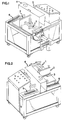
- Figs 1 and 2 are perspective views, illustrating an embodiment of the wrapping machine according to the invention.
- This machine comprises a unit 1 for feeding in a web, for instance a paper web, which is to form the wrappings, a cutting unit 2 for cutting the paper web into web sections, and a gluing unit 3 for applying a glue thread on the rear end portion of a web section.
- the machine is equipped with a wrapping unit 4 for wrapping or winding the web section round a roll of bags and applying the glue thread against the web section thus wound round the roll of bags. Accordingly, the machine provides the rolls of bags with closed wrappings, to be compared with the girdle of a cigar.
- the wrapping machine further comprises a unit 5 for supplying rolls of bags to a winding station in the wrapping unit 4.
- the rolls of bags may, for instance, be supplied directly from a separate machine for winding the bags into rolls, such as a spinner, or from an intermediate store of rolls of bags.
- the wrapping machine is equipped with a unit 6 for discharging the finished, wrapped rolls of bags.
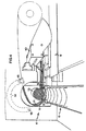
- Fig. 3 illustrates in more detail the unit 1 for feeding in a paper web 7.
- the feed-in unit 1 has an optical sensor 8, which senses the position of the paper web 7 along the feed-in unit 1.
- the feeding is so controlled that a suitable length of the paper web 7 is propelled, whereupon it is cut into a web section 9 by means of the cutting unit 2.
- An arm 10 which is movable in a direction perpendicular to the feed-in direction of the paper web, is adapted to convey the web section 9 from the feed-in unit 1 or cutting unit 2 to the wrapping unit 4.
- the arm 10 is provided with negative-pressure means (not shown), which by suction keep the web section 9 in place when this is being conveyed.
- the web section On its way from the cutting unit 2 to the wrapping unit 4, the web section passes a gluing unit (not shown), for instance a glue gun.
- the gluing unit is adapted to apply a glue thread to the rear end portion, as seen in the feed-in direction, of the passing web section 9. Consequently, this expedient conveyance of the web section 9 from the cutting unit 2 to the wrapping unit 4 permits the use of a stationary gluing unit, which enables a wrapping machine of simpler design.
- the illustrated embodiment of the wrapping unit 4 has two parallel, drivable and endless belts 11 forming two loops in the wrapping unit 4.
- the belts 11 may be driven in any suitable fashion, for instance with the aid of a driven belt wheel brought into engagement therewith.
- the wrapping unit 4 has two parallel, spaced-apart spindles, on which a number of support rollers 12 are fixedly mounted. These support rollers 12 are adapted to support a cylindrical roll of bags 13 fed into the wrapping unit 4.
- each spindle is provided with three support rollers 12, which are spaced apart along the spindle.
- the support rollers 12 are so arranged on the spindles as to accommodate between them the two parallel belts 11, which above the spindles extend essentially perpendicularly to the longitudinal direction of the rollers 12.
- An arcuate belt-guiding means 14 which is indicated by dashed lines in Fig. 4, is arranged in the wrapping unit 4.
- the one end portion of the guiding means 14 is rotatably mounted on a shaft 15, which is parallel to said spindles and is located outside the belt loops 11.
- a number of wedge-shaped guiding lugs 16 are provided on the other, free end portion of the guiding means 14.
- the respective belts 11 are accommodated in a carrier assembly (not shown) on the free end portion of the belt-guiding means 14.
- Each carrier assembly has at least one rotatable carrier and one end plate, between which extends the belt 11.
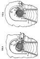
- the free, guiding-wedge-equipped end portion of the belt-guiding means 14 may, by pivoting the belt-guiding means 14 in the direction of the belt loops 11, be brought to the vicinity of the support rollers 12, as illustrated in Figs 5 and 6.
- the pair of belts 11 forms a flat feeder web 17.
- the belts 11 rest on a suction box generating a negative pressure between and round the pair of belts 11.
- the wrapping unit 4 further comprises a tensioning means (not shown), which is adapted to control the tensioning of the belts 11.
- This tensioning means may, for instance, comprise belt rollers which are applied against the belts 11 and which can be moved in the direction of the belts, so as to increase the tensioning thereof.
- the tensioning means should be adapted to be applied against that part of the belts 11 which is located at a distance from the feeder web 17, the support rollers 12 and the belt-guiding means 14, thereby to avoid that the belts 11 are dislodged during the tensioning procedure.
- the application of a wrapping round a roll of bags in the wrapping machine is so carried out that a web, which is to form the wrapping, is supplied and cut into web sections 9 of suitable length.
- the web section 9 is provided with a glue thread and is conveyed to the wrapping unit 4.
- a roll of bags 13 is fed into the wrapping unit 4 via the supply unit 5 for rolls of bags, whereupon the roll of bags 13 is arranged within the belt loops 11 and on the support rollers 12 (Fig. 4).
- the belts 11 then rest in the spaces between the support rollers 12 and are located at a distance from the circumferential surface of the roll of bags 13, thereby to obviate the risk of the roll of bags 13 being deformed when fed into the wrapping unit 4.
- a deformation of the roll of bags 13 might result in the web section 9 being obliquely applied or being applied with insufficient tension round the roll of bags 13.
- the feed-in direction of the roll of bags 13 is perpendicular to the winding plane, i.e. the geometric plane in which the web section 9 is wound round the roll of bags 13.
- the winding plane is vertical and parallel to the belt loops 11 in the wrapping unit 4.
- a glued web section 9 is placed on the feeder web 17 in front of the roll of bags 13.
- the web section is sucked towards the belts 11 under the action of the negative pressure generated by the suction box.
- the belt-guiding means 14 is pivoted in the direction of the belts 11, such that the latter, which are applied against the above-mentioned carriers at the free end portion of the belt-guiding means 14, are guided along a path round a substantial part of the circumference of the roll of bags 13 (Fig. 5).
- the belts 11 are increasingly tensioned with the aid of the tensioning means, such that the belts 11 are tensioned round the roll of bags 13 while being brought into engagement with the driven belt wheel.
- the belt loop 11 is driven clockwise in the wrapping unit 4, the roll of bags 13 beginning to rotate, as is indicated by an arrow in Fig. 6.
- the movement of the belts 11 results in a simultaneous displacement of the web section 9 placed on the feeder web 17 in the direction of the rotating roll of bags 13.
- the front end portion of the web section 9 is then brought into engagement with the circumferential surface of the rotating roll of bags 13, and is clamped between the belts 11 and said circumferential surface. Owing to simultaneous clamping and rotation, the web section 9 is then wound round the roll of bags 13.
- the belts 11 essentially enclosing the roll of bags 13 tension the web section 9 round the roll of bags 13 and also ensure that the glue thread is evenly applied against an opposing part of the wound-up web section 9. In this manner, it is ensured that the wrapping is fixed round the roll of bags 13 in a perfectly reliable fashion.
- the tensioning of the belts 11 is reduced, and the belts 11 and the roll of bags 13 thus cease to rotate.
- the belt-guiding means 14 is pivoted back to its initial position (shown in Fig. 4), its free end portion being displaced at a distance from the support rollers 12 and the roll of bags 13. Being accommodated in the free end portion of the belt-guiding means 14, also the belts 11 are moved away from the roll of bags 13 during this operation. Then, the wrapped roll of bags 13 is further conveyed by means of the discharging unit 6 for rolls of bags.
- Figs 7-9 schematically illustrate how a web section 9 is wound round a roll of bags 13.
- Fig. 7 shows a roll of bags 13 and a web section 9 which are located at a distance from one another.
- the one edge portion 18 of the web section 9 is disposed in parallel with the longitudinal direction of the roll of bags 13.
- a glue thread 19 is applied on the end portion of the web section 9 that faces away from the roll of bags 13.
- the roll of bags 13 is so oriented that its winding is opposite to its subsequent direction of rotation.
- Fig. 8 illustrates an intermediate position, in which the roll of bags 13 is rotated and the web section 9 is clamped against its circumferential surface. As a result, the web section 9 is wound round the roll of bags 13.
- the direction of rotation of the roll of bags is, in Fig. 8, indicated by an arrow round an axis of rotation (dashed lines).
- Fig. 9 illustrates a wrapped roll of bags
- the rear end portion of the web section 9 overlaps the front end portion.
- the length of the web section 9 has to exceed the circumference of the roll of bags 13.
- the web intended to form the wrappings round the rolls of bags need not be made of paper.
- other pliable materials such as plastic, may also be used.
- the web section may be connected to the web section wound round the roll of bags in optional fashion.
- the glue thread may, for instance, be replaced with one or more strips of tape, which are applied over the joint between the free rear end portion of the web section and the wound-up web section.
- endless belts described above may be replaced with a single broad belt or a plurality of narrow belts.
Landscapes
- Engineering & Computer Science (AREA)
- Mechanical Engineering (AREA)
- Making Paper Articles (AREA)
- Basic Packing Technique (AREA)
- Packaging Of Special Articles (AREA)
- Auxiliary Devices For And Details Of Packaging Control (AREA)
- Replacement Of Web Rolls (AREA)
Description
Claims (9)
- A device for applying a wrapping round a cylindrical roll of bags (13), said device comprising a feeding unit (1) for a web (7) that is to form the wrapping; a cutting unit (2) for cutting the web (7) into web sections (9) of suitable length; a unit (5) for feeding rolls of bags (13) to a winding station; a wrapping unit (4) for winding a web section (9) round the roll of bags (13) in the winding station, said wrapping unit (4) comprising a means (17) for feeding the front end portion of the web section (9), as seen in the feeding direction, to a site adjacent to the circumferential surface of the roll of bags (13), a means (11, 14) adapted to grip the roll of bags (13) and the adjacent front end portion of the web section (9) as well as to rotate the roll of bags (13) about its longitudinal axis so as to wind the web section (9) round it, and means for connecting the rear end portion of the web section (9) to the web section (9) wound round the roll of bags (13); and a unit (6) for discharging wrapped rolls of bags (13), characterised in that the gripping means (11, 14) adapted to rotate the roll of bags comprises at least one endless belt (11), a mechanism for driving the belt (11), and an operating means (14) for bringing the belt (11) into engagement with the circumferential surface of the roll of bags (13), and the belt or belts (11) are located at a distance from the circumferential surface of the roll of bags (13) when the latter is being fed into the wrapping unit (4).
- A device as set forth claim 1, wherein the roll of bags (13) is so oriented in the wrapping unit (4) that the winding of the roll of bags (13) is opposite to the direction of rotation of the roll of bags (13).
- A device as set forth in any one of the preceding claims, wherein the gripping means (11, 14) adapted to rotate the bag of rolls comprises at least one guiding wedge (16), which is adapted to guide the front end portion of the web section (9) round the roll of bags (13) during the rotation of the latter.
- A device as set forth in any one of the preceding claims, wherein the feeding means (17) comprises negative-pressure means adapted to keep the web section (9) in place by suction when the latter is being propelled.
- A device as set forth in any one of the preceding claims, wherein the feed-in unit (1) comprises an arm (10) which is movable in a direction perpendicular to the feed-in direction of the web (7) and which is adapted to convey the web section (9) from the cutting unit (2) to the wrapping unit (4).
- A method for applying a wrapping round a cylindrical roll of bags (13), comprising the steps of cutting a web (7), which is to form the wrapping, into web sections (9) of suitable length; introducing the web section (9) into a wrapping unit (4); feeding the one end portion of the web section (9) to a roll of bags (13) in the wrapping unit (4); applying said end portion of the web section (9) on the outside of the roll of bags (13) and clamping it there; rotating the roll of bags (13) about its longitudinal axis, such that the web section (9) is wound round the roll of bags (13); and connecting the other end portion of the web section (9) to the web section (9) wound round the roll of bags, thereby creating a wrapping, characterised in that the roll of bags (13) is fed into the wrapping unit (4) and is so arranged within an endless belt (11) associated with the wrapping unit (4) that the belt (11) is located at a distance from the circumferential surface of the roll of bags (13).
- A method as set forth in claim 6, wherein the web section (9) is given a length exceeding the circumference of the roll of bags (13), and the web section (9) is wound round the roll of bags (13) in such a manner that the other end portion of the web section (9) overlaps said one end portion of the web section (9).
- A method as set forth in claim 6 or 7, wherein the roll of bags (13) is so oriented in the wrapping unit (4) that the winding of the roll of bags (13) is opposite to the direction of rotation of the roll of bags (13).
- A method as set forth in claim 6, 7 or 8, wherein the web section (9) is conveyed to the wrapping unit (4) in a direction perpendicular to the feed-in direction of the web (7).
Applications Claiming Priority (3)
| Application Number | Priority Date | Filing Date | Title |
|---|---|---|---|
| SE9500643A SE506084C2 (en) | 1995-02-21 | 1995-02-21 | Apparatus and method for applying wraps to cylindrical bag rolls |
| SE9500643 | 1995-02-21 | ||
| PCT/SE1996/000230 WO1996026112A1 (en) | 1995-02-21 | 1996-02-20 | Device and method in wrapping machine |
Publications (2)
| Publication Number | Publication Date |
|---|---|
| EP0810947A1 EP0810947A1 (en) | 1997-12-10 |
| EP0810947B1 true EP0810947B1 (en) | 2000-03-22 |
Family
ID=20397313
Family Applications (1)
| Application Number | Title | Priority Date | Filing Date |
|---|---|---|---|
| EP96904420A Expired - Lifetime EP0810947B1 (en) | 1995-02-21 | 1996-02-20 | Device and method in wrapping machine |
Country Status (8)
| Country | Link |
|---|---|
| US (1) | US5927047A (en) |
| EP (1) | EP0810947B1 (en) |
| JP (1) | JPH11500691A (en) |
| DE (1) | DE69607326T2 (en) |
| DK (1) | DK0810947T3 (en) |
| ES (1) | ES2143753T3 (en) |
| SE (1) | SE506084C2 (en) |
| WO (1) | WO1996026112A1 (en) |
Families Citing this family (8)
| Publication number | Priority date | Publication date | Assignee | Title |
|---|---|---|---|---|
| ITTO20020112A1 (en) * | 2002-02-08 | 2003-08-08 | Casmatic Spa | ,, APPARATUS TO WRAP A BAND ON A RESPECTIVE MATERIAL ROLL ,, |
| EP1571086A1 (en) * | 2004-03-05 | 2005-09-07 | Kba-Giori S.A. | Banding system for piled products and process |
| US7464516B2 (en) * | 2006-12-07 | 2008-12-16 | Schweitzer-Manduit International, Inc. | Over-wrap apparatus and method for a bobbin and paper |
| CN105438521A (en) * | 2015-11-30 | 2016-03-30 | 芜湖凯尔电气科技有限公司 | Battery surface packaging device |
| CN105752423B (en) * | 2016-04-07 | 2018-03-06 | 河南省科琦游乐设备有限公司 | Abdominal belt movable type centreless mica wrappingmachine |
| WO2018069404A1 (en) | 2016-10-14 | 2018-04-19 | Roll-O-Matic A/S | A wrapping device for a machine for winding-up a web material, and a machine for winding-up a web material including the wrapping device |
| CN111619847B (en) * | 2020-06-08 | 2021-11-09 | 永嘉跃龙密封件有限公司 | Sealing washer equipment for packing |
| CN115571412B (en) * | 2022-10-26 | 2025-04-29 | 福建虞牌实业有限公司 | A tape winding machine for umbrella poles |
Family Cites Families (16)
| Publication number | Priority date | Publication date | Assignee | Title |
|---|---|---|---|---|
| US2048042A (en) * | 1935-05-06 | 1936-07-21 | Robert C Wedge | Wrapping machine |
| US3013367A (en) * | 1956-05-03 | 1961-12-19 | St Clair Specialty Mfg Co | System of making coreless rolls |
| DE2065102C3 (en) * | 1970-01-22 | 1975-07-17 | Guenther Dr.-Ing. 4800 Bielefeld Schick | Device for wrapping cylindrical objects |
| FI57564C (en) * | 1979-02-13 | 1980-09-10 | Waertsilae Oy Ab | ANORDING FROM THE ROLLING STOCK |
| SE454871B (en) * | 1982-10-20 | 1988-06-06 | Stretch Emballering Ab | PLANT FOR PACKAGING |
| DE3314289C2 (en) * | 1983-04-20 | 1987-01-02 | Grünzweig + Hartmann und Glasfaser AG, 6700 Ludwigshafen | Method for wrapping a rotating bale of wrapping material, in particular of a laminated mineral fibre web, with a protective web for packaging, and device for carrying out the method |
| SU1137019A1 (en) * | 1983-08-09 | 1985-01-30 | Научно-Исследовательский Институт Тяжелого Машиностроения Производственного Объединения "Уралмаш" | Machine for packing coils into metal wrapping |
| US4694959A (en) * | 1986-01-29 | 1987-09-22 | Minigrip, Inc. | Maintaining single link chain bags against skewing |
| SE452144B (en) * | 1986-11-05 | 1987-11-16 | Fas Converting Machinery Ab | PROCEDURE AND MACHINE FOR MAKING PASSENGER ROLLS |
| SE452131B (en) * | 1986-11-05 | 1987-11-16 | Fas Converting Machinery Ab | APPARATUS OF PASCHMASK FOR THE PREFERRATION PERFORMING LINES AND WELDING LINES |
| JPH07115686B2 (en) * | 1988-12-05 | 1995-12-13 | 富士写真フイルム株式会社 | Packaging equipment |
| US5046298A (en) * | 1990-05-08 | 1991-09-10 | Haines And Emerson, Inc. | Method and apparatus for wrapping a roll with stretch wrap |
| FI89149C (en) * | 1991-02-12 | 1996-09-11 | Valmet Paper Machinery Inc | Method and apparatus for packaging rolls, in particular paper rolls, with packaging wrappers |
| US5282345A (en) * | 1991-07-01 | 1994-02-01 | Xerox Corporation | Apparatus for handling a sheet of separator material |
| JP2665703B2 (en) * | 1992-04-13 | 1997-10-22 | 株式会社シンワコーポレーション | Exterior method of cylindrical body |
| US5469688A (en) * | 1993-07-26 | 1995-11-28 | Michael D. Dunbar | Method for wrapping silverware in a napkin |
-
1995
- 1995-02-21 SE SE9500643A patent/SE506084C2/en not_active IP Right Cessation
-
1996
- 1996-02-20 ES ES96904420T patent/ES2143753T3/en not_active Expired - Lifetime
- 1996-02-20 DE DE69607326T patent/DE69607326T2/en not_active Expired - Fee Related
- 1996-02-20 WO PCT/SE1996/000230 patent/WO1996026112A1/en not_active Ceased
- 1996-02-20 DK DK96904420T patent/DK0810947T3/en active
- 1996-02-20 JP JP8525617A patent/JPH11500691A/en active Pending
- 1996-02-20 EP EP96904420A patent/EP0810947B1/en not_active Expired - Lifetime
- 1996-02-20 US US08/894,529 patent/US5927047A/en not_active Expired - Fee Related
Also Published As
| Publication number | Publication date |
|---|---|
| DK0810947T3 (en) | 2000-07-10 |
| EP0810947A1 (en) | 1997-12-10 |
| ES2143753T3 (en) | 2000-05-16 |
| SE9500643L (en) | 1996-08-22 |
| DE69607326T2 (en) | 2000-07-27 |
| DE69607326D1 (en) | 2000-04-27 |
| SE9500643D0 (en) | 1995-02-21 |
| JPH11500691A (en) | 1999-01-19 |
| WO1996026112A1 (en) | 1996-08-29 |
| SE506084C2 (en) | 1997-11-10 |
| US5927047A (en) | 1999-07-27 |
Similar Documents
| Publication | Publication Date | Title |
|---|---|---|
| US4856725A (en) | Web winding machine and method | |
| CA1307512C (en) | Web winding machine and method | |
| US4962897A (en) | Web winding machine and method | |
| KR100307429B1 (en) | Rewinder incorporating a tail sealer | |
| EP1273540B1 (en) | Method and apparatus for separating a web at a line of weakness | |
| US5131593A (en) | Splicing technique and apparatus | |
| JPH05262307A (en) | Process and device for avoiding downtime on packaging machine | |
| CA2275791C (en) | Apparatus and method for wrapping compressible articles with a web-like wrapping material | |
| GB2181414A (en) | Splicing webs of packaging material | |
| EP0415377B1 (en) | Machine and method for overwrapping cylindrical articles | |
| JPS6118655A (en) | Roll winding machine for paper web, etc. | |
| US5927047A (en) | Device and method in wrapping machine | |
| JPS6343291B2 (en) | ||
| US4720320A (en) | Apparatus for splicing a trailing end of a web from a depleted coil to the leading end of a fresh coil | |
| JPS63232115A (en) | Packaging method and device for pressure-sensitive sheet material rolls | |
| US5428941A (en) | Apparatus for winding a printed product and a protective wrapping into a roll | |
| EP0812792B1 (en) | Web splicing apparatus | |
| US5028011A (en) | Method and apparatus for winding and crosscutting a running fabric web | |
| US6298634B1 (en) | Process and device for producing a wound roll that is wrapped on its circumference, and the wound roll | |
| US4936459A (en) | Interleaved spiral wrapping of foam product and stretch film for packaging carbonless paper rolls | |
| JPH06191697A (en) | Method and device for rolling web on spool | |
| EP0431922B1 (en) | Wrapping roll-like articles | |
| US5983606A (en) | Device and method for packaging a web roll with a packaging sheet | |
| WO2000068128A1 (en) | Device for joining together two packaging films for packaging machines of the 'flow-pack' type | |
| US6044619A (en) | Reel slitting device and method |
Legal Events
| Date | Code | Title | Description |
|---|---|---|---|
| PUAI | Public reference made under article 153(3) epc to a published international application that has entered the european phase |
Free format text: ORIGINAL CODE: 0009012 |
|
| 17P | Request for examination filed |
Effective date: 19970718 |
|
| AK | Designated contracting states |
Kind code of ref document: A1 Designated state(s): BE DE DK ES FR GB IT SE |
|
| 17Q | First examination report despatched |
Effective date: 19990330 |
|
| GRAG | Despatch of communication of intention to grant |
Free format text: ORIGINAL CODE: EPIDOS AGRA |
|
| GRAG | Despatch of communication of intention to grant |
Free format text: ORIGINAL CODE: EPIDOS AGRA |
|
| GRAH | Despatch of communication of intention to grant a patent |
Free format text: ORIGINAL CODE: EPIDOS IGRA |
|
| GRAH | Despatch of communication of intention to grant a patent |
Free format text: ORIGINAL CODE: EPIDOS IGRA |
|
| GRAA | (expected) grant |
Free format text: ORIGINAL CODE: 0009210 |
|
| AK | Designated contracting states |
Kind code of ref document: B1 Designated state(s): BE DE DK ES FR GB IT SE |
|
| PG25 | Lapsed in a contracting state [announced via postgrant information from national office to epo] |
Ref country code: SE Free format text: THE PATENT HAS BEEN ANNULLED BY A DECISION OF A NATIONAL AUTHORITY Effective date: 20000322 |
|
| ITF | It: translation for a ep patent filed | ||
| REF | Corresponds to: |
Ref document number: 69607326 Country of ref document: DE Date of ref document: 20000427 |
|
| REG | Reference to a national code |
Ref country code: ES Ref legal event code: FG2A Ref document number: 2143753 Country of ref document: ES Kind code of ref document: T3 |
|
| REG | Reference to a national code |
Ref country code: DK Ref legal event code: T3 |
|
| ET | Fr: translation filed | ||
| PLBE | No opposition filed within time limit |
Free format text: ORIGINAL CODE: 0009261 |
|
| STAA | Information on the status of an ep patent application or granted ep patent |
Free format text: STATUS: NO OPPOSITION FILED WITHIN TIME LIMIT |
|
| PG25 | Lapsed in a contracting state [announced via postgrant information from national office to epo] |
Ref country code: GB Free format text: LAPSE BECAUSE OF NON-PAYMENT OF DUE FEES Effective date: 20010220 |
|
| PG25 | Lapsed in a contracting state [announced via postgrant information from national office to epo] |
Ref country code: BE Free format text: LAPSE BECAUSE OF NON-PAYMENT OF DUE FEES Effective date: 20010228 |
|
| 26N | No opposition filed | ||
| BERE | Be: lapsed |
Owner name: FAS CONVERTING MACHINERY A.B. Effective date: 20010228 |
|
| GBPC | Gb: european patent ceased through non-payment of renewal fee |
Effective date: 20010220 |
|
| PG25 | Lapsed in a contracting state [announced via postgrant information from national office to epo] |
Ref country code: DE Free format text: LAPSE BECAUSE OF NON-PAYMENT OF DUE FEES Effective date: 20011201 |
|
| PG25 | Lapsed in a contracting state [announced via postgrant information from national office to epo] |
Ref country code: FR Free format text: LAPSE BECAUSE OF NON-PAYMENT OF DUE FEES Effective date: 20020430 |
|
| REG | Reference to a national code |
Ref country code: FR Ref legal event code: ST |
|
| PGFP | Annual fee paid to national office [announced via postgrant information from national office to epo] |
Ref country code: ES Payment date: 20030220 Year of fee payment: 8 |
|
| PGFP | Annual fee paid to national office [announced via postgrant information from national office to epo] |
Ref country code: DK Payment date: 20030226 Year of fee payment: 8 |
|
| PG25 | Lapsed in a contracting state [announced via postgrant information from national office to epo] |
Ref country code: ES Free format text: LAPSE BECAUSE OF NON-PAYMENT OF DUE FEES Effective date: 20040221 |
|
| PG25 | Lapsed in a contracting state [announced via postgrant information from national office to epo] |
Ref country code: DK Free format text: LAPSE BECAUSE OF NON-PAYMENT OF DUE FEES Effective date: 20040301 |
|
| REG | Reference to a national code |
Ref country code: DK Ref legal event code: EBP |
|
| PG25 | Lapsed in a contracting state [announced via postgrant information from national office to epo] |
Ref country code: IT Free format text: LAPSE BECAUSE OF NON-PAYMENT OF DUE FEES;WARNING: LAPSES OF ITALIAN PATENTS WITH EFFECTIVE DATE BEFORE 2007 MAY HAVE OCCURRED AT ANY TIME BEFORE 2007. THE CORRECT EFFECTIVE DATE MAY BE DIFFERENT FROM THE ONE RECORDED. Effective date: 20050220 |
|
| REG | Reference to a national code |
Ref country code: ES Ref legal event code: FD2A Effective date: 20040221 |
|
| PG25 | Lapsed in a contracting state [announced via postgrant information from national office to epo] |
Ref country code: FR Free format text: LAPSE BECAUSE OF NON-PAYMENT OF DUE FEES Effective date: 20010228 |