EP0810898B1 - Vaporizer and liquid delivery system using same - Google Patents
Vaporizer and liquid delivery system using same Download PDFInfo
- Publication number
- EP0810898B1 EP0810898B1 EP96904630A EP96904630A EP0810898B1 EP 0810898 B1 EP0810898 B1 EP 0810898B1 EP 96904630 A EP96904630 A EP 96904630A EP 96904630 A EP96904630 A EP 96904630A EP 0810898 B1 EP0810898 B1 EP 0810898B1
- Authority
- EP
- European Patent Office
- Prior art keywords
- disks
- liquid
- vaporizer
- further characterised
- liquid vaporizer
- Prior art date
- Legal status (The legal status is an assumption and is not a legal conclusion. Google has not performed a legal analysis and makes no representation as to the accuracy of the status listed.)
- Expired - Lifetime
Links
Images


Classifications
-
- B—PERFORMING OPERATIONS; TRANSPORTING
- B01—PHYSICAL OR CHEMICAL PROCESSES OR APPARATUS IN GENERAL
- B01B—BOILING; BOILING APPARATUS ; EVAPORATION; EVAPORATION APPARATUS
- B01B1/00—Boiling; Boiling apparatus for physical or chemical purposes ; Evaporation in general
-
- B—PERFORMING OPERATIONS; TRANSPORTING
- B01—PHYSICAL OR CHEMICAL PROCESSES OR APPARATUS IN GENERAL
- B01D—SEPARATION
- B01D1/00—Evaporating
- B01D1/22—Evaporating by bringing a thin layer of the liquid into contact with a heated surface
- B01D1/221—Composite plate evaporators
-
- B—PERFORMING OPERATIONS; TRANSPORTING
- B01—PHYSICAL OR CHEMICAL PROCESSES OR APPARATUS IN GENERAL
- B01D—SEPARATION
- B01D1/00—Evaporating
-
- B—PERFORMING OPERATIONS; TRANSPORTING
- B01—PHYSICAL OR CHEMICAL PROCESSES OR APPARATUS IN GENERAL
- B01D—SEPARATION
- B01D1/00—Evaporating
- B01D1/0011—Heating features
-
- B—PERFORMING OPERATIONS; TRANSPORTING
- B01—PHYSICAL OR CHEMICAL PROCESSES OR APPARATUS IN GENERAL
- B01D—SEPARATION
- B01D3/00—Distillation or related exchange processes in which liquids are contacted with gaseous media, e.g. stripping
- B01D3/34—Distillation or related exchange processes in which liquids are contacted with gaseous media, e.g. stripping with one or more auxiliary substances
- B01D3/343—Distillation or related exchange processes in which liquids are contacted with gaseous media, e.g. stripping with one or more auxiliary substances the substance being a gas
- B01D3/346—Distillation or related exchange processes in which liquids are contacted with gaseous media, e.g. stripping with one or more auxiliary substances the substance being a gas the gas being used for removing vapours, e.g. transport gas
-
- F—MECHANICAL ENGINEERING; LIGHTING; HEATING; WEAPONS; BLASTING
- F24—HEATING; RANGES; VENTILATING
- F24V—COLLECTION, PRODUCTION OR USE OF HEAT NOT OTHERWISE PROVIDED FOR
- F24V99/00—Subject matter not provided for in other main groups of this subclass
Definitions
- the present invention relates to liquid vaporizers and more particularly to a liquid vaporizer in which vaporization of a liquid is accelerated by the use of a novel arrangement of coaxially-aligned, thin, flat, thermally-conductive disks having different diameters, and by the introduction of a gas in a novel and useful way.
- Various processes utilize reactive gases carefully introduced into a processing chamber.
- precisely controlled amounts of a processing gas are often carefully introduced into a processing chamber for reaction with certain material(s) on a wafer to produce desired structures or devices.
- Some of these gases would be liquids at the process temperature and pressure and are generally classified as low vapor pressure liquids. It is not uncommon for a process to be run at a temperature and pressure where one of the required materials will not exist in purely gaseous form.
- the typical method of providing such materials in vapor form uses a device referred to as a bubbler.
- a bubbler is a heated container partially filled with the liquid in question.
- a gas is bubbled up through the liquid and combines with the vapor from the liquid.
- the resulting gas/vapor mixture is then introduced into the process. Bubblers are not ideally suited to the precise control required for introduction of vapor to a processing chamber because of cumbersome plumbing and heating problems associated with those devices.
- Flash vaporizers are disclosed, for example, in U.S. Patent Nos. 5,361,800 and 5,371,828 to Ewing, currently assigned to the assignee of the present invention.
- the disclosed vaporizers include a heater assembly in thermal contact with a stack of thermally conductive, thin, flat disks biased together with a spring-loaded anvil. The heater assembly heats the disks to a temperature in excess of the flash point of the liquid to be vaporized at the process pressure.
- Liquid is supplied from a pumping system through a tube passing through the center of the coaxially stacked disks and is forced between the parallel disks, against the bias of the spring-loaded anvil.
- the liquid is heated by the hot surfaces of the disks to a temperature above its flash point and is vaporized.
- evaporation means the conversion of a liquid to a vapor by the addition of latent heat.
- Volatilization or “volatilization” means the conversion of a liquid to a vapor by the application of heat and/or by reducing the pressure on the material.
- This vaporization process can be further optimized by increasing the vaporization surface area.
- the liquid should form an extremely thin film on the vaporization surfaces, such as the heated disks in the Ewing patents.
- a large vaporization area and a means for accelerating the vaporization would be a desirable and beneficial combination.
- US-A-414207 discloses a steam boiler which includes small diameter plates interleaved with larger diameter plates.
- Another object of the present invention is to provide an improved liquid vaporizer over those described in the above-noted prior art.
- Another object of the present invention is to accelerate the vaporization rate of a liquid in a vaporizer.
- Yet another object of the present invention is to increase the ability of the liquid to form a film on the surfaces of the heated disks in the flash vaporizer of the type described in U.S. Patent Nos. 5,361,800 and 5,371,828.
- Still another object of the present invention is to provide a vaporizer which can be used with or without an auxiliary gas.
- liquid vaporizer which provides a precisely controlled amount of liquid material in vapor form.
- a liquid vaporizer including:
- an apparatus for delivering a liquid in vapour form at a continuous and constant volumetric rate comprising, in combination:
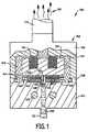
- the liquid vaporizer of the present invention comprises a block assembly 102 including a heating block 104 and a cover block 106 with a suitable seal 108 secured therebetween.
- the blocks 104 and 106 and seal 108 are shaped and secured together so as to define an enclosed vaporizing chamber 110 having an inlet 112, preferably formed through the heater block 104, for the introduction of a liquid 150 thereto, and an outlet 114 from which vapor 160 exits the chamber.
- the vaporizer 100 further includes a stack of coaxially aligned, thermally-conductive, thin, flat disks 120.
- the disks include central apertures 122, all of which are axially aligned in the stack and preferably mounted coaxially with the inlet port 112.
- the vaporizer 100 also includes means, in the form of one or more compression springs 124 and an anvil 126, for axially compressing the disks 120 together.
- the anvil 126 preferably physically and thermally contacts substantially the entire surface of the upper disk 120 of the stack and functions to insure the application of a uniform axial compression force on the disks exerted by the springs 124.
- the anvil 126 is a relatively massive structure and is preferably made of a thermally conductive material which will help retain heat in the disks so as not to dissipate heat appreciably from the disks.
- the compression springs 124 should also be made of a thermally conductive material because they are in thermal and physical contact with the anvil 126.
- a tube 128 is disposed within the apertures 122 and has radially directed apertures 130 for directing liquid 150 from the inlet 112 to the inner circumferential edges of the central apertures 122 so that the liquid can be forced between the disks against the bias of the springs 124.
- the vaporizer 100 also includes a heating unit 132, such as a heating coil, for heating the heating block 104 and the disks 120 so as to heat liquid 150 passing through the inlet 112 and between the disks 120 to a temperature sufficient to vaporize the liquid.
- the heating unit 132 can include any type of suitable heating device and can include, for example, a resistive heating coil, which is preferably embedded in and in thermal contact with the heating block 104 so that heat is distributed as evenly as possible through the disks 120.
- the heating unit 132 is connected to a source of power (not shown) and should be capable of heating the disks 120 to a range of temperatures at which the liquid can be converted to a vapor.
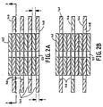
- the stack of coaxially aligned, thermally conductive, thin, flat disks 120 comprises a first plurality of larger disks 140 having a first diameter D 1 and a second plurality of smaller disks 142 having a second diameter D 2 so that the diameter D 1 is larger than D 2 .
- the total number of disks can vary depending on the rate at which liquid is to be vaporized. Further, the thickness of all the disks, both small and large, should be approximately the same, although it should be appreciated that the thicknesses can vary as, for example, the larger disks could be thicker or thinner than the smaller disks.
- the diameters of the larger and smaller disks 140 and 142, respectively, are preferably each relatively great in comparison to the thickness, t, of the disks, with the ratios of the larger diameter D 1 to the thickness t and the smaller diameter D 2 to the thickness t being in the order of 1000:1, although these ratios can clearly vary.
- each disk from the first plurality of larger diameter disks 140 is adjacent to and in contact with at least one smaller diameter disk 142.
- FIGURES 2A and 2B illustrate two of any number of possible arrangements of disks 140 and 142 within the vaporizer 100.
- the larger and smaller disks are stacked in an alternating fashion so that the disks alternate (i.e., large, small, large, small, large, small, etc.).
- This arrangement separates the larger diameter disks 140 from one another by a distance t, the thickness of a single smaller diameter disk.
- the disks at each end of the stack should be smaller for reasons which will become more evident hereinafter.
- the disks can also be arranged, for example, so that a single larger diameter disk 140 is sandwiched between two smaller diameter disks 142, the smaller diameter disks of each sandwiched set being adjacent to one another.
- the disks can also be arranged, for example, so that a single larger diameter disk 140 is sandwiched between two smaller diameter disks 142, the smaller diameter disks of each sandwiched set being adjacent to one another.
- the vaporization areas designated 144, provided by virtue of the spacings created by the presence of the smaller diameter disks 142 in the stack of disks 120.
- each of the larger diameter disks 140 includes at least one and preferably a plurality of apertures 146 for accelerating vaporization of the liquid 150 from the heated surfaces of the disks, in particular from the portion of the heated surfaces of the larger diameter disks 140 in the vaporization areas 144.
- the larger diameter disks 140 each include a plurality of apertures 146 spaced around and radially spaced from the center of each of the disks.
- the apertures 146 are closely spaced a distance S apart from one another on each of the larger diameter disks 140 around an aperture circle of diameter C , as shown in FIGURE 3.
- the apertures 146 are preferably equidistantly spaced from the center of the disk 140 by a distance of C/2 and are preferably separated from one another by a distance S which is less than the diameter or width d of the apertures 146.
- the diameter C of the aperture circle on the larger diameter disk 140 is greater than the diameter D 2 of the smaller diameter disk 142 by at least d so that the apertures 146 are disposed entirely in the respective vaporization areas 144.
- the apertures 146 can be of any shape that has at least a width dimension of d .
- the apertures 146 are circular openings having a diameter d .
- they can be squares, ovals, crescents, triangles, slits, or any other shape that meets the above criterion.
- the apertures 146 in each of the respective larger diameter disks 140 are sufficiently closely spaced so that a plurality of channels 148 extends in a generally transverse direction through the parallel stacked disks around the outside periphery of the smaller disks 142.
- the diameter D 1 of the larger diameter disks 140 is preferably larger than the diameter D 2 of the smaller diameter disks 142 by a predetermined amount.
- the difference in sizes of the two pluralities of disks is believed to be critical to the invention, because accelerated vaporization occurs substantially all on those portions of the surfaces of the larger diameter disks 140 which extend beyond the outer periphery of the smaller diameter disks 142, thereby defining the vaporization areas 144.
- the diameter D 1 of the larger diameter disk 140 is greater than or equal to the sum of the diameter D 2 of the smaller diameter disk 142 and eight times the aperture width dimension d of apertures 146, or D 1 ⁇ D 2 + 8d. This relationship between the diameters of the larger and smaller disks depends on, among other things, the characteristics of the liquid to be vaporized, the temperature at which vaporization is to occur, and the velocity of the gas flow over the vaporization areas.
- the diameter of the aperture circle C is greater than or equal to the sum of the diameter D 2 of the smaller diameter disk 142 and the aperture width dimension d, but less than or equal to the difference of the diameter D 1 of the larger diameter disk 140 and the aperture width dimension d, or D 2 + d ⁇ C ⁇ D 1 - d.
- Accelerated vaporization is facilitated by: 1) the number and placement of the apertures 146 on each larger diameter disk 140 at a distance of not less than C /2 from the center of the disk, the diameter C of the aperture circle being greater than (by an amount equal to "d") or at least equal to the diameter D 2 of the smaller diameter disk 142, and 2) means 170 for establishing a liquid film on at least a portion of the surfaces of the larger diameter disks 140.
- liquid film establishing means 170 preferably includes means for transporting a gas 180 to the vaporization areas 146.
- the liquid film establishing means includes a gas inlet 172 formed, for example, in the heating block 104 and means, such as a channel or passageway 174 provided in the heating block, for conducting a gas 180 from a gas source (not shown) outside of the vaporizing chamber 110 to the vaporization areas 144.
- the gas 180 flows into the vaporizing chamber 110 via channel 174, through the apertures 146 in the larger diameter disks 140 and thus through the transverse channels 148 into the vaporization areas 144, where the gas 180 moves radially outward from the apertures 146 along the surfaces of the larger diameter disks 140 in the areas 144 to the edges of the larger diameter disks, as illustrated by the arrows in the enlarged detail view of the vaporizer in FIGURE 5.
- annular well 182 (seen best in FIGURE 5) having an inner diameter of D 2 and an outer diameter of (D 2 + d ) and coaxially aligned with the disks is in fluid communication with the passageway 174 so as to form an inlet plenum for the gas 180.
- the result is an increase in the rate at which the liquid 150 can be vaporized.
- the gas 180 increases the vaporization rate by accelerating the removal of vapor molecules from above the surface of the liquid.
- the gas 180 is transmitted through the heating block 104 it is preferably heated by the heating unit 132 prior to contacting the disks 140, so as to minimize heat dissipation from the disks.
- the gas 180 can be any gas, regardless of its inertness, corrosivity or combustibility. Indeed, the selection of the gas will depend greatly on the particular liquid which is to be vaporized, as well as on the process parameters. For example, the gas 180 could be selected to be chemically reactive with a particular liquid 150 to facilitate the vaporization of the liquid.
- FIGURE 6 An apparatus for delivering a liquid in vapor form at a continuous and constant volumetric rate is illustrated schematically in FIGURE 6.
- the apparatus includes a liquid vaporizer 100 as described previously, and a positive displacement pump system 22 coupled to the inlet port 112 of the evaporator vaporizer 100.
- the positive displacement pump system 22 includes a controller 36 which controls the sequence and operation of the various pumps and valves in the pump system to deliver a liquid 150 to the evaporator vaporizer 100 at a substantially continuous-and constant volumetric rate and pressure.
- a detailed description of the operation of a preferred positive displacement pump system 22 in connection with a vaporizer is described in U.S. Patents 5,361,800 and 5,371,828 to Ewing.
Landscapes
- Chemical & Material Sciences (AREA)
- Chemical Kinetics & Catalysis (AREA)
- Engineering & Computer Science (AREA)
- Physics & Mathematics (AREA)
- Thermal Sciences (AREA)
- Combustion & Propulsion (AREA)
- Mechanical Engineering (AREA)
- General Engineering & Computer Science (AREA)
- Chemical Vapour Deposition (AREA)
- Vaporization, Distillation, Condensation, Sublimation, And Cold Traps (AREA)
- Feeding, Discharge, Calcimining, Fusing, And Gas-Generation Devices (AREA)
- Filling Or Discharging Of Gas Storage Vessels (AREA)
Description
Claims (16)
- A liquid vaporizer (100) including:means (102) for providing an enclosed vaporizing chamber (110) having an inlet (112) and an outlet (114);a vaporization area (144) provided by a stack of coaxially-aligned, thermally-conductive, thin, flat disks (120) which comprises a first plurality of larger diameter disks (140) of a first diameter D1 stacked with a second plurality of smaller diameter disks (142) of a second diameter D2 and that are positioned within said chamber (110) between said inlet (112) and said outlet (114) so that a liquid (150) entering said inlet (112) is forced between adjacent disks (120) of said stack and into the vaporization area (144) so as to vaporize said liquid (150) into a vapor prior to exiting said outlet (114);biasing means (126) for axially compressing the disks (120) of said stack together; andheating means (132) for heating the disks (120) to a temperature sufficient to vaporize said liquid (150) characterised in thatthe vaporization area (144) is provided by the portions of the surfaces of the larger diameter disks (140) which extend beyond the outer periphery of the smaller diameter disks (141).
- A liquid vaporizer (100) as claimed in claim 1, further characterised in that each disk (140, 142) of each of said pluralities is adjacent to at least one disk (142, 140) of the other plurality.
- A liquid vaporizer (100) as claimed in claim 1 or 2, further characterised in that the biasing means (126) for axially compressing the disks (120) together comprises a spring-biased anvil.
- A liquid vaporizer (100) as claimed in any one of the preceding claims, further characterised in that the heating means (132) comprises a heating unit thermally coupled to at least one of the disks (120).
- A liquid vaporizer (100) as claimed in any one of the preceding claims, further characterised in that each larger diameter disk (140) includes at least one aperture (146).
- A liquid vaporizer (100) as claimed in claim 5, further characterised in that each disk (140) of said first plurality further includes a plurality of apertures (146) radially spaced from the center of said disk (140).
- A liquid vaporizer (100) as claimed in claim 6, further characterised in that the apertures (146) are spaced on the disk (140) around an aperture circle having a diameter "C" and that each of the apertures (146) has a width "d" and that the spacing "S" between adjacent apertures is not greater than d/2.
- A liquid vaporizer (100) as claimed in claim 7, further characterised in that said apertures (146) are radially spaced from the center of said disk (140) at said distance C/2 so that C is not less than D2 + d.
- A liquid vaporizer (100) as claimed in claim 8, further characterised in that D2 + d ≤ C ≤ D1 - d.
- A liquid vaporizer (100) as claimed in any one of claims 6 to 9, further characterised in that the apertures (146) comprise circular openings having a diameter d.
- A liquid vaporizer (100) as claimed in any one of the preceding claims, further characterised in that the liquid vaporizer (100) further includes means (170) for establishing a liquid film on at least a portion (144) of the surfaces of the disks (140) of said first plurality and for accelerating the vaporization of said liquid (150).
- A liquid vaporizer (100) as claimed in claim 11, further including a gas inlet port (172) of said chamber, wherein the means (170) for establishing a liquid film on at least a portion (144) of the surfaces of the larger diameter disks (140) and for accelerating the vaporization of the liquid (150) comprises means (174) for conducting a gas (180) from a source of gas coupled to the gas inlet port (172) of the chamber.
- A liquid vaporizer (100) as claimed in claim 12, further characterised in that the gas (180) flows into the chamber through the apertures (146) in the disks (140) of said first plurality and radially outward along the surfaces of the larger diameter disks (140) to the edges thereof.
- A liquid vaporizer (100) as claimed in claim 13, further characterised in that the gas (180) is heated by said heating means (132) before said gas (180) contacts said disks (140).
- An apparatus for delivering a liquid in vapour form at a continuous and constant volumetric rate, said apparatus comprising, in combination:a liquid vaporizer (100) as claimed in any one of the preceding claims, anda positive displacement pump system (22) coupled to said inlet (112) of said vaporization chamber (110) for delivering liquid (150) to said evaporator at a substantially continuous and constant volumetric rate and pressure.
- An apparatus as claimed in claim 15, further characterised in that said liquid vaporizer (100) further includes means coupled to said outlet of said vaporizing chamber (110) for removing said vapor.
Applications Claiming Priority (3)
| Application Number | Priority Date | Filing Date | Title |
|---|---|---|---|
| US08/393,723 US5553188A (en) | 1995-02-24 | 1995-02-24 | Vaporizer and liquid delivery system using same |
| US393723 | 1995-02-24 | ||
| PCT/US1996/002016 WO1996025990A1 (en) | 1995-02-24 | 1996-02-13 | Vaporizer and liquid delivery system using same |
Publications (3)
| Publication Number | Publication Date |
|---|---|
| EP0810898A1 EP0810898A1 (en) | 1997-12-10 |
| EP0810898A4 EP0810898A4 (en) | 1998-12-23 |
| EP0810898B1 true EP0810898B1 (en) | 2001-09-12 |
Family
ID=23555979
Family Applications (1)
| Application Number | Title | Priority Date | Filing Date |
|---|---|---|---|
| EP96904630A Expired - Lifetime EP0810898B1 (en) | 1995-02-24 | 1996-02-13 | Vaporizer and liquid delivery system using same |
Country Status (7)
| Country | Link |
|---|---|
| US (1) | US5553188A (en) |
| EP (1) | EP0810898B1 (en) |
| JP (1) | JP3270055B2 (en) |
| KR (1) | KR100357347B1 (en) |
| CA (1) | CA2210115A1 (en) |
| DE (1) | DE69615161T2 (en) |
| WO (1) | WO1996025990A1 (en) |
Families Citing this family (21)
| Publication number | Priority date | Publication date | Assignee | Title |
|---|---|---|---|---|
| SE509732C2 (en) * | 1996-06-18 | 1999-03-01 | Tsp Medical Ab | Steam generator with controlled supply and removal of water |
| US6258170B1 (en) * | 1997-09-11 | 2001-07-10 | Applied Materials, Inc. | Vaporization and deposition apparatus |
| US6216708B1 (en) | 1998-07-23 | 2001-04-17 | Micron Technology, Inc. | On-line cleaning method for CVD vaporizers |
| JP2000271471A (en) | 1999-03-24 | 2000-10-03 | Nippon M K S Kk | Liquid source supply system, cleaning method thereof, and vaporizer |
| KR100460746B1 (en) * | 1999-04-13 | 2004-12-09 | 주식회사 하이닉스반도체 | Method of forming a copper wiring in a semiconductor device |
| JP2001004095A (en) * | 1999-06-18 | 2001-01-09 | Nippon M K S Kk | Vaporizer |
| KR20010047128A (en) * | 1999-11-18 | 2001-06-15 | 이경수 | Method of vaporizing a liquid source and apparatus used therefor |
| US6572707B1 (en) | 2000-06-14 | 2003-06-03 | Simplus Systems Corporation | Vaporizer for sensitive precursors |
| US6811592B2 (en) * | 2002-03-01 | 2004-11-02 | Johnson & Johnson Vision Care, Inc. | Thin film in-line degasser |
| US6921062B2 (en) | 2002-07-23 | 2005-07-26 | Advanced Technology Materials, Inc. | Vaporizer delivery ampoule |
| US7717982B2 (en) * | 2003-02-26 | 2010-05-18 | Johnson & Johnson Vision Care, Inc. | Thin film in-line degasser |
| DE10354031B4 (en) * | 2003-11-19 | 2005-12-01 | Micro Mechatronic Technologies Ag | Device for introducing very small amounts of liquid into a gas stream |
| US20070175392A1 (en) * | 2006-01-27 | 2007-08-02 | American Air Liquide, Inc. | Multiple precursor dispensing apparatus |
| US20080241805A1 (en) | 2006-08-31 | 2008-10-02 | Q-Track Corporation | System and method for simulated dosimetry using a real time locating system |
| JP5226773B2 (en) * | 2008-04-11 | 2013-07-03 | 東芝三菱電機産業システム株式会社 | Soaking equipment |
| IT1394382B1 (en) * | 2009-06-23 | 2012-06-15 | Dierre Finanziaria S P A | INSTANT STEAM GENERATOR |
| JP5919089B2 (en) * | 2012-05-15 | 2016-05-18 | Ckd株式会社 | Liquid control device |
| US10385452B2 (en) | 2012-05-31 | 2019-08-20 | Entegris, Inc. | Source reagent-based delivery of fluid with high material flux for batch deposition |
| JP5919115B2 (en) * | 2012-07-12 | 2016-05-18 | Ckd株式会社 | Liquid control device and mesh assembly applied to liquid control device |
| US9877509B2 (en) * | 2014-03-31 | 2018-01-30 | Westfield Limited (Ltd.) | Micro-vaporizer heating element and method of vaporization |
| CN113171623B (en) * | 2021-04-28 | 2022-01-18 | 江苏固环环境科技有限公司 | Liquid distributor for thin layer drying equipment for preventing crystallization in advance |
Family Cites Families (12)
| Publication number | Priority date | Publication date | Assignee | Title |
|---|---|---|---|---|
| US414207A (en) * | 1889-11-05 | Etienne gillet | ||
| US709926A (en) * | 1901-02-19 | 1902-09-30 | Edgard De Porto-Riche | Steam-generator. |
| US1344303A (en) * | 1919-01-23 | 1920-06-22 | Electric Vapor Heater Company | Electric vapor-heater for internal-combustion engines |
| US3119004A (en) * | 1960-12-12 | 1964-01-21 | Serafim M Koukios | Flash chamber |
| FR2462654A1 (en) * | 1979-08-03 | 1981-02-13 | Brenot Claude | STEAM GENERATOR WITH DIRECT EVAPORATION AND APPLICATION TO IRONING PRESSES |
| CA1265289A (en) * | 1985-12-16 | 1990-01-30 | Viney Pal Aneja | Method and apparatus for devolatilizing polymer solutions |
| US4724824A (en) * | 1986-08-22 | 1988-02-16 | The Lucks Company | Instantaneous steam generator |
| JPH0817804B2 (en) * | 1987-12-23 | 1996-02-28 | 雪印乳業株式会社 | Disinfectant vaporizer |
| IT1226303B (en) * | 1988-07-26 | 1990-12-27 | Montedipe Spa | PROCESS AND APPARATUS FOR DEVOLATILIZATION OF POLYMER SOLUTIONS. |
| US5204314A (en) * | 1990-07-06 | 1993-04-20 | Advanced Technology Materials, Inc. | Method for delivering an involatile reagent in vapor form to a CVD reactor |
| US5371828A (en) * | 1991-08-28 | 1994-12-06 | Mks Instruments, Inc. | System for delivering and vaporizing liquid at a continuous and constant volumetric rate and pressure |
| JP3222518B2 (en) * | 1991-12-26 | 2001-10-29 | キヤノン株式会社 | Liquid source vaporizer and thin film forming device |
-
1995
- 1995-02-24 US US08/393,723 patent/US5553188A/en not_active Expired - Lifetime
-
1996
- 1996-02-13 KR KR1019970705852A patent/KR100357347B1/en not_active Expired - Lifetime
- 1996-02-13 EP EP96904630A patent/EP0810898B1/en not_active Expired - Lifetime
- 1996-02-13 JP JP52573896A patent/JP3270055B2/en not_active Expired - Lifetime
- 1996-02-13 CA CA002210115A patent/CA2210115A1/en not_active Abandoned
- 1996-02-13 DE DE69615161T patent/DE69615161T2/en not_active Expired - Lifetime
- 1996-02-13 WO PCT/US1996/002016 patent/WO1996025990A1/en not_active Ceased
Also Published As
| Publication number | Publication date |
|---|---|
| US5553188A (en) | 1996-09-03 |
| DE69615161T2 (en) | 2002-01-31 |
| KR100357347B1 (en) | 2003-01-10 |
| KR19980702452A (en) | 1998-07-15 |
| HK1005797A1 (en) | 1999-01-29 |
| WO1996025990A1 (en) | 1996-08-29 |
| JP3270055B2 (en) | 2002-04-02 |
| JPH11500659A (en) | 1999-01-19 |
| EP0810898A1 (en) | 1997-12-10 |
| DE69615161D1 (en) | 2001-10-18 |
| EP0810898A4 (en) | 1998-12-23 |
| CA2210115A1 (en) | 1996-08-29 |
Similar Documents
| Publication | Publication Date | Title |
|---|---|---|
| US5553188A (en) | Vaporizer and liquid delivery system using same | |
| JP4796129B2 (en) | Micro evaporator | |
| US5411640A (en) | Centrifugal distillation apparatus | |
| US20150377481A1 (en) | Configurable liquid precursor vaporizer | |
| EP0935114A2 (en) | Method of heat exchange in plate heat exchanger | |
| GB2139110A (en) | Water vapor exchange system | |
| US4627890A (en) | Centrifugal device | |
| JPS6312305A (en) | Mixture separator by osmotic evaporation method | |
| JP2000314596A (en) | Evaporator | |
| US4133184A (en) | Method of flow stabilization in a tube and shell vaporizer | |
| HK1005797B (en) | Vaporizer and liquid delivery system using same | |
| EP1724006B1 (en) | Micro fluidic device | |
| EP1486707B1 (en) | Gas supply system, valve assembly and method of forming reactant pulses by operating a valve assembly | |
| US4046637A (en) | Distillatory apparatus | |
| JP4867722B2 (en) | Liquid concentrator | |
| US20220379341A1 (en) | Method and apparatus for depositing organic layers | |
| CN220685237U (en) | Solid precursor sublimating device | |
| US12320822B2 (en) | Evaporator for a thermogravimetric analyzer | |
| US20250051921A1 (en) | Multiple-zone gas box block surface heater | |
| KR100322411B1 (en) | Apparatus for vaporizing a liquid source | |
| EP0149666A1 (en) | Thermal membrane distillation system | |
| KR102704235B1 (en) | Carburetor and method of manufacturing the same | |
| US3412777A (en) | Frusto-conical film type evaporator | |
| US4865689A (en) | Method and apparatus for evaporating the volatile components of a polymer | |
| KR100223837B1 (en) | Evaporation apparatus of liquefied organometallic source for chemical vapor deposition for semiconductor chip fabrication |
Legal Events
| Date | Code | Title | Description |
|---|---|---|---|
| PUAI | Public reference made under article 153(3) epc to a published international application that has entered the european phase |
Free format text: ORIGINAL CODE: 0009012 |
|
| 17P | Request for examination filed |
Effective date: 19970801 |
|
| AK | Designated contracting states |
Kind code of ref document: A1 Designated state(s): CH DE FR GB IT LI NL |
|
| A4 | Supplementary search report drawn up and despatched |
Effective date: 19981106 |
|
| AK | Designated contracting states |
Kind code of ref document: A4 Designated state(s): CH DE FR GB IT LI NL |
|
| 17Q | First examination report despatched |
Effective date: 19991126 |
|
| GRAG | Despatch of communication of intention to grant |
Free format text: ORIGINAL CODE: EPIDOS AGRA |
|
| GRAG | Despatch of communication of intention to grant |
Free format text: ORIGINAL CODE: EPIDOS AGRA |
|
| GRAH | Despatch of communication of intention to grant a patent |
Free format text: ORIGINAL CODE: EPIDOS IGRA |
|
| GRAH | Despatch of communication of intention to grant a patent |
Free format text: ORIGINAL CODE: EPIDOS IGRA |
|
| GRAA | (expected) grant |
Free format text: ORIGINAL CODE: 0009210 |
|
| AK | Designated contracting states |
Kind code of ref document: B1 Designated state(s): CH DE FR GB IT LI NL |
|
| PG25 | Lapsed in a contracting state [announced via postgrant information from national office to epo] |
Ref country code: NL Free format text: LAPSE BECAUSE OF FAILURE TO SUBMIT A TRANSLATION OF THE DESCRIPTION OR TO PAY THE FEE WITHIN THE PRESCRIBED TIME-LIMIT Effective date: 20010912 Ref country code: IT Free format text: LAPSE BECAUSE OF FAILURE TO SUBMIT A TRANSLATION OF THE DESCRIPTION OR TO PAY THE FEE WITHIN THE PRE;WARNING: LAPSES OF ITALIAN PATENTS WITH EFFECTIVE DATE BEFORE 2007 MAY HAVE OCCURRED AT ANY TIME BEFORE 2007. THE CORRECT EFFECTIVE DATE MAY BE DIFFERENT FROM THE ONE RECORDED.SCRIBED TIME-LIMIT Effective date: 20010912 |
|
| REG | Reference to a national code |
Ref country code: CH Ref legal event code: NV Representative=s name: AMMANN PATENTANWAELTE AG BERN Ref country code: CH Ref legal event code: EP |
|
| REF | Corresponds to: |
Ref document number: 69615161 Country of ref document: DE Date of ref document: 20011018 |
|
| ET | Fr: translation filed | ||
| REG | Reference to a national code |
Ref country code: GB Ref legal event code: IF02 |
|
| PGFP | Annual fee paid to national office [announced via postgrant information from national office to epo] |
Ref country code: FR Payment date: 20020226 Year of fee payment: 7 Ref country code: CH Payment date: 20020226 Year of fee payment: 7 |
|
| NLV1 | Nl: lapsed or annulled due to failure to fulfill the requirements of art. 29p and 29m of the patents act | ||
| PLBE | No opposition filed within time limit |
Free format text: ORIGINAL CODE: 0009261 |
|
| STAA | Information on the status of an ep patent application or granted ep patent |
Free format text: STATUS: NO OPPOSITION FILED WITHIN TIME LIMIT |
|
| 26N | No opposition filed | ||
| PG25 | Lapsed in a contracting state [announced via postgrant information from national office to epo] |
Ref country code: LI Free format text: LAPSE BECAUSE OF NON-PAYMENT OF DUE FEES Effective date: 20030228 Ref country code: CH Free format text: LAPSE BECAUSE OF NON-PAYMENT OF DUE FEES Effective date: 20030228 |
|
| REG | Reference to a national code |
Ref country code: CH Ref legal event code: PL |
|
| PG25 | Lapsed in a contracting state [announced via postgrant information from national office to epo] |
Ref country code: FR Free format text: LAPSE BECAUSE OF NON-PAYMENT OF DUE FEES Effective date: 20030228 |
|
| PGFP | Annual fee paid to national office [announced via postgrant information from national office to epo] |
Ref country code: DE Payment date: 20150226 Year of fee payment: 20 |
|
| PGFP | Annual fee paid to national office [announced via postgrant information from national office to epo] |
Ref country code: GB Payment date: 20150226 Year of fee payment: 20 |
|
| REG | Reference to a national code |
Ref country code: DE Ref legal event code: R071 Ref document number: 69615161 Country of ref document: DE |
|
| REG | Reference to a national code |
Ref country code: GB Ref legal event code: PE20 Expiry date: 20160212 |
|
| PG25 | Lapsed in a contracting state [announced via postgrant information from national office to epo] |
Ref country code: GB Free format text: LAPSE BECAUSE OF EXPIRATION OF PROTECTION Effective date: 20160212 |