EP0809535B1 - Electrostatic filter and supply air terminal - Google Patents
Electrostatic filter and supply air terminal Download PDFInfo
- Publication number
- EP0809535B1 EP0809535B1 EP96902576A EP96902576A EP0809535B1 EP 0809535 B1 EP0809535 B1 EP 0809535B1 EP 96902576 A EP96902576 A EP 96902576A EP 96902576 A EP96902576 A EP 96902576A EP 0809535 B1 EP0809535 B1 EP 0809535B1
- Authority
- EP
- European Patent Office
- Prior art keywords
- elements
- group
- ωcm
- electrostatic filter
- particle
- Prior art date
- Legal status (The legal status is an assumption and is not a legal conclusion. Google has not performed a legal analysis and makes no representation as to the accuracy of the status listed.)
- Expired - Lifetime
Links
Images

Classifications
-
- B—PERFORMING OPERATIONS; TRANSPORTING
- B03—SEPARATION OF SOLID MATERIALS USING LIQUIDS OR USING PNEUMATIC TABLES OR JIGS; MAGNETIC OR ELECTROSTATIC SEPARATION OF SOLID MATERIALS FROM SOLID MATERIALS OR FLUIDS; SEPARATION BY HIGH-VOLTAGE ELECTRIC FIELDS
- B03C—MAGNETIC OR ELECTROSTATIC SEPARATION OF SOLID MATERIALS FROM SOLID MATERIALS OR FLUIDS; SEPARATION BY HIGH-VOLTAGE ELECTRIC FIELDS
- B03C3/00—Separating dispersed particles from gases or vapour, e.g. air, by electrostatic effect
- B03C3/02—Plant or installations having external electricity supply
- B03C3/04—Plant or installations having external electricity supply dry type
- B03C3/12—Plant or installations having external electricity supply dry type characterised by separation of ionising and collecting stations
-
- B—PERFORMING OPERATIONS; TRANSPORTING
- B03—SEPARATION OF SOLID MATERIALS USING LIQUIDS OR USING PNEUMATIC TABLES OR JIGS; MAGNETIC OR ELECTROSTATIC SEPARATION OF SOLID MATERIALS FROM SOLID MATERIALS OR FLUIDS; SEPARATION BY HIGH-VOLTAGE ELECTRIC FIELDS
- B03C—MAGNETIC OR ELECTROSTATIC SEPARATION OF SOLID MATERIALS FROM SOLID MATERIALS OR FLUIDS; SEPARATION BY HIGH-VOLTAGE ELECTRIC FIELDS
- B03C3/00—Separating dispersed particles from gases or vapour, e.g. air, by electrostatic effect
- B03C3/34—Constructional details or accessories or operation thereof
- B03C3/40—Electrode constructions
- B03C3/45—Collecting-electrodes
-
- B—PERFORMING OPERATIONS; TRANSPORTING
- B03—SEPARATION OF SOLID MATERIALS USING LIQUIDS OR USING PNEUMATIC TABLES OR JIGS; MAGNETIC OR ELECTROSTATIC SEPARATION OF SOLID MATERIALS FROM SOLID MATERIALS OR FLUIDS; SEPARATION BY HIGH-VOLTAGE ELECTRIC FIELDS
- B03C—MAGNETIC OR ELECTROSTATIC SEPARATION OF SOLID MATERIALS FROM SOLID MATERIALS OR FLUIDS; SEPARATION BY HIGH-VOLTAGE ELECTRIC FIELDS
- B03C3/00—Separating dispersed particles from gases or vapour, e.g. air, by electrostatic effect
- B03C3/019—Post-treatment of gases
-
- B—PERFORMING OPERATIONS; TRANSPORTING
- B03—SEPARATION OF SOLID MATERIALS USING LIQUIDS OR USING PNEUMATIC TABLES OR JIGS; MAGNETIC OR ELECTROSTATIC SEPARATION OF SOLID MATERIALS FROM SOLID MATERIALS OR FLUIDS; SEPARATION BY HIGH-VOLTAGE ELECTRIC FIELDS
- B03C—MAGNETIC OR ELECTROSTATIC SEPARATION OF SOLID MATERIALS FROM SOLID MATERIALS OR FLUIDS; SEPARATION BY HIGH-VOLTAGE ELECTRIC FIELDS
- B03C3/00—Separating dispersed particles from gases or vapour, e.g. air, by electrostatic effect
- B03C3/34—Constructional details or accessories or operation thereof
- B03C3/40—Electrode constructions
- B03C3/60—Use of special materials other than liquids
- B03C3/64—Use of special materials other than liquids synthetic resins
-
- Y—GENERAL TAGGING OF NEW TECHNOLOGICAL DEVELOPMENTS; GENERAL TAGGING OF CROSS-SECTIONAL TECHNOLOGIES SPANNING OVER SEVERAL SECTIONS OF THE IPC; TECHNICAL SUBJECTS COVERED BY FORMER USPC CROSS-REFERENCE ART COLLECTIONS [XRACs] AND DIGESTS
- Y02—TECHNOLOGIES OR APPLICATIONS FOR MITIGATION OR ADAPTATION AGAINST CLIMATE CHANGE
- Y02A—TECHNOLOGIES FOR ADAPTATION TO CLIMATE CHANGE
- Y02A50/00—TECHNOLOGIES FOR ADAPTATION TO CLIMATE CHANGE in human health protection, e.g. against extreme weather
- Y02A50/20—Air quality improvement or preservation, e.g. vehicle emission control or emission reduction by using catalytic converters
- Y02A50/2351—Atmospheric particulate matter [PM], e.g. carbon smoke microparticles, smog, aerosol particles, dust
-
- Y—GENERAL TAGGING OF NEW TECHNOLOGICAL DEVELOPMENTS; GENERAL TAGGING OF CROSS-SECTIONAL TECHNOLOGIES SPANNING OVER SEVERAL SECTIONS OF THE IPC; TECHNICAL SUBJECTS COVERED BY FORMER USPC CROSS-REFERENCE ART COLLECTIONS [XRACs] AND DIGESTS
- Y10—TECHNICAL SUBJECTS COVERED BY FORMER USPC
- Y10S—TECHNICAL SUBJECTS COVERED BY FORMER USPC CROSS-REFERENCE ART COLLECTIONS [XRACs] AND DIGESTS
- Y10S55/00—Gas separation
- Y10S55/38—Tubular collector electrode
Definitions
- the present invention relates to an electrostatic filter for the separation of particles out of a flowing gaseous medium and a supply air terminal comprising such a filter.
- the filter comprises a particle charging unit arranged upstream comprising at least one corona wire for the charging of the particles and a particle collector unit arranged downstream relative to this.
- Such filters are known in the prior art.
- Normal air cleaners comprise a filter with an ionizing sector in which the particles comprised in the air flowing through the air cleaner are ionized. i.e. receive an electrical charge. The particles then pass a particle collector unit where the charged particles interact with an electrical field produced by plates charged with an opposite electrical charge. In this manner the particles are driven towards the plates and collide with the plates and are collected.
- Swedish Patent SE-B-401 327 relates to an electrostatic filter which comprises wireshaped conductors, so called corona wires, and plates with different electrical potentials. There are particles in the medium flowing through the filter which are charged and attracted and struck onto the said plates which have the reverse polarity relative to the particles charged during the passage between the corona wires. An insulating plate is arranged between each plate in order to prevent spark-over between the electrically charged plates, caused amongst others by the build-up of a layer of the particles attracted to the plates.
- the biggest disadvantage with such a filter is that one must use many plates, both charged and insulating, in order to achieve a suitable total filter area.
- FIG. 1 Another type of filter device is shown in SE,A,7114330-9 (372 180).
- SE,A,7114330-9 372 180.
- the collecting elements consist of a network of paper, possibly metallized, which is earthed.
- the paper in the network has a weak conductivity.
- the paper used for this purpose has a large disadvantage in that it is hygroscopic because in the case that the paper absorbs moisture it changes its characteristics with respect to its conductivity.
- a filter comprising corona electrodes and opposing electrodes which are electrically conducting and connected to the opposing pole (earth) o a voltage source with respect to the connection of the corona wires.
- “acceleration electrodes” made of electrically insulating material are arranged. The distance between the corona electrode and the “opposingly charged” (earthed) electrodes is shorter than the corresponding distance between the corona electrode and the acceleration electrodes made of the electrically insulating material.
- electrostatic filters of which the plates are made of metal or in which metal is comprised require a coupling resistance between the plates and earth.
- this construction in itself is a disadvantage from a recycling point of view because a number of parts constructed of different materials must be taken apart and sorted, e.g. metal plates, resistance wires, condensors and plastic rails in addition to the casing and other associated components.
- an electrostatic filter for the separation of particles which comprises a particle charging unit arranged upstream comprising on the one hand a corona wire for the charging of the particles, and on the other hand a particle collector unit arranged downstream relative to this and which is at least partially earthed.
- the particle collector unit comprises a plurality of plates arranged in a casing, whereat the casing and the plates are arranged to have essentially the same electric potential in relation to the corona wire.
- electrostatic filters are found in JP-A-61-164664, which discloses a filter having two groups of electrode plates, one consisting of aluminum and the other of polypropylene and in EP-A1-084572, which discloses a filter comprising electrode plates made from card-board containing clack carbon coloring agent. This material is hygroscopic and the filter part is disposable.
- the purpose of the present invention is to produce an improved electrostatic filter in which the above mentioned disadvantages are eliminated and in which a very high particle collecting efficiency can be retained during a long period of use.
- a further purpose is to achieve an electrostatic filter in which the particles charged by means of corona discharge are guided towards the plates of the particle collecting unit without the use of control plates connected to a voltage source.
- a further purpose of the invention is to produce an electrostatic filter in which the filter is independent of electrically connected control plates which necessitate insulating plates between them.
- a further purpose is to reduce the number of components in the electrostatic filter.
- a further purpose is to achieve independence of the moisture content in the gas-like flow streaming through the filter arrangement.
- a further purpose is to be able to produce the filter arrangement in a simple and economical manner and at the same time achieve easy cleaning of it and to produce a product which can be recycled in a simple and cheap manner.
- a further purpose is to improve the particle collecting capability in the particle collector part.
- a further purpose is to produce an improved supply air terminal which as well as filtering the incoming air can also warm it.
- the electrostatic filter according to the invention has a number of advantages. Because of its construction it is easy to clean and easy to manufacture because the constituent elements in the particle collecting part can all be formed in the same material if it is so desired and subsequently they can be mounted in a simple way to form a unit through the plates being passed in one or more eventually pairwise arranged comb-like means whereafter the set of plates can further be united by a band being tensioned around it so that a packet is achieved.
- the particle charging part is the only part of the arrangement where high voltage and/or voltage is required. In the particle collecting part only earthing is required.
- this part By building up the particle collecting part in the form of a number of elements united by means of the comb-like means and the compressing bands, this part can be mounted separately, like a packet, and placed in the electrostatic filter, e.g. by sliding into a holder and at the same time because of the characteristics of the elements no coupling resistance between earth or another voltage source is required. All that is required is a simple earthing of the plates which should be earthed.
- a suitable distance between the plates can be for example approximately 5 - 10 mm, preferably 5 - 8 mm.
- the material of which the elements are manufactured has a mass resistivity equivalent to a so-called soft-earth metal.
- soft-earth or semiconducting material this is meant, where appropriate, the physical description of materials with a mass resistivity of approximately 10 2 to 10 11 ⁇ cm.
- plastic materials with suitable characeristics e.g. polypropene, polyethene, copolymers of this type or the like are preferably used as soft-earth materials. These materials can if it becomes necessary be doped with carbon powder or in any other appropriate manner be equipped with a mixture of substances known to the man skilled in the art in order to achieve the desired conductibility.
- the elements essentially consist of one or more non-hygroscopic polymer plastic materials with a mass resistivity which lies within the range of 1x10 2 ⁇ cm to 1x10 8 ⁇ cm, more preferably 1x10 3 ⁇ cm to 1x10 7 ⁇ cm, more precisely 1x10 3 ⁇ cm to 1x10 4 ⁇ cm.
- a further advantage in the filter arrangement according to the invention is that a number of components which are necessary in the electrostatic filters according to the state of the art can be left out, such as the coupling resistance, electrically connected guide plates, as well as the material of which the elements and, in the main, essentially the whole of the particle collecting parts are constructed can be easily taken care of as if they were essentially one material which means that the final recycling becomes more cost-effective and easier to perform.
- a suitable flow-speed during the passage between the elements is of the order of 1 m/sec.
- the resistivity of the elements is neither too high nor too low because the particles' charge is not delivered to elements which have a too high resistivity and at a too low resistivity the charge is delivered to the element at a distance away from it which leads to a "discharging" of the particles and thereby that the particles in both cases continue through the unit without fastening onto the elements.
- An improvement can also be achieved by giving the elements a non-smooth, uneven surface, alternatively a roughened surface.
- This surface can be achieved in many ways, e.g. by extruding the elements which are subsequently roughened or during moulding the mould can be sparked so that during the moulding it makes an element with an uneven surface.
- the filter according to the invention can be combined with an addition in which warming of the air flowing through the filter can occur.
- a supply air terminal is obtained which is effective with respect to the removal of dirt and particles out of the air flowing through the filter which at least under part of the year can consist of cold outside air and simultaneously this air can be warmed so that a more comfortable temperature is achieved and that the feeling of cold draughts is avoided in the room into which the air flows.
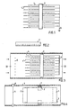
- Fig. 1 shows a filter arrangement with an electrostatic filter according to the invention.
- the other parts in the filter which are known, such as the outer casing, possible fan arrangement, possible control unit etc, are not shown.
- This arrangement is consequently amongst others intended to be mounted in e.g. an electrostatic filter with a fan arrangement which brings the air which is to be cleaned through the filter arrangement.
- the filter can naturally also be placed in a ventilation room where the fan is arranged like a normal extraction fan, i.e. not in connection with the filter.
- the filter comprises two groups of shaped elements which are manufactured from the earlier specified material.
- the elements 1, 1' are arranged in two groups whereby the elements in the two groups are alternatively arranged and groupwise offset with reference to each other.
- the elements 1 in the first group are joined with each other and to earth 3.
- This earthing can for example take place by the elements mounted in the comb-like borders being slid into a holder in the filter casing in the form of a packet until the elements which are to be earthed come into contact with the flexible earth strap of conducting material, for example a porous electrically conducting elastomer or foamed plastic, or a non-rigid textile strip. It should be obvious to the skilled man how such an earthing can be designed in order that the elements to be earthed should make good contact with the earth strip.
- the elements 1, 1' are held at a predetermined distance apart by one or more comb-like borders 2. These comb-like borders are shown seen from the side in Fig. 2.
- the filter arrangement is preferably held together through bands (not shown) tightened around the arrangement. These bands can advantageously be tightened outside the comb-like borders.
- the comb-like borders are made of a insulating material so that the group of elements 1' which are not earthed can continue to take up a potential dependent on the filter arrangement geometry and the charging part. More on this follows below.
- the number of elements is a dimensioning question dependent on the through-flow speed, the size of the through-flow and other parameters which are experimentally determinable by the skilled man.
- Fig. 3 the particle collector part is shown placed in a casing 4 in which in addition to the particle collector part the particle charging part is also arranged, i.e. one or more corona wires 5 are arranged before the arrangement in the flow direction of the air which is shown by arrows.
- corona wires 5 are arranged before the arrangement in the flow direction of the air which is shown by arrows.
- Several electrically conducting, elongated corona wires 5 are wired up in such a way that they run through the casing 4 in its transverse direction and at a distance from the elements.
- the uniting border 2 and the earth-connections 3 between the elements 1 are also shown.
- Fig. 4 shows the same arrangement in a cross section along line IV-IV in Fig. 3.
- Fig. 3 shows the earth-connection which connects the group of plate-like elements 1 to earth and 7 refers to the band which in order to hold the plate-like elements 1, 1' together is tensioned around these and the comb-like means 2.
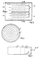
- Fig. 5 shows a second embodiment of a filter arrangement according to the invention placed in a casing 4 in which in addition to the particle collector part a particle charging part is arranged, i.e. a corona electrode 5 is arranged at a predetermined distance in front of the particle collector part in the flow direction of the air which is shown by arrows.
- a particle charging part in addition to the particle collector part a particle charging part is arranged, i.e. a corona electrode 5 is arranged at a predetermined distance in front of the particle collector part in the flow direction of the air which is shown by arrows.
- the particle collector part there are two groups of concentric to each other alternatively arranged hollow cylindrical elements, on one hand earthed elements 1 and on the other hand insulated elements 1'.
- the border 3 earths the group of elements 1.
- Fig. 6 shows the filter arrangement in Fig. 5 in cross section.
- the casing here has also been referenced by reference numeral 4 and the earthed elements with 1 and the insulated elements with 1'.
- distance elements In order to hold the concentric elements at the right distance apart, distance elements (not shown) are used.
- the two groups of earthed respectively unearthed elements are not offset in relationship to each other, they can have essentially the same size or alternatively have different lengths in the direction of flow, i.e. the edges of the elements which are furthest away in the direction of flow could extend equally far while the front edges of the non-earthed elements could extend nearer to the particle charging unit whereby the earthing of the elements which are to be earthed must be arranged in a somewhat different manner.
- the comb-like borders can be placed as necessary either in pairs or alternatively on each side of the plate-like elements. It is also conceivable that in certain special cases it would not be necessary to have more than one comb-like border to hold together the packet. In the case with concentrically arranged elements the comb-like border can if desired be replaced by other forms of electrically non-conducting distance elements.
- the particles which are to be separated out of the air flowing through the electrostatic filter are charged during passage through the high-voltage part, i.e. where they pass the corona wires.
- the group of elements which are not earthed and which extend forwardly past the earthed elements will have an electrical voltage distribution which is dependent on the geometry and voltage on the corona wires.
- the edges of these elements which are placed nearest to the corona wires will have a opposing charge to the corona wires, i.e. the same charge but not necessarily of the same strength which the particles receive during their passage through the particle charging part past the corona wires. This means that the particles will be led to the desired degree in the direction towards the earthed elements whereby a discharging of the particles towards earth occurs and whereby the particles are adsorbed on the surface of the earthed elements.
- the elements with their uniting band can easily be removed from the filter arrangement as a packet and cleaned in an elective manner, for example through simple rinsing, or the arrangement can be recycled.
- Fig. 7 shows a plate-like element 20, 20' intended for a supply air terminal.
- This element comprises three different zones of polymer plastic material with different characteristics.
- the first zone 10 is formed from the material which is described above in connection to the elements 1 respectively l'comprised in the particle collecting unit.
- the second zone 11 is made of an electrically insulating plastic material and the third zone 12 is made from a plastic, a conducting polymer, for example having a PCT (positive temperature coefficient) effect upon the application of a voltage. This means that the electrical resistance of the plastic increases with increasing temperature.
- PCT positive temperature coefficient
- zone 12 two electrical conductors 15, 16 are arranged, for example parallel with the longitudinal direction of the element and which are connectible to an electrical voltage source with example 220 or 110 V alternating current. By connecting a voltage a resistive heating up of the material occurs.
- These extended elements 20, 20' can be made through joint extrusion of the different materials whereby they form a continuous unit.
- the second zone 11 can also be shaped with stamped out openings in order to permit, for example, one or more corona wires to pass through the elements. The reason for this is described below.
- Fig. 8 shows schematically a first embodiment of the supply air terminal comprising an electrostatic filter according to the invention where the extended element according to Fig. 7 is arranged essentially in the same way as described for the electrostatic filter above, but where the regions of the elements which are made of the electrically heatable plastic are arranged in connection to and after the particle collecting unit.
- the outer casing of the outlet is shown by 4.
- the front edge of the element 20' which belongs to the group of electrically insulated elements, partially hidden by an element 20 lying in front of it which belongs to the group of earthed elements.
- These two types are preferably arranged alternatively.
- the part of the elements which are referenced with 10 concerns the zone which has the special mass resistivity which was mentioned earlier for the polymer materials according to the invention, i.e.
- this part of the element essentially consists of one or more non-hygroscopic polymer materials with a mass resistivity which lies within the region 1x10 2 ⁇ cm to 1x10 8 ⁇ cm, more preferably 1x10 3 ⁇ cm to 1x10 7 ⁇ cm, more precisely 1x10 3 ⁇ cm to 1x10 4 ⁇ cm.
- Zone 11 with the non-conducting plastic follows in the direction of flow of the air and then zone 16 with electrical heating by means of conductors 15 and 16 which are connectible according to the above.
- Fig. 9 shows schematically a second embodiment of a supply air terminal comprising the electrostatic filter according to the invention, where the elements according to Fig. 7 are arranged essentially in the same way as described for the electrostatic filter above but where the regions of the elements which are made of the electrically heatable plastic are arranged in direct connection to and in front of the particle collecting unit.
- the particle collector zone wherein the front element 20' belongs to the group of electrically insulated elements and behind this there is a partially hidden element 20 which belongs to the group of earthed elements.
- the part of the elements which have the reference sign 10 concern the zone which has the special mass resistivity which was given above for the polymer material according to the invention, i.e. the part of the elements that essentially consists of one or more non-hygroscopic polymer materials with a mass resistivity which lies within the region of 1x10 2 ⁇ cm to 1x10 8 ⁇ cm, more preferably 1x10 3 ⁇ cm to 1x10 7 ⁇ cm, more precisely 1x10 3 ⁇ cm to 1x10 4 ⁇ cm.
- the embodiment according to Fig. 7 to 9 can also be arranged in the shape of cylindrical elements in the same manner as shown in the embodiment according to Fig. 5 and Fig. 6.
Abstract
Description
- Fig. 1
- shows a plurality of plate-like elements according to the invention with the uniting comb-like means in a view seen from above.
- Fig. 2
- shows the comb-like uniting means from the side.
- Fig. 3
- shows a first embodiment of an electrostatic filter according to the invention placed in a casing or a duct seen in the direction of flow of the flow with the upper side of the casing or duct removed.
- Fig. 4
- shows a section along the line IV-IV in Fig. 3, where,however, the upper side of the duct/casing is shown.
- Fig. 5
- shows a second embodiment of an electrostatic filter according to the invention.
- Fig. 6
- shows a section through the filter in Fig. 5 along the line VI-VI.
- Fig. 7
- shows a plate-like element intended for a supply air terminal which comprises the electrostatic filter according to the invention as an integrated unit.
- Fig. 8
- shows schematically a first embodiment of a supply air terminal comprising the electrostatic filter according to the invention.
- Fig. 9
- shows schematically a second embodiment of a supply air terminal comprising the electrostatic filter according to the invention.
Claims (9)
- Electrostatic filter for the separation of particles which comprises a particle charging unit upstream comprising at least one corona wire for the charging of particles and a particle collector unit arranged relatively downstream to this, which particle collector unit comprises two groups of plate-like elements (1,1') alternately arranged at a predetermined distance from each other and parallel to each other and parallel to the direction of flow through the device, whereby a first group of plate-like elements (1) are connected to earth (3) and a second group of plate-like elements (1') are electrically insulated with reference to the device and the first group of plate-like elements (1) characterized in that the said elements (1,1') essentially consist of one or more non-hygroscopic polymer materials with a mass resistivity which is within the region of 1x10² Ωcm to 1x10⁸ Ωcm, more preferably 1x10³ Ωcm to 1x10⁷ Ωcm, more precisely 1x10³ Ωcm to 1x10⁴ Ωcm.
- Electrostatic filter for the separation of particles which comprises a particle charging unit comprising at least one corona electrode (5) for the charging of particles arranged upstream and a particle collector unit arranged downstream relative to it, which particle collector unit comprises two groups of elements (1,1') alternately arranged at a predetermined distance from each other whereby a first group of elements (1) are connected to earth (3) and a second group of elements (1') are electrically insulated with respect to the device and the first group of elements (1) characterized in that the elements (1,1') are parallel concentric to each other, hollow cylindrical elements (1,1') and that the said elements (1,1') essentially consist of one or more non-hygroscopic polymer materials with a mass resistivity which lies within the region of 1x10² Qcm to 1x10⁸ Ωcm, more preferably 1x10³ Ωcm to 1x10⁷ Ωcm, more precisely 1x10³ Ωcm to 1x10⁴ Ωcm.
- Electrostatic filter according to claim 1 or 2, characterized in that the elements are alternately offset between themselves in the longitudinal direction of the elements, whereby the first group of elements (1) are arranged furthest away from the particle charging part and are connected to earth (3) and that the second group of elements (1') are electrically insulated with respect to the device and to the first group of elements (1) and arranged nearer to the particle charging part.
- Electrostatic filter according to claims 1-3, characterized in that holding-together means (2) of essentially insulating material, preferably with a comb-like shape, are arranged in order to hold the elements (1,1') at a predetermined relative distance from each other.
- Electrostatic filter according to any of the previous claims, characterized in that the round elements (1,1') and the holding-together means (2) use a band in order to form a packet.
- Electrostatic filter according to any of the previous claims, characterized in that the material in the elements (1,1') is a doped plastic material where preferably carbon is used as the doping substance.
- Electrostatic filter according to any of the previous claims, characterized in that the surface of the elements during manufacturing is given a non-smooth, uneven alternatively roughened surface through a mould for manufacturing of the element/elements being equipped with a surface which during pressing, alternatively moulding of the elements on it provides a rough/non-smooth uneven surface.
- Electrostatic filter according to any of the previous claims, characterized in that the elements have at least two zones with different resistivities separated from each other by means of an area with a higher or lower resistivity.
- Supply air terminal, characterized in that it comprises as an integrated unit an electrostatic filter according to any of the claims 1 to 8, further by that at least a predetermined number of the elements (1,1') composed in the filter unit are shaped so as to form a first zone (10) in an enlarged element (20,20') which continuously at the one end goes over into a second zone (11) with electrically insulating plastic and that the second zone (11) continuously goes over into a third zone (12) which comprises a conducting plastic suitable for resistance heating and wherein this zone (12) has at least two conductors (15,16) connectible to a voltage source, arranged for electrical resistant heating of at least a part of the third zone (12).
Applications Claiming Priority (3)
| Application Number | Priority Date | Filing Date | Title |
|---|---|---|---|
| SE9500461A SE515908C2 (en) | 1995-02-08 | 1995-02-08 | Electrostatic filter device |
| SE9500461 | 1995-02-08 | ||
| PCT/SE1996/000151 WO1996024437A1 (en) | 1995-02-08 | 1996-02-08 | Electrostatic filter and supply air terminal |
Publications (2)
| Publication Number | Publication Date |
|---|---|
| EP0809535A1 EP0809535A1 (en) | 1997-12-03 |
| EP0809535B1 true EP0809535B1 (en) | 2002-07-10 |
Family
ID=20397139
Family Applications (1)
| Application Number | Title | Priority Date | Filing Date |
|---|---|---|---|
| EP96902576A Expired - Lifetime EP0809535B1 (en) | 1995-02-08 | 1996-02-08 | Electrostatic filter and supply air terminal |
Country Status (16)
| Country | Link |
|---|---|
| US (2) | US6090189A (en) |
| EP (1) | EP0809535B1 (en) |
| JP (2) | JP4033410B2 (en) |
| KR (1) | KR100419525B1 (en) |
| CN (1) | CN1113700C (en) |
| AT (1) | ATE220350T1 (en) |
| AU (1) | AU705254B2 (en) |
| BR (1) | BR9607525A (en) |
| CA (1) | CA2212408C (en) |
| DE (1) | DE69622257T2 (en) |
| FI (1) | FI121701B (en) |
| MX (1) | MX9706087A (en) |
| NO (1) | NO317489B1 (en) |
| RU (1) | RU2156662C2 (en) |
| SE (1) | SE515908C2 (en) |
| WO (1) | WO1996024437A1 (en) |
Cited By (1)
| Publication number | Priority date | Publication date | Assignee | Title |
|---|---|---|---|---|
| WO2017149193A1 (en) * | 2016-03-04 | 2017-09-08 | Aavi Technologies Ltd | Air purifier |
Families Citing this family (48)
| Publication number | Priority date | Publication date | Assignee | Title |
|---|---|---|---|---|
| SE515908C2 (en) * | 1995-02-08 | 2001-10-29 | Purocell Sa | Electrostatic filter device |
| US7695690B2 (en) | 1998-11-05 | 2010-04-13 | Tessera, Inc. | Air treatment apparatus having multiple downstream electrodes |
| US20030206837A1 (en) | 1998-11-05 | 2003-11-06 | Taylor Charles E. | Electro-kinetic air transporter and conditioner device with enhanced maintenance features and enhanced anti-microorganism capability |
| GB9908099D0 (en) * | 1999-04-12 | 1999-06-02 | Gay Geoffrey N W | Air cleaning collection device |
| JP3287468B2 (en) * | 1999-11-15 | 2002-06-04 | 株式会社オーデン | Electric dust collection unit |
| CA2317830C (en) * | 2000-09-08 | 2009-10-20 | Her Majesty The Queen In Right Of Canada As Represented By The Minister Of The Environment | Particle concentrator |
| SE519468C2 (en) * | 2001-08-10 | 2003-03-04 | Andrzej Loreth | particle separator |
| JP2003144970A (en) * | 2001-11-16 | 2003-05-20 | Fuji Photo Film Co Ltd | Dust collection equipment |
| AU2003239493A1 (en) * | 2002-05-15 | 2003-12-02 | University Of Kentucky Research Foundation | Particle separation/purification system, diffuser and related methods |
| DE10232602A1 (en) * | 2002-07-18 | 2004-02-05 | Mann + Hummel Gmbh | Device for separating aerosols or particles from gases |
| WO2004067149A1 (en) * | 2003-01-31 | 2004-08-12 | Cft Gmbh Compact Filter Technic | Dust filter for using in operations endangered by gases |
| TWI220654B (en) * | 2003-07-02 | 2004-09-01 | Ind Tech Res Inst | Adjustable whirlpool electrostatic filter |
| US7077890B2 (en) * | 2003-09-05 | 2006-07-18 | Sharper Image Corporation | Electrostatic precipitators with insulated driver electrodes |
| US7906080B1 (en) | 2003-09-05 | 2011-03-15 | Sharper Image Acquisition Llc | Air treatment apparatus having a liquid holder and a bipolar ionization device |
| US7724492B2 (en) | 2003-09-05 | 2010-05-25 | Tessera, Inc. | Emitter electrode having a strip shape |
| SE0302691D0 (en) * | 2003-10-13 | 2003-10-13 | Andrzej Loreth | hybrid Particle |
| US7112236B2 (en) * | 2004-04-08 | 2006-09-26 | Fleetguard, Inc. | Multistage space-efficient electrostatic collector |
| US20060005703A1 (en) * | 2004-06-30 | 2006-01-12 | Chi-Hsiang Wang | Ultraviolet air purifier having multiple charged collection plates |
| WO2006137966A1 (en) * | 2005-06-16 | 2006-12-28 | Washington Savannah River Company, Llc | High volume, multiple use, portable precipitator |
| US7651553B2 (en) * | 2005-09-29 | 2010-01-26 | Sarnoff Corporation | Ballast circuit for electrostatic particle collection systems |
| ES2535312T3 (en) * | 2005-12-29 | 2015-05-08 | Environmental Management Confederation Inc. | Enhanced filter medium for active field polarized medium air purifier |
| US7833322B2 (en) | 2006-02-28 | 2010-11-16 | Sharper Image Acquisition Llc | Air treatment apparatus having a voltage control device responsive to current sensing |
| EP1829614A1 (en) * | 2006-03-02 | 2007-09-05 | Technische Universiteit Delft | Method for the removal of smut, fine dust and exhaust gas particles, particle catch arrangement for use in this method and use of the particle catch arrangement to generate a static electric field |
| JP2008018426A (en) * | 2006-06-15 | 2008-01-31 | Daikin Ind Ltd | Dust collector |
| KR101082713B1 (en) * | 2006-06-15 | 2011-11-15 | 다이킨 고교 가부시키가이샤 | Dust collector |
| EP1878506B1 (en) * | 2006-07-13 | 2019-10-16 | Trinc.Org | Flotage trapping device |
| EP2046500A2 (en) | 2006-07-19 | 2009-04-15 | Koninklijke Philips Electronics N.V. | Electrostatic particle filter |
| JP2008023444A (en) * | 2006-07-20 | 2008-02-07 | Daikin Ind Ltd | Dust collector |
| US20080178737A1 (en) * | 2007-01-31 | 2008-07-31 | Pratt & Whitney Canada Corp. | Woven electrostatic oil precipitator element |
| US20100037776A1 (en) * | 2008-08-14 | 2010-02-18 | Sik Leung Chan | Devices for removing particles from a gas comprising an electrostatic precipitator |
| CN102186594B (en) * | 2008-10-20 | 2015-11-25 | 开利公司 | After adopting, the electricity of fiber charging strengthens air filtering system |
| DE102008055732A1 (en) * | 2008-11-04 | 2010-05-06 | Brandenburgische Technische Universität Cottbus | Process for the electrical separation of aerosols and apparatus for carrying out the process |
| KR101206572B1 (en) * | 2008-11-14 | 2012-11-30 | 다이킨 고교 가부시키가이샤 | Dust collecting device |
| NL2002435C2 (en) * | 2009-01-21 | 2010-07-22 | Stichting Dienst Landbouwkundi | Air mixing system for a broiler house. |
| KR101655452B1 (en) * | 2010-01-29 | 2016-09-08 | 삼성전자주식회사 | Electric precipitator and electrode plate thereof |
| DE102010050543A1 (en) * | 2010-11-16 | 2012-05-16 | Peter Oertmann | Three dimensional device for cleaning toner residue particles at e.g. exhauster for ventilating interior of printer, has lines producing electrostatic field around plates by voltage, where surfaces of plates are roughened |
| KR101827832B1 (en) | 2010-12-24 | 2018-02-12 | 삼성전자주식회사 | Electric precipitator |
| KR101858940B1 (en) * | 2011-06-10 | 2018-05-17 | 삼성전자주식회사 | Electrostatic precipitator |
| CN104028383B (en) * | 2014-06-18 | 2016-06-08 | 上海龙净环保科技工程有限公司 | A kind of wet electrical dust precipitator and using method thereof |
| CN104174493A (en) * | 2014-07-23 | 2014-12-03 | 上海利人净化机械有限公司 | Electronic type dust collector |
| KR101641296B1 (en) * | 2014-10-14 | 2016-07-21 | 한국기계연구원 | Vehicle air purifying apparatus for simultaneously reducing harmful Gas and particles |
| CN105665135B (en) * | 2014-11-18 | 2019-01-08 | 华为技术有限公司 | Dust-extraction unit |
| PE20151196Z (en) * | 2015-03-04 | 2015-08-28 | Prevoo Christian Paul Henriquez | CONCENTRIC ELECTROSTATIC FILTER |
| US10464074B2 (en) | 2015-10-30 | 2019-11-05 | Lg Electronics Inc. | Electric dust collector and air conditioner including the same |
| KR101839557B1 (en) * | 2015-10-30 | 2018-04-26 | 엘지전자 주식회사 | Electric Dust Collection Device and Air Conditioner comprising the same |
| CN105890437B (en) * | 2016-04-07 | 2018-07-17 | 西安交通大学 | A kind of plural parallel stage is multi-thread-moisture film electrode ion Cooling Tower water recovery device |
| JP6979306B2 (en) * | 2017-08-29 | 2021-12-08 | アマノ株式会社 | Electrostatic precipitator and range hood with built-in electrostatic precipitator |
| SE542576C2 (en) * | 2018-04-18 | 2020-06-09 | Eurus Airtech Ab | Highly resistive electrode elements for two-stage electrofilter |
Family Cites Families (22)
| Publication number | Priority date | Publication date | Assignee | Title |
|---|---|---|---|---|
| US2181767A (en) * | 1938-05-06 | 1939-11-28 | Westinghouse Electric & Mfg Co | Electrostatic precipitator |
| US2875845A (en) * | 1955-03-18 | 1959-03-03 | Gaylord W Penney | Electrostatic precipitator |
| US2989144A (en) * | 1956-01-02 | 1961-06-20 | Styrie Otto | Method of and apparatus for purifying and decontaminating exhaust gases of combustion devices |
| US2926749A (en) * | 1956-01-27 | 1960-03-01 | Messen Jaschin G A | Separator-electrodesystem for electrofilters |
| US2873000A (en) * | 1956-05-08 | 1959-02-10 | Lowell S Elam | Electrostatic precipitator |
| US3487610A (en) * | 1965-03-26 | 1970-01-06 | Du Pont | Electrostatic filter unit with high stable charge and its manufacture |
| US3782905A (en) * | 1972-05-01 | 1974-01-01 | A Huang | Electrostatic precipitating apparatus and method |
| US4072477A (en) * | 1972-05-11 | 1978-02-07 | The Regents Of The University Of California | Electrostatic precipitation process |
| ZA744247B (en) * | 1973-08-31 | 1975-06-25 | Metallgesellschaft Ag | Electrostatic precipitator made of plastics material |
| JPS5369980A (en) | 1976-12-02 | 1978-06-21 | Fuji Electric Co Ltd | Electric dust collector |
| JPS56168255U (en) * | 1980-05-14 | 1981-12-12 | ||
| JPS5820251A (en) * | 1981-07-31 | 1983-02-05 | ジヤツク・ケネス・イボツト | Electrostatic air cleaner |
| DE3418577A1 (en) * | 1984-05-18 | 1985-11-21 | Masuda, Senichi, Tokio/Tokyo | FILM SHAPED DUST COLLECTING ELECTRODES AND ELECTRIC DUST COLLECTING DEVICE WITH A STACK OF SUCH DUST COLLECTING ELECTRODES |
| JPS61164664A (en) * | 1985-01-17 | 1986-07-25 | Matsushita Electric Ind Co Ltd | Ion wind electrostatic type air purifier |
| US4861356A (en) * | 1985-05-17 | 1989-08-29 | Penney Gaylord W | Close-spaced electrostatic precipitator |
| JPS62144768A (en) * | 1985-12-18 | 1987-06-27 | Mitsubishi Heavy Ind Ltd | Electric precipitator |
| JP2628528B2 (en) * | 1988-01-08 | 1997-07-09 | 株式会社ダスキン | Dust concentration detection device and air purifier equipped therewith |
| JP2627575B2 (en) * | 1990-08-15 | 1997-07-09 | 高砂熱学工業株式会社 | Method for preventing sea salt particle contamination in clean room for semiconductor manufacturing |
| SE469466B (en) | 1992-02-20 | 1993-07-12 | Tl Vent Ab | DOUBLE STEP ELECTROFILTER |
| JPH078836A (en) * | 1993-06-21 | 1995-01-13 | Daikin Ind Ltd | Dust collecting electrode plate for electric precipitation element |
| SE9303059D0 (en) * | 1993-09-17 | 1993-09-17 | Purocell Sa | Apparatus for an electrostatic filter and an apparatus comprising at least one such apparatus |
| SE515908C2 (en) * | 1995-02-08 | 2001-10-29 | Purocell Sa | Electrostatic filter device |
-
1995
- 1995-02-08 SE SE9500461A patent/SE515908C2/en not_active IP Right Cessation
-
1996
- 1996-02-08 US US08/875,946 patent/US6090189A/en not_active Expired - Lifetime
- 1996-02-08 KR KR1019970705464A patent/KR100419525B1/en not_active IP Right Cessation
- 1996-02-08 RU RU97114740/12A patent/RU2156662C2/en not_active IP Right Cessation
- 1996-02-08 AT AT96902576T patent/ATE220350T1/en not_active IP Right Cessation
- 1996-02-08 MX MX9706087A patent/MX9706087A/en unknown
- 1996-02-08 JP JP52420496A patent/JP4033410B2/en not_active Expired - Fee Related
- 1996-02-08 CA CA002212408A patent/CA2212408C/en not_active Expired - Fee Related
- 1996-02-08 CN CN96191863A patent/CN1113700C/en not_active Expired - Fee Related
- 1996-02-08 EP EP96902576A patent/EP0809535B1/en not_active Expired - Lifetime
- 1996-02-08 DE DE69622257T patent/DE69622257T2/en not_active Expired - Lifetime
- 1996-02-08 WO PCT/SE1996/000151 patent/WO1996024437A1/en active IP Right Grant
- 1996-02-08 BR BR9607525A patent/BR9607525A/en not_active IP Right Cessation
- 1996-02-08 AU AU46837/96A patent/AU705254B2/en not_active Ceased
-
1997
- 1997-08-07 FI FI973264A patent/FI121701B/en not_active IP Right Cessation
- 1997-08-07 NO NO19973645A patent/NO317489B1/en not_active IP Right Cessation
-
2000
- 2000-06-23 US US09/599,389 patent/US6241810B1/en not_active Expired - Lifetime
-
2007
- 2007-07-05 JP JP2007177315A patent/JP4519158B2/en not_active Expired - Fee Related
Cited By (1)
| Publication number | Priority date | Publication date | Assignee | Title |
|---|---|---|---|---|
| WO2017149193A1 (en) * | 2016-03-04 | 2017-09-08 | Aavi Technologies Ltd | Air purifier |
Also Published As
| Publication number | Publication date |
|---|---|
| CN1113700C (en) | 2003-07-09 |
| JP2007326102A (en) | 2007-12-20 |
| SE515908C2 (en) | 2001-10-29 |
| DE69622257T2 (en) | 2003-03-06 |
| JPH10513118A (en) | 1998-12-15 |
| KR19980702069A (en) | 1998-07-15 |
| FI973264A (en) | 1997-10-07 |
| ATE220350T1 (en) | 2002-07-15 |
| WO1996024437A1 (en) | 1996-08-15 |
| BR9607525A (en) | 1997-12-30 |
| JP4033410B2 (en) | 2008-01-16 |
| AU4683796A (en) | 1996-08-27 |
| FI973264A0 (en) | 1997-08-07 |
| CA2212408A1 (en) | 1996-08-15 |
| CA2212408C (en) | 2006-11-14 |
| JP4519158B2 (en) | 2010-08-04 |
| DE69622257D1 (en) | 2002-08-14 |
| NO973645D0 (en) | 1997-08-07 |
| FI121701B (en) | 2011-03-15 |
| SE9500461L (en) | 1996-08-09 |
| RU2156662C2 (en) | 2000-09-27 |
| US6241810B1 (en) | 2001-06-05 |
| SE9500461D0 (en) | 1995-02-08 |
| NO973645L (en) | 1997-09-30 |
| EP0809535A1 (en) | 1997-12-03 |
| AU705254B2 (en) | 1999-05-20 |
| NO317489B1 (en) | 2004-11-08 |
| KR100419525B1 (en) | 2004-04-21 |
| US6090189A (en) | 2000-07-18 |
| CN1173833A (en) | 1998-02-18 |
| MX9706087A (en) | 1998-02-28 |
Similar Documents
| Publication | Publication Date | Title |
|---|---|---|
| EP0809535B1 (en) | Electrostatic filter and supply air terminal | |
| MXPA97006087A (en) | Electrostatic filter and air terminal of suminis | |
| EP1169131B1 (en) | Air cleaning device | |
| RU97114740A (en) | ELECTROSTATIC FILTER AND AIR SUPPLY TERMINAL | |
| CA2190954C (en) | Electrostatic fibrous filter | |
| US6454839B1 (en) | Electrofiltration apparatus | |
| JP2905036B2 (en) | Electrostatic particle filtration device | |
| JP2002540935A5 (en) | ||
| US2502560A (en) | Electrical gas cleaner unit | |
| JPH0622443Y2 (en) | Air purifier dust collector | |
| US2908347A (en) | Electrostatic precipitators | |
| CN204583471U (en) | Electrostatic precipitator | |
| JPH08227789A (en) | Resin electrode | |
| WO1995007759A1 (en) | Device for an electrostatic filter, and installation comprising at least one such device | |
| JPH02280852A (en) | Electrical dust precipitator | |
| CA2138118A1 (en) | Device for removing dust particles from exhaust gases | |
| RU13619U1 (en) | ELECTRIC FILTER | |
| JPH0236611Y2 (en) | ||
| EP2052782A1 (en) | Dust collecting apparatus |
Legal Events
| Date | Code | Title | Description |
|---|---|---|---|
| PUAI | Public reference made under article 153(3) epc to a published international application that has entered the european phase |
Free format text: ORIGINAL CODE: 0009012 |
|
| 17P | Request for examination filed |
Effective date: 19970806 |
|
| AK | Designated contracting states |
Kind code of ref document: A1 Designated state(s): AT BE CH DE DK ES FR GB GR IE IT LI NL PT SE |
|
| 17Q | First examination report despatched |
Effective date: 20000303 |
|
| GRAG | Despatch of communication of intention to grant |
Free format text: ORIGINAL CODE: EPIDOS AGRA |
|
| GRAG | Despatch of communication of intention to grant |
Free format text: ORIGINAL CODE: EPIDOS AGRA |
|
| GRAH | Despatch of communication of intention to grant a patent |
Free format text: ORIGINAL CODE: EPIDOS IGRA |
|
| GRAH | Despatch of communication of intention to grant a patent |
Free format text: ORIGINAL CODE: EPIDOS IGRA |
|
| GRAH | Despatch of communication of intention to grant a patent |
Free format text: ORIGINAL CODE: EPIDOS IGRA |
|
| GRAA | (expected) grant |
Free format text: ORIGINAL CODE: 0009210 |
|
| AK | Designated contracting states |
Kind code of ref document: B1 Designated state(s): AT BE CH DE DK ES FR GB GR IE IT LI NL PT SE |
|
| PG25 | Lapsed in a contracting state [announced via postgrant information from national office to epo] |
Ref country code: GR Free format text: LAPSE BECAUSE OF FAILURE TO SUBMIT A TRANSLATION OF THE DESCRIPTION OR TO PAY THE FEE WITHIN THE PRESCRIBED TIME-LIMIT Effective date: 20020710 Ref country code: BE Free format text: LAPSE BECAUSE OF FAILURE TO SUBMIT A TRANSLATION OF THE DESCRIPTION OR TO PAY THE FEE WITHIN THE PRESCRIBED TIME-LIMIT Effective date: 20020710 Ref country code: AT Free format text: LAPSE BECAUSE OF FAILURE TO SUBMIT A TRANSLATION OF THE DESCRIPTION OR TO PAY THE FEE WITHIN THE PRESCRIBED TIME-LIMIT Effective date: 20020710 |
|
| REF | Corresponds to: |
Ref document number: 220350 Country of ref document: AT Date of ref document: 20020715 Kind code of ref document: T |
|
| REG | Reference to a national code |
Ref country code: GB Ref legal event code: FG4D |
|
| REG | Reference to a national code |
Ref country code: CH Ref legal event code: EP |
|
| REG | Reference to a national code |
Ref country code: IE Ref legal event code: FG4D |
|
| REF | Corresponds to: |
Ref document number: 69622257 Country of ref document: DE Date of ref document: 20020814 |
|
| PG25 | Lapsed in a contracting state [announced via postgrant information from national office to epo] |
Ref country code: SE Free format text: LAPSE BECAUSE OF FAILURE TO SUBMIT A TRANSLATION OF THE DESCRIPTION OR TO PAY THE FEE WITHIN THE PRESCRIBED TIME-LIMIT Effective date: 20021010 Ref country code: PT Free format text: LAPSE BECAUSE OF FAILURE TO SUBMIT A TRANSLATION OF THE DESCRIPTION OR TO PAY THE FEE WITHIN THE PRESCRIBED TIME-LIMIT Effective date: 20021010 Ref country code: DK Free format text: LAPSE BECAUSE OF FAILURE TO SUBMIT A TRANSLATION OF THE DESCRIPTION OR TO PAY THE FEE WITHIN THE PRESCRIBED TIME-LIMIT Effective date: 20021010 |
|
| REG | Reference to a national code |
Ref country code: CH Ref legal event code: NV Representative=s name: BOVARD AG PATENTANWAELTE |
|
| ET | Fr: translation filed | ||
| PG25 | Lapsed in a contracting state [announced via postgrant information from national office to epo] |
Ref country code: ES Free format text: LAPSE BECAUSE OF FAILURE TO SUBMIT A TRANSLATION OF THE DESCRIPTION OR TO PAY THE FEE WITHIN THE PRESCRIBED TIME-LIMIT Effective date: 20030130 |
|
| PG25 | Lapsed in a contracting state [announced via postgrant information from national office to epo] |
Ref country code: IE Free format text: LAPSE BECAUSE OF NON-PAYMENT OF DUE FEES Effective date: 20030210 |
|
| PLBE | No opposition filed within time limit |
Free format text: ORIGINAL CODE: 0009261 |
|
| STAA | Information on the status of an ep patent application or granted ep patent |
Free format text: STATUS: NO OPPOSITION FILED WITHIN TIME LIMIT |
|
| RAP2 | Party data changed (patent owner data changed or rights of a patent transferred) |
Owner name: PUROCELL HOLDING S.A. |
|
| 26N | No opposition filed |
Effective date: 20030411 |
|
| NLT2 | Nl: modifications (of names), taken from the european patent patent bulletin |
Owner name: PUROCELL HOLDING S.A. |
|
| REG | Reference to a national code |
Ref country code: CH Ref legal event code: PFA Owner name: PUROCELL HOLDING S.A. Free format text: PUROCELL S.A.#LE HAMEAU#1936 VERBIER (CH) -TRANSFER TO- PUROCELL HOLDING S.A.#LE HAMEAU#1936 VERBIER (CH) |
|
| REG | Reference to a national code |
Ref country code: IE Ref legal event code: MM4A |
|
| REG | Reference to a national code |
Ref country code: CH Ref legal event code: PFA Owner name: PUROCELL HOLDING S.A. Free format text: PUROCELL HOLDING S.A.#LE HAMEAU#1936 VERBIER (CH) -TRANSFER TO- PUROCELL HOLDING S.A.#LE HAMEAU#1936 VERBIER (CH) |
|
| PGFP | Annual fee paid to national office [announced via postgrant information from national office to epo] |
Ref country code: DE Payment date: 20140220 Year of fee payment: 19 Ref country code: NL Payment date: 20140228 Year of fee payment: 19 Ref country code: CH Payment date: 20140228 Year of fee payment: 19 |
|
| PGFP | Annual fee paid to national office [announced via postgrant information from national office to epo] |
Ref country code: IT Payment date: 20140228 Year of fee payment: 19 Ref country code: FR Payment date: 20140228 Year of fee payment: 19 |
|
| PGFP | Annual fee paid to national office [announced via postgrant information from national office to epo] |
Ref country code: GB Payment date: 20140220 Year of fee payment: 19 |
|
| REG | Reference to a national code |
Ref country code: DE Ref legal event code: R119 Ref document number: 69622257 Country of ref document: DE |
|
| REG | Reference to a national code |
Ref country code: NL Ref legal event code: V1 Effective date: 20150901 |
|
| PG25 | Lapsed in a contracting state [announced via postgrant information from national office to epo] |
Ref country code: NL Free format text: LAPSE BECAUSE OF NON-PAYMENT OF DUE FEES Effective date: 20150901 |
|
| REG | Reference to a national code |
Ref country code: CH Ref legal event code: PL |
|
| GBPC | Gb: european patent ceased through non-payment of renewal fee |
Effective date: 20150208 |
|
| PG25 | Lapsed in a contracting state [announced via postgrant information from national office to epo] |
Ref country code: CH Free format text: LAPSE BECAUSE OF NON-PAYMENT OF DUE FEES Effective date: 20150228 Ref country code: LI Free format text: LAPSE BECAUSE OF NON-PAYMENT OF DUE FEES Effective date: 20150228 |
|
| REG | Reference to a national code |
Ref country code: FR Ref legal event code: ST Effective date: 20151030 |
|
| PG25 | Lapsed in a contracting state [announced via postgrant information from national office to epo] |
Ref country code: IT Free format text: LAPSE BECAUSE OF NON-PAYMENT OF DUE FEES Effective date: 20150208 |
|
| PG25 | Lapsed in a contracting state [announced via postgrant information from national office to epo] |
Ref country code: DE Free format text: LAPSE BECAUSE OF NON-PAYMENT OF DUE FEES Effective date: 20150901 Ref country code: GB Free format text: LAPSE BECAUSE OF NON-PAYMENT OF DUE FEES Effective date: 20150208 |
|
| PG25 | Lapsed in a contracting state [announced via postgrant information from national office to epo] |
Ref country code: FR Free format text: LAPSE BECAUSE OF NON-PAYMENT OF DUE FEES Effective date: 20150302 |