EP0808519B1 - Sensor connector - Google Patents
Sensor connector Download PDFInfo
- Publication number
- EP0808519B1 EP0808519B1 EP96901089A EP96901089A EP0808519B1 EP 0808519 B1 EP0808519 B1 EP 0808519B1 EP 96901089 A EP96901089 A EP 96901089A EP 96901089 A EP96901089 A EP 96901089A EP 0808519 B1 EP0808519 B1 EP 0808519B1
- Authority
- EP
- European Patent Office
- Prior art keywords
- connector
- cable
- sensor
- outer housing
- shield member
- Prior art date
- Legal status (The legal status is an assumption and is not a legal conclusion. Google has not performed a legal analysis and makes no representation as to the accuracy of the status listed.)
- Expired - Lifetime
Links
- 239000003990 capacitor Substances 0.000 claims abstract description 16
- 230000035939 shock Effects 0.000 claims abstract description 14
- 238000009413 insulation Methods 0.000 claims description 6
- 239000002184 metal Substances 0.000 claims description 6
- 230000007704 transition Effects 0.000 claims description 6
- 239000000463 material Substances 0.000 claims description 5
- 238000006073 displacement reaction Methods 0.000 claims description 3
- 239000012530 fluid Substances 0.000 claims description 3
- 238000002347 injection Methods 0.000 claims description 3
- 239000007924 injection Substances 0.000 claims description 3
- 238000000465 moulding Methods 0.000 claims description 3
- 230000014759 maintenance of location Effects 0.000 claims description 2
- 238000007789 sealing Methods 0.000 claims description 2
- 230000013011 mating Effects 0.000 claims 1
- 238000005476 soldering Methods 0.000 abstract description 8
- 238000001914 filtration Methods 0.000 abstract description 3
- 238000002485 combustion reaction Methods 0.000 description 10
- 239000004020 conductor Substances 0.000 description 4
- 238000005452 bending Methods 0.000 description 2
- 239000000243 solution Substances 0.000 description 2
- 230000005540 biological transmission Effects 0.000 description 1
- 230000008602 contraction Effects 0.000 description 1
- 230000008878 coupling Effects 0.000 description 1
- 238000010168 coupling process Methods 0.000 description 1
- 238000005859 coupling reaction Methods 0.000 description 1
- 238000002788 crimping Methods 0.000 description 1
- 239000013536 elastomeric material Substances 0.000 description 1
- 239000000446 fuel Substances 0.000 description 1
- 239000007788 liquid Substances 0.000 description 1
- 239000011344 liquid material Substances 0.000 description 1
- 230000008054 signal transmission Effects 0.000 description 1
- 229920002379 silicone rubber Polymers 0.000 description 1
- 229910000679 solder Inorganic materials 0.000 description 1
- 239000000758 substrate Substances 0.000 description 1
Images


Classifications
-
- H—ELECTRICITY
- H01—ELECTRIC ELEMENTS
- H01R—ELECTRICALLY-CONDUCTIVE CONNECTIONS; STRUCTURAL ASSOCIATIONS OF A PLURALITY OF MUTUALLY-INSULATED ELECTRICAL CONNECTING ELEMENTS; COUPLING DEVICES; CURRENT COLLECTORS
- H01R13/00—Details of coupling devices of the kinds covered by groups H01R12/70 or H01R24/00 - H01R33/00
- H01R13/66—Structural association with built-in electrical component
- H01R13/6608—Structural association with built-in electrical component with built-in single component
- H01R13/6625—Structural association with built-in electrical component with built-in single component with capacitive component
-
- H—ELECTRICITY
- H01—ELECTRIC ELEMENTS
- H01R—ELECTRICALLY-CONDUCTIVE CONNECTIONS; STRUCTURAL ASSOCIATIONS OF A PLURALITY OF MUTUALLY-INSULATED ELECTRICAL CONNECTING ELEMENTS; COUPLING DEVICES; CURRENT COLLECTORS
- H01R13/00—Details of coupling devices of the kinds covered by groups H01R12/70 or H01R24/00 - H01R33/00
- H01R13/58—Means for relieving strain on wire connection, e.g. cord grip, for avoiding loosening of connections between wires and terminals within a coupling device terminating a cable
- H01R13/5845—Means for relieving strain on wire connection, e.g. cord grip, for avoiding loosening of connections between wires and terminals within a coupling device terminating a cable the strain relief being achieved by molding parts around cable and connections
-
- H—ELECTRICITY
- H01—ELECTRIC ELEMENTS
- H01R—ELECTRICALLY-CONDUCTIVE CONNECTIONS; STRUCTURAL ASSOCIATIONS OF A PLURALITY OF MUTUALLY-INSULATED ELECTRICAL CONNECTING ELEMENTS; COUPLING DEVICES; CURRENT COLLECTORS
- H01R13/00—Details of coupling devices of the kinds covered by groups H01R12/70 or H01R24/00 - H01R33/00
- H01R13/66—Structural association with built-in electrical component
- H01R13/719—Structural association with built-in electrical component specially adapted for high frequency, e.g. with filters
Definitions
- This invention relates to an electrical connector for coupling to a sensor, for example a sensor mounted in a combustion chamber, the connector being resistant to shock and electrostatic and electromagnetic interference.
- pressure sensors have been developed for positioning in combustion chambers of combustion engines to determine the combustion characteristics (pressure over time) of the ignited fuel within the piston chamber.
- Such sensors might comprise a piezo electrical device for measuring the pressure variations, or other electrically driven pressure sensors, which thus need to be supplied with leads for electrical power and signal transmission.
- the signal leads need to be protected from this interference by shielding and possibly filtering.
- a further problem are the high shocks generated by the combustion.
- the connector must be able to withstand the shocks over the specified life of the combustion engine whilst making reliable connection with the sensor.
- Other sensors for use in an automobile or other types of vehicles may of course also be subject to mechanical shock, thermal solicitation, and electromagnetic noise.
- the connector includes an insulating body in which at least one contact is arranged.
- the connector further includes a shield member which has apertures for terminals which project through the shield member.
- the shield member may also be the ground contact element which is arranged on or in the insulating body.
- a filter arrangement may be arranged between the contact and the ground contact element.
- the connector substantially comprises an outer housing having a cavity extending therethrough, and a connection section mounted therein that has an insulative housing and terminals for connection to leads of a sensor cable, further comprising a conductive shield member mounted transversely to the passage of the cavity and extending substantially fully thereacross except for around the terminals which project past the shield member.
- the shield member could be a stamped and formed plate that is overmoulded by the housing, or securely fixed thereto.
- the inner housing may be fully received within the outer housing, the inner housing comprising cavities for receiving receptacle contact portions of the terminals for electrical contact with pin contacts of the sensor.
- the contact portions may be integral with an insulation displacement contact (IDC) connection portion for contacting the sensor leads, the housing having a plurality of slots extending substantially parallel to each other from an outer surface of the housing to the IDC connection sections to allow stuffing of the leads into the IDC sections therethrough.
- IDC insulation displacement contact
- the terminals could further comprise additional contact legs extending therefrom for electrical contact to a pole of a capacitor or another filter element, the other pole of the filter element electrically connected to the shield member.
- the shield member could be formed by conductive material covering a printed circuit board, the board also having circuit traces for interconnecting the terminals to the filter elements which could, for example, be surface mounted to the printed circuit board.
- a stamped and formed metal clip having spring arms could be mounted to the printed circuit board for electrical contact with the outer housing (which is electrically connected to ground).
- the outer housing would thus be an electrical conductor, for example a metal, which is electrically connected to conductive shielding of the cable at a cable receiving end.
- Such cable may have a drain wire, which could be electrically connected to the outer housing by overmoulding an end portion of the cable beyond which the leads extend with a conductive material, for example a conductive plastic material that is easy to mould.
- the outer housing could be provided to extend along a certain length of the cable and the space therebetween injected with a plastic or elastomeric material to securely attach the cable to the outer housing to provide sufficient strain relief for axial and bending forces on the wire.
- Resistance to shock could be enhanced by tight abutment of the inner housing against the cable end overmouldings, and soldering of the filter elements to the shielding and the terminals.
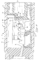
- a sensor connector 2 comprises an outer housing 4 having a cavity 6 extending therethrough from a cable receiving end 8 to a sensor receiving end 10, and a connection section 12 positioned within the outer housing 4.
- the connection section 12 extends from the sensor end 10 to an intermediate position within the cavity 6.
- a sensor cable 14 extends into the cavity 6 through the cable receiving end 8 to its end 16 proximate the connection section 12, where leads 18 of the cable 14 then continue into the connection section 12 for electrical connection therewith.
- the cable 14 has an outer insulative layer surrounding a conductive shielding that surrounds the plurality of leads 18 (in this case 3).
- a drain wire 20 is provided, and in this case folded back over the outside of the cable 14 from the end 16.
- a section of the cavity 6 from a cable end 24 of the connection section 12 to a position beyond the drain wire 20 is injection moulded with a conductive plastic material 26 that electrically interconnects the drain wire 20 (and therefore the cable shielding) to the outer housing which in this embodiment is made of metal and thus acts as shielding around the connector.
- the cable end overmoulding 26 also acts as a strain relief member to securely retain the cable to the outer housing.
- the outer housing 4 is connected to ground via a casing around the sensor which is connected for example to the engine block of the combustion chamber.
- Extending from a rear end 28 of the conductive moulded section 26 is an elastomeric or other flexible tubular member 34 filling the space between the cable and the outer housing rear end that extends over a certain length of the cable.
- the surface of the tubular member 34 is provided with circumferential ribs 32 to seal against the housing 4.
- the tubular member 34 extends beyond the cable receiving end 8 out of the housing cavity 6 in order to stiffen and protect the cable from overbending which is most critical at the outlet of the housing 4. It would of course also be conceivable to provide the tubular member 34 in the same material as the grounding section 26 to simplify the moulding thereof, where the ribs 32 would enhance the electrical contact against the outer housing.
- the connection section 12 comprises an insulative housing 36, a plurality of terminals 38 mounted in the housing 36, and a shield member 40.
- the housing 36 comprises a sensor receiving section 37 and a cable receiving section 39 on either side of the shield member 40.
- the insulative housing 36 comprises a plurality of receptacle contact receiving cavities 42 extending therein from the sensor end 10, and further sensor contact receiving cavities 44 also extending from the sensor end 10 therein, the cavities 42,44 disposed circumferentially around a central portion 46 of the housing 36.
- a connection end 48 of a sensor is shown comprising a plurality of pin contacts 50 disposed circumferentially around, proximate the outer surface 52 of the sensor.
- the terminals 38 comprise a receptacle contact section 54 received within the housing cavities 42, attached to a lead connection section 56 via a transition strip 58.
- the terminal 38 is stamped and formed from sheet metal.
- the lead connection section 56 comprises insulation displacement contacts for connection to electrical strands of the leads by cutting through the lead outer insulation and contacting the inner strands.
- the insulation displacing contact (IDC) 57 thus cuts through the outer insulation when the lead 18 is stuffed in the direction of arrow S into the IDC contacts.
- Other known connection means such as crimping or soldering could of course be considered, however IDC connection provides a rapid and cost-effective solution.
- Each receptacle contact 54 comprises a cylindrical base portion 59 which extends into two pairs of opposed contact arms 55 forming a pin receiving cavity to receive and contact the pin contacts 50 with four points of contact.
- the receptacle contact extends into the transition strip 58 proximate and along the outer housing 10 as it extends past the shield member 40 to allow the shield element to extend as far as possible across the cavity 6 for reasons that will be understood herebelow.
- the transition strip 58 is bent at a right angle and can thus act as a flexible member in the longitudinal direction of the outer housing for compensation thermal expansion/contraction of the various components to which the terminals are attached.
- the cable receiving section 39 of the housing 36 comprises slots extending from one side 43, the slots 41 each for receiving a connection section of the terminals 38 to allow passage of the wire therethrough for connection to the terminal.
- a base wall 45 of the slots 41 provides a seat for positioning of the terminal connection section thereagainst. Due to the transverse positioning of the shield member 40 across most of the cavity 6, the housing 36 comprises a slot 47 separating the sensor section 37 from the cable section 39 such that these two sections are connected together by a thin arc-shaped transition section 49 as best shown in Figure 2.
- the shield member 40 comprises a printed circuit board 60 comprising a planar substrate 62, electrical circuit traces 64, surface mounted capacitors 65, a ground circuit trace 66 and a grounding clip 68.
- a printed circuit board 60 comprising a planar substrate 62, electrical circuit traces 64, surface mounted capacitors 65, a ground circuit trace 66 and a grounding clip 68.
- On a cable side (the side facing the cable 14) of the shield element 40 are positioned three conductive circuit traces 64 for electrically interconnecting the terminals 38 to one of the poles of the respective capacitors 65.
- the other pole of the capacitors 65 is electrically connected to the ground circuit trace 66.
- the terminal 38 is connected to the circuit traces 64 by tabs 70 that extend from the connection sections and abut the printed circuit board as shown in Figure 1.
- the tab 70 and capacitors 65 are attached to the printed circuit board traces by soldering thereto.
- the ground spring clip 68 comprises a planar base 72 from which extend a pair of opposed cantilever beam spring arms 74 and clinching tabs 76.
- the base 72 is mounted on the printed circuit board (PCB) 62 on the sensor side (opposed to the side on which the capacitors 65 are mounted) and fixed thereto by clinching the tabs 76 around the edge of the printed circuit board.
- the spring arms 74 extend upwardly from the board and abut resiliently against the surface of the outer housing cavity 6 to interconnect the ground trace 66 to the outer housing.
- the sensor side of the printed circuit board is covered with a conductive ground trace 67 over substantially the whole surface of the PCB except around the receptacle contacts 54 to avoid electrical contact therewith.
- An effective shield is thus provided between the sensor and the cable section of the connector to minimize electrostatic and electromagnetic noise generated by, for example spark ignition affecting the signals carried by the leads 18. Noise reduction is further enhanced by filtering the signals with the capacitors 65.
- FIG. 6 another sensor connector embodiment 2' is shown, having many similar features to the embodiment of Figure 1 which will therefore not be redescribed.
- the main difference between the embodiment of Figure 6 and that of Figure 1 relates to the shield member which will now be described in detail.
- Identical features of the embodiment 2' with the embodiment 2 will be denoted with the same number, and similar but slightly different features will have the same numbering with a prime.
- the sensor connector 2' comprises a stamped and formed shield member 140 that extends transversely across the outer housing cavity 6 thereby separating the inner housing sensor section and cable sections 37,39 respectively.
- the shield element 140 is overmoulded by the insulative housing 36, but it would be conceivable to simply mount it in a slot of the housing provided therefor. The former design however provides more resistance to shock.
- the shield 140 is substantially planar but has tabs 80 stamped to an offset plane therefrom, thereby forming a shoulder 82 for attachment of a ground pole of a capacitor 165, for example by soldering therewith.
- the other pole of the capacitor 165 is electrically connected to the terminal 38 which comprises a pair of resilient cantilever beam spring arms 84 for receiving (i.e.
- the spring arms allow provisional mounting of the capacitor 165 to the terminal and against the shield shoulder 82, but a more robust and vibration resistant fixing is achieved by soldering the connections between the capacitor, and the shield and terminal respectively.
- the stamped and formed shield is a very cost-effective solution of effective shielding.
- Grounding of the shield 140 to the outer housing 4 can be made by providing resilient contact arms 174 extending from the shield member in a similar manner to the contact arms 74 that extend from the spring clip 68 of the embodiment of Figures 1-5.
- the contact arms 84 of the terminal 38 for connection to the capacitor 165 extend from the IDC connection section 56 to a sufficient distance away therefrom to prevent, on the one hand solder from flowing into the IDC portions, and on the other hand to provide a certain flexibility between the contact portion 86 and the IDC contact sections to absorb the prising apart of the IDC slot during connection to a lead 18.
- both embodiments 2,2' can be provided with small holes 79,79' respectively, that traverse the inner housing and shield member to provide access to a cavity area 77,77' between the shield member and cable for injecting this remaining cavity area with a hardenable liquid material such as a silicon rubber, or melted plastic.
- a needle for injecting the fluid can be inserted through the hole 79,79', and liquid is injected until the cavity area 77,77' is filled up to the shield member. Hardening of this material would provide an extremely robust and reliable retention of the connection between the lead and terminal, and between the elements sold to the PCB which could, in particular, withstand the high shocks generated by combustion.
- the sensor can be mounted to the connector.
- transverse extension of shielding across the sensor connector separating the sensor from the leads reduces transmission of electromagnetic noise to the leads.
- integral moulding of conductive material around the cable end reduces any play, and on the other hand provides a reliable ground connection of the cable shielding.
- Extension of an outer housing along a certain length of the cable as well as provision of a tubular member therebetween provides sealing as well as strong strain relief of the cable with respect to tensile and bending forces.
- Extension of the terminal receiving housing from a sensor end to abutment with cable end overmoulding eliminates play therebetween and thus enhances resistance to shock.
- Soldering of capacitors between the shielding and terminals also removes any play and increases resistance to shock generated by the combustion. Filling of the cavity area around the terminal connection section between the cable and the shield member substantially increases resistance to shock and ensure a reliable connection.
Landscapes
- Details Of Connecting Devices For Male And Female Coupling (AREA)
Abstract
Description
Claims (23)
- A sensor connector (2) comprising an outer housing (4) securely fixable to a sensor (48), the outer housing having a cavity (6) extending therethrough for receiving a shielded sensor cable (14) therein at one end (8) and contacts (50) of the sensor (48) at the other end (10), the connector further comprising a connection section (12) mounted in the outer housing for interconnecting leads (18) of the cable to the sensor contacts (50) characterized in that the connection section (12) comprises an insulative housing (36) and terminals (38) for connection to the leads, and a conductive shield member (40,140) mounted transverse to the passage of the outer housing cavity (6) to extend substantially fully across the cavity (6) except for around the terminals (38) which project through the shield member.
- The connector of claim 1 characterized in that the outer housing extends over a length of the sensor cable (14) and there is a strain relief member (26,34) disposed around the cable along this length for retaining the cable to the outer housing in opposition to tensile forces therealong.
- The connector of claim 2 characterized in that part of the strain relief member (34) is a tubular member inserted between the cable and outer housing (4), the member (34) comprising circumferential protrusions (32) disposed therearound for sealing.
- The connector of claims 2 or 3 characterized in that the strain relief member (34) is an elastomeric or plastic overmoulding, and extends along the cable (14) beyond a cable receiving end (8) of the outer housing to provide protection against overbending of the cable at the cable exit from the outer housing.
- The connector of any preceding claim characterized in that the connector comprises a conductive plastic or elastomeric overmoulding (26) moulded around an end (16) of the cable and extending to the outer housing (4) for electrically interconnecting shielding of the cable to the outer housing, and as a strain relief means for retaining the cable in the outer housing.
- The connector of any preceding claim characterized in that the insulative inner housing (36) extends from abutment with a cable end member (26) to a sensor mating end (10) for removing all play therebetween.
- The connector of any preceding claim characterized in that the inner housing (36) comprises a sensor section (37) having a plurality of cavities (42) for receiving receptacle contacts (54) of the terminals (38) therein, whereby the sensor section is arranged on a side of the shield member (40) that is adjacent the sensor.
- The connector of claim 7 characterized in that the terminals (38) comprise insulation displacement contact (IDC) sections (56) for connection to the leads (18), the IDC sections being disposed on a cable side of the shield member (40), remote from the sensor.
- The connector of any preceding claim characterized in that the terminals (38) are stamped and formed from sheet metal and comprise a connection section (56) for connection to the leads (18), and a receptacle contact section (54) for contacting the sensor contacts (50), the contact and connection sections being joined by a transition section (58) comprising an integral thin strip that has a section (61) disposed proximate the outer housing to enable the shield to extend across the cavity (6) as far as possible for effective shielding of the leads (18) from the sensor (48).
- The connector of any preceding claim characterized in that the terminals (38) comprise extensions (70,84) for connection to filter elements (65,165), which are connected to the shield member (40,140).
- The connector of any preceding claim characterized in that the shield member is a printed circuit board (PCB) having a conductive ground trace (66) thereacross for connection to ground, the ground trace providing the shielding.
- The connector of claim 11 characterized in that the PCB has conductive circuit traces (64) thereon for interconnecting the terminals (38) to filter elements (65) such as capacitors, the other pole of the filter elements being connected to the ground trace (66).
- The connector of claim 12 characterized in that the filter elements (65) are soldered to the PCB traces, and the terminal extensions (70) abut the PCB (40) and are also soldered to the circuit traces (64).
- The connector of any of claims 11-13 characterized in that a stamped and formed grounding clip (68) is attached to the PCB (40) and electrically connected to the ground trace (66), the clip (68) comprising resilient contact arms (74) extending therefrom and resiliently biased against the outer housing (4) for electrical contact therewith.
- The connector of claim 14 characterized in that the grounding clip (68) is fixed to the PCB (40) by tabs (76) thereof clinched over edges of the PCB (40).
- The connector of any of claims 1-10 characterized in that the shield member (140) is stamped and formed from sheet metal.
- The connector of claim 16 characterized in that the shield member has a substantially planar shield except for tabs (82) bent therefrom to provide connection surfaces for connection of filter elements (165) thereto.
- The connector of claim 16 or 17 characterized in that the shield member is attached to the inner housing (36) by moulding the housing over portions of the shield member (140).
- The connector of claims 16, 17 or 18 characterized in that the filter elements (165) are soldered to the shield member (140) and to the terminal extensions (84).
- The connector of any of claims 16-19 characterized in that the shield member (140) comprises spring contact arms extending therefrom (174) and resiliently biased against the outer housing (4) for electrical connection thereto.
- The connector of any preceding claim characterized in that a hole (79,79') is provided through the inner housing and shield member (40,140) for injection of a hardenable fluid within a cavity area (77,77') surrounding the terminal connection section (38,38').
- The connector of any preceding claim characterized in that a cavity area (77,77') surrounding the terminal connection section (38,38') between the cable and the shield member (40,140) is filled with a hardened material injected therein, for secure shock-resistant retention of the terminals, shield member and leads.
- The connector of claim 9 characterized in that the transition section (58) is bent transversely to absorb thermal movements in the longitudinal direction of the connector.
Applications Claiming Priority (3)
| Application Number | Priority Date | Filing Date | Title |
|---|---|---|---|
| GB9502590 | 1995-02-10 | ||
| GBGB9502590.4A GB9502590D0 (en) | 1995-02-10 | 1995-02-10 | Combustion chamber sensor connector |
| PCT/IB1996/000105 WO1996024966A1 (en) | 1995-02-10 | 1996-02-09 | Sensor connector |
Publications (2)
| Publication Number | Publication Date |
|---|---|
| EP0808519A1 EP0808519A1 (en) | 1997-11-26 |
| EP0808519B1 true EP0808519B1 (en) | 1998-11-04 |
Family
ID=10769371
Family Applications (1)
| Application Number | Title | Priority Date | Filing Date |
|---|---|---|---|
| EP96901089A Expired - Lifetime EP0808519B1 (en) | 1995-02-10 | 1996-02-09 | Sensor connector |
Country Status (6)
| Country | Link |
|---|---|
| US (1) | US6045405A (en) |
| EP (1) | EP0808519B1 (en) |
| DE (1) | DE69600923T2 (en) |
| ES (1) | ES2125710T3 (en) |
| GB (1) | GB9502590D0 (en) |
| WO (1) | WO1996024966A1 (en) |
Families Citing this family (50)
| Publication number | Priority date | Publication date | Assignee | Title |
|---|---|---|---|---|
| JP2001052121A (en) * | 1999-08-13 | 2001-02-23 | Fci Japan Kk | Card connector |
| JP3770237B2 (en) * | 2002-03-22 | 2006-04-26 | セイコーエプソン株式会社 | Electronic device manufacturing apparatus and electronic device manufacturing method |
| DE20309009U1 (en) | 2003-06-11 | 2003-08-14 | FESTO AG & Co., 73734 Esslingen | Electrical component, especially position sensor |
| US7258398B2 (en) * | 2003-06-26 | 2007-08-21 | Lear Corporation | Vehicle occupant sensing system having an upper slide member with an emitter interference member |
| US7075450B2 (en) * | 2003-06-26 | 2006-07-11 | Lear Corporation | Vehicle occupant sensing system having discrete wiring |
| US6994397B2 (en) * | 2003-06-26 | 2006-02-07 | Lear Corporation | Vehicle occupant sensing system having sensor assemblies with variable blasing member |
| US7063382B2 (en) * | 2003-06-26 | 2006-06-20 | Lear Corporation | Vehicle seat assembly having a vehicle occupant sensing system and a seat cushion insert |
| US7172244B2 (en) * | 2003-06-26 | 2007-02-06 | Lear Corporation | Vehicle seat assembly having a vehicle occupant sensing system and a seat cushion insert positioned therein |
| US7132953B2 (en) * | 2003-06-26 | 2006-11-07 | Lear Corporation | Spring sensor assembly for a vehicle seat cushion |
| US6901322B1 (en) | 2003-12-30 | 2005-05-31 | Lear Corporation | Method of predicting an empty seat condition in an occupancy sensing system |
| US6985077B2 (en) * | 2003-12-30 | 2006-01-10 | Lear Corporation | Method of tuning a sensor array for occupancy sensing in a vehicle seat |
| US7053759B2 (en) * | 2003-12-30 | 2006-05-30 | Lear Corporation | Method of determining an equivalent value for a failed sensor in a vehicle seat having an occupancy sensing system |
| US7034670B2 (en) * | 2003-12-30 | 2006-04-25 | Lear Corporation | Method of occupancy classification in a vehicle seat |
| US7059029B2 (en) * | 2003-12-30 | 2006-06-13 | Lear Corporation | Method of testing a sensor array incorporated into a vehicle seat |
| US7185916B2 (en) * | 2004-01-14 | 2007-03-06 | Lear Corporation | Vehicle seat assembly having a field effect sensor for detecting seat position |
| US7225067B2 (en) * | 2004-07-02 | 2007-05-29 | Lear Corporation | Vehicle occupant sensing system for a vehicle seat assembly and method of operating the same |
| US7402769B2 (en) * | 2004-10-27 | 2008-07-22 | Lear Corporation | Vehicle occupant sensing system having a retention member for a biasing member |
| US7405370B2 (en) * | 2004-10-27 | 2008-07-29 | Lear Corporation | Vehicle occupant sensing system having enclosed sensor assembly |
| US7365278B2 (en) * | 2004-10-27 | 2008-04-29 | Lear Corporation | Vehicle occupant sensing system having a contamination barrier member |
| US7100980B2 (en) * | 2004-10-27 | 2006-09-05 | Lear Corporation | Vehicle seat assembly having a vehicle occupant sensing system with a biasing pad |
| US7428942B2 (en) * | 2004-10-27 | 2008-09-30 | Lear Corporation | Vehicle occupant sensing system having guiding ribs |
| US20060097497A1 (en) * | 2004-10-27 | 2006-05-11 | Sallam Faisal K | Vehicle occupant sensing system having a contamination barrier member |
| DE102007055319B4 (en) * | 2007-11-20 | 2011-02-03 | Merry Electronics Co., Ltd. | Strain relief cuff for accessories that belong to a mobile device and manufacturing process |
| CN201142464Y (en) * | 2007-11-21 | 2008-10-29 | 富士康(昆山)电脑接插件有限公司 | Cable Connector Assembly |
| US7591681B1 (en) | 2008-08-25 | 2009-09-22 | Hon Hai Precision Ind. Co., Ltd. | Sensor connector assembly |
| US8226170B2 (en) * | 2008-11-13 | 2012-07-24 | Bae Industries, Inc. | Pivoting headrest with cable operated release catch |
| US8552876B2 (en) * | 2009-05-22 | 2013-10-08 | The Patent Store Llc | Intelligent wire connectors |
| CN201708364U (en) * | 2009-11-10 | 2011-01-12 | 富士康(昆山)电脑接插件有限公司 | Cable connector assembly |
| US8568015B2 (en) | 2010-09-23 | 2013-10-29 | Willis Electric Co., Ltd. | Decorative light string for artificial lighted tree |
| US8298633B1 (en) | 2011-05-20 | 2012-10-30 | Willis Electric Co., Ltd. | Multi-positional, locking artificial tree trunk |
| US8920002B2 (en) | 2011-06-21 | 2014-12-30 | Willis Electric Co., Ltd. | Wire-clasping light-emitting diode lights |
| US8469750B2 (en) | 2011-09-22 | 2013-06-25 | Willis Electric Co., Ltd. | LED lamp assembly and light strings including a lamp assembly |
| US8569960B2 (en) | 2011-11-14 | 2013-10-29 | Willis Electric Co., Ltd | Conformal power adapter for lighted artificial tree |
| US9157587B2 (en) | 2011-11-14 | 2015-10-13 | Willis Electric Co., Ltd. | Conformal power adapter for lighted artificial tree |
| US8876321B2 (en) | 2011-12-09 | 2014-11-04 | Willis Electric Co., Ltd. | Modular lighted artificial tree |
| US10206530B2 (en) | 2012-05-08 | 2019-02-19 | Willis Electric Co., Ltd. | Modular tree with locking trunk |
| US9044056B2 (en) | 2012-05-08 | 2015-06-02 | Willis Electric Co., Ltd. | Modular tree with electrical connector |
| US9179793B2 (en) | 2012-05-08 | 2015-11-10 | Willis Electric Co., Ltd. | Modular tree with rotation-lock electrical connectors |
| US9572446B2 (en) | 2012-05-08 | 2017-02-21 | Willis Electric Co., Ltd. | Modular tree with locking trunk and locking electrical connectors |
| US9439528B2 (en) | 2013-03-13 | 2016-09-13 | Willis Electric Co., Ltd. | Modular tree with locking trunk and locking electrical connectors |
| US9671074B2 (en) | 2013-03-13 | 2017-06-06 | Willis Electric Co., Ltd. | Modular tree with trunk connectors |
| US9140438B2 (en) | 2013-09-13 | 2015-09-22 | Willis Electric Co., Ltd. | Decorative lighting with reinforced wiring |
| US9157588B2 (en) | 2013-09-13 | 2015-10-13 | Willis Electric Co., Ltd | Decorative lighting with reinforced wiring |
| KR102096069B1 (en) * | 2013-11-20 | 2020-04-01 | 삼성에스디아이 주식회사 | Connection terminal |
| US9894949B1 (en) | 2013-11-27 | 2018-02-20 | Willis Electric Co., Ltd. | Lighted artificial tree with improved electrical connections |
| US8870404B1 (en) | 2013-12-03 | 2014-10-28 | Willis Electric Co., Ltd. | Dual-voltage lighted artificial tree |
| US9883566B1 (en) | 2014-05-01 | 2018-01-30 | Willis Electric Co., Ltd. | Control of modular lighted artificial trees |
| CA2946387A1 (en) | 2015-10-26 | 2017-04-26 | Willis Electric Co., Ltd. | Tangle-resistant decorative lighting assembly |
| US10683974B1 (en) | 2017-12-11 | 2020-06-16 | Willis Electric Co., Ltd. | Decorative lighting control |
| CN110151161B (en) * | 2019-05-30 | 2024-08-09 | 深圳和而泰智能家电控制器有限公司 | Data collection device and sleep monitor |
Family Cites Families (6)
| Publication number | Priority date | Publication date | Assignee | Title |
|---|---|---|---|---|
| DE3416905C1 (en) * | 1984-05-08 | 1986-01-23 | Nicolay Gmbh, 7312 Kirchheim | Connection piece for establishing an electrical connection and method for producing the connection piece |
| JPH088131B2 (en) * | 1989-08-25 | 1996-01-29 | 矢崎総業株式会社 | Filter connector with flexible terminal |
| GB2271472B (en) * | 1992-05-15 | 1997-01-22 | Kainstar Limited | Electrical plug assembly |
| US5246389A (en) * | 1993-02-23 | 1993-09-21 | Amphenol Corporation | High density, filtered electrical connector |
| DE4311639A1 (en) * | 1993-04-08 | 1994-10-13 | Amphenol Tuchel Elect | Printed circuit board plug connector with filter |
| US5580279A (en) * | 1994-10-31 | 1996-12-03 | Berg Technology, Inc. | Low cost filtered and shielded electronic connector and method of use |
-
1995
- 1995-02-10 GB GBGB9502590.4A patent/GB9502590D0/en active Pending
-
1996
- 1996-02-09 US US08/875,287 patent/US6045405A/en not_active Expired - Fee Related
- 1996-02-09 WO PCT/IB1996/000105 patent/WO1996024966A1/en not_active Ceased
- 1996-02-09 EP EP96901089A patent/EP0808519B1/en not_active Expired - Lifetime
- 1996-02-09 ES ES96901089T patent/ES2125710T3/en not_active Expired - Lifetime
- 1996-02-09 DE DE69600923T patent/DE69600923T2/en not_active Expired - Fee Related
Also Published As
| Publication number | Publication date |
|---|---|
| GB9502590D0 (en) | 1995-03-29 |
| ES2125710T3 (en) | 1999-03-01 |
| WO1996024966A1 (en) | 1996-08-15 |
| DE69600923D1 (en) | 1998-12-10 |
| US6045405A (en) | 2000-04-04 |
| EP0808519A1 (en) | 1997-11-26 |
| DE69600923T2 (en) | 1999-07-01 |
Similar Documents
| Publication | Publication Date | Title |
|---|---|---|
| US6045405A (en) | Sensor connector | |
| US7347721B2 (en) | Connector | |
| US11024984B2 (en) | Contact carrier, electrical contact unit and a method of producing a cable assembly | |
| JP3059523U (en) | Electrical connector assembly with filter | |
| EP1005109B1 (en) | Electronic control unit with electrical connector | |
| US5102354A (en) | Filter connector | |
| US5624277A (en) | Filtered and shielded electrical connector using resilient electrically conductive member | |
| US4643509A (en) | Grounding clip for filtered electrical connector | |
| KR100635893B1 (en) | Connector having a simple structure assuring a stable mounting operation | |
| US10403995B2 (en) | Electrical connector, electronic component, and assembly method | |
| CN103207032A (en) | Low-profile temperature sensor probe | |
| US20060035522A1 (en) | Connector and cable retainer | |
| KR20200046057A (en) | Wafer assembly for electrical connectors | |
| US20050042922A1 (en) | Plug connector with electrically conductive plastic cap | |
| US5741143A (en) | Combustion chamber sensor connector | |
| CN116759851A (en) | Connector module | |
| CN1212083A (en) | Electrical connector with enhanced grounding characteristics | |
| EP0588395B1 (en) | Electrical assembly and connector therefor | |
| US7841911B2 (en) | Joint part and a wiring harness using the same | |
| US7118415B2 (en) | Conductive path | |
| US7367818B2 (en) | Onboard connector | |
| KR102778999B1 (en) | receptacle connector for floating board to board connector | |
| CN114171948A (en) | Small Terminals for Small Terminal Connectors | |
| JP7398271B2 (en) | joint connector | |
| KR970000283B1 (en) | Electrical connector system |
Legal Events
| Date | Code | Title | Description |
|---|---|---|---|
| PUAI | Public reference made under article 153(3) epc to a published international application that has entered the european phase |
Free format text: ORIGINAL CODE: 0009012 |
|
| 17P | Request for examination filed |
Effective date: 19970725 |
|
| AK | Designated contracting states |
Kind code of ref document: A1 Designated state(s): DE ES FR GB IT SE |
|
| GRAG | Despatch of communication of intention to grant |
Free format text: ORIGINAL CODE: EPIDOS AGRA |
|
| 17Q | First examination report despatched |
Effective date: 19980210 |
|
| GRAG | Despatch of communication of intention to grant |
Free format text: ORIGINAL CODE: EPIDOS AGRA |
|
| GRAH | Despatch of communication of intention to grant a patent |
Free format text: ORIGINAL CODE: EPIDOS IGRA |
|
| GRAH | Despatch of communication of intention to grant a patent |
Free format text: ORIGINAL CODE: EPIDOS IGRA |
|
| GRAA | (expected) grant |
Free format text: ORIGINAL CODE: 0009210 |
|
| AK | Designated contracting states |
Kind code of ref document: B1 Designated state(s): DE ES FR GB IT SE |
|
| REF | Corresponds to: |
Ref document number: 69600923 Country of ref document: DE Date of ref document: 19981210 |
|
| ET | Fr: translation filed | ||
| REG | Reference to a national code |
Ref country code: ES Ref legal event code: FG2A Ref document number: 2125710 Country of ref document: ES Kind code of ref document: T3 |
|
| PLBE | No opposition filed within time limit |
Free format text: ORIGINAL CODE: 0009261 |
|
| STAA | Information on the status of an ep patent application or granted ep patent |
Free format text: STATUS: NO OPPOSITION FILED WITHIN TIME LIMIT |
|
| 26N | No opposition filed | ||
| REG | Reference to a national code |
Ref country code: GB Ref legal event code: IF02 |
|
| PGFP | Annual fee paid to national office [announced via postgrant information from national office to epo] |
Ref country code: GB Payment date: 20030106 Year of fee payment: 8 |
|
| PGFP | Annual fee paid to national office [announced via postgrant information from national office to epo] |
Ref country code: FR Payment date: 20030204 Year of fee payment: 8 |
|
| PGFP | Annual fee paid to national office [announced via postgrant information from national office to epo] |
Ref country code: SE Payment date: 20030205 Year of fee payment: 8 |
|
| PGFP | Annual fee paid to national office [announced via postgrant information from national office to epo] |
Ref country code: ES Payment date: 20030217 Year of fee payment: 8 |
|
| PGFP | Annual fee paid to national office [announced via postgrant information from national office to epo] |
Ref country code: DE Payment date: 20030228 Year of fee payment: 8 |
|
| PG25 | Lapsed in a contracting state [announced via postgrant information from national office to epo] |
Ref country code: GB Free format text: LAPSE BECAUSE OF NON-PAYMENT OF DUE FEES Effective date: 20040209 |
|
| PG25 | Lapsed in a contracting state [announced via postgrant information from national office to epo] |
Ref country code: SE Free format text: LAPSE BECAUSE OF NON-PAYMENT OF DUE FEES Effective date: 20040210 Ref country code: ES Free format text: LAPSE BECAUSE OF NON-PAYMENT OF DUE FEES Effective date: 20040210 |
|
| PG25 | Lapsed in a contracting state [announced via postgrant information from national office to epo] |
Ref country code: DE Free format text: LAPSE BECAUSE OF NON-PAYMENT OF DUE FEES Effective date: 20040901 |
|
| EUG | Se: european patent has lapsed | ||
| GBPC | Gb: european patent ceased through non-payment of renewal fee |
Effective date: 20040209 |
|
| PG25 | Lapsed in a contracting state [announced via postgrant information from national office to epo] |
Ref country code: FR Free format text: LAPSE BECAUSE OF NON-PAYMENT OF DUE FEES Effective date: 20041029 |
|
| REG | Reference to a national code |
Ref country code: FR Ref legal event code: ST |
|
| PG25 | Lapsed in a contracting state [announced via postgrant information from national office to epo] |
Ref country code: IT Free format text: LAPSE BECAUSE OF NON-PAYMENT OF DUE FEES;WARNING: LAPSES OF ITALIAN PATENTS WITH EFFECTIVE DATE BEFORE 2007 MAY HAVE OCCURRED AT ANY TIME BEFORE 2007. THE CORRECT EFFECTIVE DATE MAY BE DIFFERENT FROM THE ONE RECORDED. Effective date: 20050209 |
|
| REG | Reference to a national code |
Ref country code: ES Ref legal event code: FD2A Effective date: 20040210 |