EP0808242B1 - Method and apparatus for producing a tubular container with closure means - Google Patents
Method and apparatus for producing a tubular container with closure means Download PDFInfo
- Publication number
- EP0808242B1 EP0808242B1 EP96902569A EP96902569A EP0808242B1 EP 0808242 B1 EP0808242 B1 EP 0808242B1 EP 96902569 A EP96902569 A EP 96902569A EP 96902569 A EP96902569 A EP 96902569A EP 0808242 B1 EP0808242 B1 EP 0808242B1
- Authority
- EP
- European Patent Office
- Prior art keywords
- blank
- container
- tubular portion
- gap
- mandrel
- Prior art date
- Legal status (The legal status is an assumption and is not a legal conclusion. Google has not performed a legal analysis and makes no representation as to the accuracy of the status listed.)
- Expired - Lifetime
Links
- 238000000034 method Methods 0.000 title claims abstract description 18
- 239000000463 material Substances 0.000 claims abstract description 58
- 238000002347 injection Methods 0.000 claims abstract description 24
- 239000007924 injection Substances 0.000 claims abstract description 24
- 239000004033 plastic Substances 0.000 claims abstract description 18
- 229920003023 plastic Polymers 0.000 claims abstract description 18
- 238000006073 displacement reaction Methods 0.000 claims abstract description 3
- 238000004519 manufacturing process Methods 0.000 claims description 3
- 230000015572 biosynthetic process Effects 0.000 claims 1
- 239000002131 composite material Substances 0.000 claims 1
- 238000002407 reforming Methods 0.000 claims 1
- 238000001746 injection moulding Methods 0.000 abstract description 8
- 239000004743 Polypropylene Substances 0.000 description 4
- 238000010438 heat treatment Methods 0.000 description 4
- 229920000139 polyethylene terephthalate Polymers 0.000 description 4
- 239000005020 polyethylene terephthalate Substances 0.000 description 4
- 229920000098 polyolefin Polymers 0.000 description 4
- -1 polypropylene Polymers 0.000 description 4
- 229920001155 polypropylene Polymers 0.000 description 4
- 238000009966 trimming Methods 0.000 description 3
- PPBRXRYQALVLMV-UHFFFAOYSA-N Styrene Chemical compound C=CC1=CC=CC=C1 PPBRXRYQALVLMV-UHFFFAOYSA-N 0.000 description 2
- 238000010420 art technique Methods 0.000 description 2
- 238000005516 engineering process Methods 0.000 description 2
- XAGFODPZIPBFFR-UHFFFAOYSA-N aluminium Chemical compound [Al] XAGFODPZIPBFFR-UHFFFAOYSA-N 0.000 description 1
- 229910052782 aluminium Inorganic materials 0.000 description 1
- 239000004411 aluminium Substances 0.000 description 1
- QVGXLLKOCUKJST-UHFFFAOYSA-N atomic oxygen Chemical compound [O] QVGXLLKOCUKJST-UHFFFAOYSA-N 0.000 description 1
- 230000006835 compression Effects 0.000 description 1
- 238000007906 compression Methods 0.000 description 1
- 230000003750 conditioning effect Effects 0.000 description 1
- 238000010276 construction Methods 0.000 description 1
- 230000000694 effects Effects 0.000 description 1
- 229920001971 elastomer Polymers 0.000 description 1
- 239000000806 elastomer Substances 0.000 description 1
- 230000004927 fusion Effects 0.000 description 1
- 229910052760 oxygen Inorganic materials 0.000 description 1
- 239000001301 oxygen Substances 0.000 description 1
- 229920001935 styrene-ethylene-butadiene-styrene Polymers 0.000 description 1
- 229920002725 thermoplastic elastomer Polymers 0.000 description 1
- 239000012815 thermoplastic material Substances 0.000 description 1
- 229940034610 toothpaste Drugs 0.000 description 1
- 239000000606 toothpaste Substances 0.000 description 1
- 238000003466 welding Methods 0.000 description 1
Images



Classifications
-
- B—PERFORMING OPERATIONS; TRANSPORTING
- B29—WORKING OF PLASTICS; WORKING OF SUBSTANCES IN A PLASTIC STATE IN GENERAL
- B29C—SHAPING OR JOINING OF PLASTICS; SHAPING OF MATERIAL IN A PLASTIC STATE, NOT OTHERWISE PROVIDED FOR; AFTER-TREATMENT OF THE SHAPED PRODUCTS, e.g. REPAIRING
- B29C45/00—Injection moulding, i.e. forcing the required volume of moulding material through a nozzle into a closed mould; Apparatus therefor
- B29C45/0081—Injection moulding, i.e. forcing the required volume of moulding material through a nozzle into a closed mould; Apparatus therefor of objects with parts connected by a thin section, e.g. hinge, tear line
-
- B—PERFORMING OPERATIONS; TRANSPORTING
- B29—WORKING OF PLASTICS; WORKING OF SUBSTANCES IN A PLASTIC STATE IN GENERAL
- B29C—SHAPING OR JOINING OF PLASTICS; SHAPING OF MATERIAL IN A PLASTIC STATE, NOT OTHERWISE PROVIDED FOR; AFTER-TREATMENT OF THE SHAPED PRODUCTS, e.g. REPAIRING
- B29C45/00—Injection moulding, i.e. forcing the required volume of moulding material through a nozzle into a closed mould; Apparatus therefor
- B29C45/0053—Injection moulding, i.e. forcing the required volume of moulding material through a nozzle into a closed mould; Apparatus therefor combined with a final operation, e.g. shaping
- B29C45/0055—Shaping
-
- B—PERFORMING OPERATIONS; TRANSPORTING
- B29—WORKING OF PLASTICS; WORKING OF SUBSTANCES IN A PLASTIC STATE IN GENERAL
- B29C—SHAPING OR JOINING OF PLASTICS; SHAPING OF MATERIAL IN A PLASTIC STATE, NOT OTHERWISE PROVIDED FOR; AFTER-TREATMENT OF THE SHAPED PRODUCTS, e.g. REPAIRING
- B29C45/00—Injection moulding, i.e. forcing the required volume of moulding material through a nozzle into a closed mould; Apparatus therefor
- B29C45/0053—Injection moulding, i.e. forcing the required volume of moulding material through a nozzle into a closed mould; Apparatus therefor combined with a final operation, e.g. shaping
- B29C45/006—Joining parts moulded in separate cavities
-
- B—PERFORMING OPERATIONS; TRANSPORTING
- B29—WORKING OF PLASTICS; WORKING OF SUBSTANCES IN A PLASTIC STATE IN GENERAL
- B29C—SHAPING OR JOINING OF PLASTICS; SHAPING OF MATERIAL IN A PLASTIC STATE, NOT OTHERWISE PROVIDED FOR; AFTER-TREATMENT OF THE SHAPED PRODUCTS, e.g. REPAIRING
- B29C55/00—Shaping by stretching, e.g. drawing through a die; Apparatus therefor
- B29C55/30—Drawing through a die
-
- B—PERFORMING OPERATIONS; TRANSPORTING
- B65—CONVEYING; PACKING; STORING; HANDLING THIN OR FILAMENTARY MATERIAL
- B65D—CONTAINERS FOR STORAGE OR TRANSPORT OF ARTICLES OR MATERIALS, e.g. BAGS, BARRELS, BOTTLES, BOXES, CANS, CARTONS, CRATES, DRUMS, JARS, TANKS, HOPPERS, FORWARDING CONTAINERS; ACCESSORIES, CLOSURES, OR FITTINGS THEREFOR; PACKAGING ELEMENTS; PACKAGES
- B65D35/00—Pliable tubular containers adapted to be permanently or temporarily deformed to expel contents, e.g. collapsible tubes for toothpaste or other plastic or semi-liquid material; Holders therefor
- B65D35/02—Body construction
- B65D35/04—Body construction made in one piece
- B65D35/08—Body construction made in one piece from plastics material
-
- B—PERFORMING OPERATIONS; TRANSPORTING
- B65—CONVEYING; PACKING; STORING; HANDLING THIN OR FILAMENTARY MATERIAL
- B65D—CONTAINERS FOR STORAGE OR TRANSPORT OF ARTICLES OR MATERIALS, e.g. BAGS, BARRELS, BOTTLES, BOXES, CANS, CARTONS, CRATES, DRUMS, JARS, TANKS, HOPPERS, FORWARDING CONTAINERS; ACCESSORIES, CLOSURES, OR FITTINGS THEREFOR; PACKAGING ELEMENTS; PACKAGES
- B65D47/00—Closures with filling and discharging, or with discharging, devices
- B65D47/04—Closures with discharging devices other than pumps
- B65D47/06—Closures with discharging devices other than pumps with pouring spouts or tubes; with discharge nozzles or passages
- B65D47/08—Closures with discharging devices other than pumps with pouring spouts or tubes; with discharge nozzles or passages having articulated or hinged closures
- B65D47/0804—Closures with discharging devices other than pumps with pouring spouts or tubes; with discharge nozzles or passages having articulated or hinged closures integrally formed with the base element provided with the spout or discharge passage
- B65D47/0833—Hinges without elastic bias
- B65D47/0838—Hinges without elastic bias located at an edge of the base element
-
- B—PERFORMING OPERATIONS; TRANSPORTING
- B29—WORKING OF PLASTICS; WORKING OF SUBSTANCES IN A PLASTIC STATE IN GENERAL
- B29L—INDEXING SCHEME ASSOCIATED WITH SUBCLASS B29C, RELATING TO PARTICULAR ARTICLES
- B29L2023/00—Tubular articles
- B29L2023/20—Flexible squeeze tubes, e.g. for cosmetics
-
- B—PERFORMING OPERATIONS; TRANSPORTING
- B29—WORKING OF PLASTICS; WORKING OF SUBSTANCES IN A PLASTIC STATE IN GENERAL
- B29L—INDEXING SCHEME ASSOCIATED WITH SUBCLASS B29C, RELATING TO PARTICULAR ARTICLES
- B29L2031/00—Other particular articles
- B29L2031/56—Stoppers or lids for bottles, jars, or the like, e.g. closures
- B29L2031/565—Stoppers or lids for bottles, jars, or the like, e.g. closures for containers
-
- B—PERFORMING OPERATIONS; TRANSPORTING
- B29—WORKING OF PLASTICS; WORKING OF SUBSTANCES IN A PLASTIC STATE IN GENERAL
- B29L—INDEXING SCHEME ASSOCIATED WITH SUBCLASS B29C, RELATING TO PARTICULAR ARTICLES
- B29L2031/00—Other particular articles
- B29L2031/712—Containers; Packaging elements or accessories, Packages
Definitions
- tubular container it is meant a continuous walled container which has a cross-section taken through the wall of the container being substantially arbitrary e.g. circular, elliptical polygonal, having at least one corner, one flat surface, an inwardly curved surface etc.
- a round, oval or polysided container form embodiments of the invented container.
- the maximum length which can be obtained for the tubular portion of the container is determined by the selected material and the wall thickness of the tubular portion.
- the wall thickness may not be less than approx. 0.5 mm irrespective of the plastic material employed in the injection moulding. This relationship is clarified further later in the body of this description.
- Tubular containers of plastic material have recently been adopted for use as tubes for, for example, toothpaste, handcreams etc.
- WO-A-92/18318 discloses a method of producing a substantially tubular container of plastic material.
- the present invention relates to a technique in which, as compared with the prior art techniques, the length of the tubular portion of the container is extended by at most approx. 4 times, at the same time as the material thickness in the tubular portion is reduced by at most approx. 4 times. Simultaneously, the material properties of the tubular portion are improved, in particular the mechanical material properties.
- the material properties of the tubular portion of the container will be modified, implying, among other things, that the material in the walls of the mould portion will be softer and more readily mouldable than in prior art containers. Emptying of the contents from such containers will thereby be facilitated.
- the present invention realizes a considerable materials saving, with the result that the costs involved in producing such containers are drastically reduced as compared with that which applies to tubular containers produced according the prior art technique. Cost savings of the order of magnitude of 40% have been achieved.
- Fig. 1 shows an axial cross-section through an injection moulded blank 1, comprising a tubular portion 13 and an adjacent portion 19 including an emptying aperture or mouth 12.
- the associated portion tapers towards the mouth 12.
- the tubular portion and, thereby, the blank is open at that end 10 which is opposed to the emptying aperture or mouth 12.
- the tubular portion 13 connects to the tapering portion 19.
- a closer means 14 included in the blank is shown as placed in a position where, as a rule, it sealingly abuts against material portions of the emptying aperture or mouth 12.
- the closure means 14 constitutes an integrated portion of the blank and is, via a hinge-like pivot 18, connected with the remainder of the blank.
- Fig. 2 shows an axial cross-section through that container 2 which is obtained once the blank illustrated in fig. 1 has been extended, in that the material thickness of the tubular portion of the blank has been reduced on the extension or prolongation of the tubular portion.
- the tubular portion of the container, formed by the tubular part 13 of the blank, has been given reference numeral 23.
- the tapering portion 19 of the blank, together with the closure means 14 pivotally integrated with the tapering portion is not influenced by the forming process.
- the end 20 which is opposed to the emptying aperture or mouth 12 is still open, while the other end 21 of the tubular portion connects integrally with the tapering portion 19.
- All parts which are included in the container 2 constitute a unit in which the parts merge into one another without any mechanical joints or seams. In other words, the material in the container forms one single material piece (an integral unit).
- Figs. 3-6 show a section through an injection mould 3 for forming plastic material to the blank 1.
- the injection mould 3 comprises a forward portion 30, an intermediate portion 31 and a rear portion 32.
- the portions of the injection mould together enclose a forming cavity 34.
- the Figures show the injection mould once the plastic material has been supplied into the forming cavity 34.
- Figs. 7-8 schematically illustrate longitudinal sections through parts of an apparatus for extending the blank 1 formed in the injection mould 3.
- Fig. 7 shows that part of the apparatus where the tubular portion 13 of the blank 1 is surrounded by heating means 50 which abut against the outer surface of the tubular portion.
- a mandrel 51 is generally inserted into the blank so as to stabilize the blank during the heating process.
- the mandrel 51 is also provided with means for temperature conditioning of the blank.
- Fig. 8 shows the blank 1a once the material in its tubular portion 13 has passed through a gap 4 (cf. fig. 8a) for reduction of the material thickness under simultaneous extension of the blank.
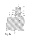
- Figs. 8a and 8b show in detail portions of a drawing ring 40 and a drawing ring mandrel 61 co-operating with the drawing ring when both of these devices are displaced by drive means (not shown in the Figures) to positions in which the gap 4 is formed between the drawing ring and the drawing ring mandrel.
- Fig. 8a shows the gap 4 without any plastic material being located therein
- fig. 8b shows the wall of the blank 1 on passage through the gap 4 formed by the drawing ring 40 and the drawing ring mandrel 61.
- the drawing ring 40 is shown in one embodiment in which it is composed of two part rings 42,43. Each drawing ring is provided with a channel 44,45 for conveying thermal medium.
- the drawing ring has a guide surface 46 facing towards the drawing ring mandrel 61, against which surface the material in the blank is pressed on passage through the gap 4.
- the guide surface makes an angle with the surface 60 of the drawing ring mandrel and merges into a drawing ring surface 41 located substantially parallel with the surface of the drawing ring mandrel.
- the surface 41 constitutes the bounding definition of the gap in that region of the gap where this is narrowest.
- the drawing ring mandrel is generally provided with channels 63 for thermal medium.
- Fig. 9 shows the container 2 formed from the blank once a trimming device 52 has cut away superfluous material at the open end 10 of the extended blank 1 (the future filling aperture).
- the three parts 30,31,32 from which the injection mould 3 is constructed are united and form the inner cavity 34 of the injection mould, with a form corresponding to the contemplated form or shape of the blank.
- a channel 33 runs through the forward end 30, and discharges in the inner cavity 34 in the region thereof where the emptying mouth 12 of the contemplated container is formed.
- the inner forming cavity 34 comprises two mutually interconnected part cavities, the one 34a for forming the blank body and the other 34b for forming the closure means 14 of the blank.
- An injection mould nozzle 35 is shown in connection with the channel 33.
- An arm 36 is displaceable by means (not shown) to and from the starting position illustrated in Fig. 3.
- Fig. 4 the injection mould is shown with the forward portion 30 separated from the intermediate portion 31 interconnected with the rear portion 32. In this position the mould is open and parts of the blank 1 are exposed.
- Fig. 5 shows the arm 36 displaced to a position in which the arm presses the closure means 14 against the emptying mouth or aperture 12 of the blank.
- the arm is moved to a position causing the arm, when traveling from said position to the position in Fig. 5, to displace closure means 14 in a pivotal motion from the position assumed by the closure means in Fig. 4 to the position assumed by the closure means in Fig. 5.
- FIG. 6 the intermediate portion 31 of the injection mould has been displaced from a position in which the intermediate portion abuts against the rear portion 32.
- the blank 1 has been removed from the male portion 37 which is located within the blank on injection moulding thereof.
- the arm 36 is moved back to its starting position.
- Fig. 7 shows the blank 1 placed between one or more heating means 50.
- a mandrel 51 is also inserted into the blank as a rule to constitute a supplementary heat source for the material during the heating cycle.
- the mandrel is generally provided with heat-conditioning means, for example channels for a thermal medium.
- Fig. 8 shows the blank 1a once a drawing ring 40 has passed the tubular portion of the blank in the axial direction thereof and during reduction of the material thickness of the tubular portion.
- the drawing ring is disposed to maintain a surface temperature in its surface 41,46 facing towards the plastic material which is adjustable to a level within the range of between approx. 50 and 70°C.
- the mandrel (drawing ring mandrel) 61 is disposed to be at least partly located within the blank 1.
- the drawing ring mandrel forms a gap 4 together with the drawing ring 40.
- the mandrel is disposed to maintain for the surface, facing the drawing ring 40 for forming the gap 4, a temperature which is adjustable at a level within the range of between approx. 50 and 100°C.
- the gap 4 has a minimum gap width which is less than the material thickness of the injection moulded blank.
- the gap width is within the order of magnitude of between 0.1 and 0.9 mm, preferably between 0.13 and 0.55 mm, and in special cases between 0.13 and 0.45 mm.
- the material thickness of the tubular portion of the blank substantially corresponds with the gap width of the gap employed in the reduction of the thickness of the material in the tubular portion of the blank.
- the size of the extension of the tubular portion and the size of the reduction are adapted to suit properties desired in the finished container.
- the size of the reduction is selected so as to lie within the range of between 2.5 and 5.0 times, preferably within a range of between 3.5 and 4.5 times.
- Fig. 9 shows the finished container (cf. Fig. 2) in position in the end station once trimming has taken place of the end region of the axially extended tubular portion of the blank 1a.
- the container 2 illustrated in Figs. 2 and 9 has a thin-walled tubular portion 23 which has, in its one end 20, an opening whose size (cross-section) corresponds to the inner cross-section of the tubular portion. This facilitates the supply of contents into the container. Closure of the filled container after filling is put into effect simply by means of a welding process, for example two heat punches which heat the material to fusion temperature.
- the thin-walled material rapidly assumes the form or shape which is determined by the form of the dies, as a rule a straight form, and rapidly arrives at the temperature which is necessary for the material to fuse together and form a tight seal.
- the container is of a form and construction which wholly correspond with that which it obtains as a blank in connection with the injection moulding.
- the thin wall of the tubular portion of the container entails that the material is relatively easily deformable and that emptying of the container will thereby be facilitated.
- thermoplastic materials in the practical application of the above described technology are polypropylene (PP), polyethylene terephthalate (PET), polyolefines (PE) and certain thermoplastic elastomers, for example styrene elastomers (SEBS).
- PP polypropylene
- PET polyethylene terephthalate
- PE polyolefines
- SEBS thermoplastic elastomers
- SEBS thermoplastic elastomers
- “Dead fold” properties are wholly unique properties in thin-walled plastic tubes. This ensures an almost complete emptying of the tube on use, which also prevents oxygen/air from being drawn back into the tube in connection with its being emptied.
Landscapes
- Engineering & Computer Science (AREA)
- Mechanical Engineering (AREA)
- Manufacturing & Machinery (AREA)
- Injection Moulding Of Plastics Or The Like (AREA)
- Moulds For Moulding Plastics Or The Like (AREA)
- Moulding By Coating Moulds (AREA)
Abstract
Description
- The present invention relates to a method and an apparatus for producing a tubular container according to the preambles to the respective independent claims. By tubular container it is meant a continuous walled container which has a cross-section taken through the wall of the container being substantially arbitrary e.g. circular, elliptical polygonal, having at least one corner, one flat surface, an inwardly curved surface etc. A round, oval or polysided container form embodiments of the invented container.
- In the injection moulding of tubular containers of plastic material, the maximum length which can be obtained for the tubular portion of the container is determined by the selected material and the wall thickness of the tubular portion. In addition, the wall thickness may not be less than approx. 0.5 mm irrespective of the plastic material employed in the injection moulding. This relationship is clarified further later in the body of this description.
- In the injection moulding of containers, the flow length of the supplied molten plastic material and, thereby, the unit formed in the injection moulding process is maximized by the material thickness. In purely practical terms, it has proved that injection moulded products having a wall thickness of less than 0.5 mm cannot be produced in mass production lines. Cf., for example, the book by Menges/Mohren, "How to Make Injection Molds", 1986, Hanser Publishers (ISBN 0-19-520744-0 Oxford University Press), p. 66.
- Tubular containers of plastic material have recently been adopted for use as tubes for, for example, toothpaste, handcreams etc. However, for the reasons outlined above it has been necessary to select material thicknesses for the tubular portion to be unnecessarily large or, otherwise it has been necessary to restrict the length of the tubular portion. WO-A-92/18318 discloses a method of producing a substantially tubular container of plastic material.
- The present invention relates to a technique in which, as compared with the prior art techniques, the length of the tubular portion of the container is extended by at most approx. 4 times, at the same time as the material thickness in the tubular portion is reduced by at most approx. 4 times. Simultaneously, the material properties of the tubular portion are improved, in particular the mechanical material properties. The material properties of the tubular portion of the container will be modified, implying, among other things, that the material in the walls of the mould portion will be softer and more readily mouldable than in prior art containers. Emptying of the contents from such containers will thereby be facilitated.
- This object is attained by means of the technique as disclosed in the characterizing clauses of the appended independent claims.
- The present invention realizes a considerable materials saving, with the result that the costs involved in producing such containers are drastically reduced as compared with that which applies to tubular containers produced according the prior art technique. Cost savings of the order of magnitude of 40% have been achieved.
- Expedient embodiments of the present invention are defined below in the appended subclaims.
- The present invention will now be described in greater detail hereinbelow with particular reference to a number of drawing figures, in which:
- Fig. 1
- shows a blank obtained by injection moulding;
- Fig. 2
- shows a container formed by extension of the blank;
- Figs. 3-6
- are cross-sections through an apparatus, the apparatus being illustrated in mutually subsequent production stages of the blank;
- Figs. 6-9
- show an apparatus for forming the blank by extending the tubular portion of the blank in different stages of the forming process; and
- Figs. 8a,b
- show parts of the apparatus of the figs. 7-9 for extending the tubular portion of the blank.
- Fig. 1 shows an axial cross-section through an injection moulded blank 1, comprising a
tubular portion 13 and anadjacent portion 19 including an emptying aperture ormouth 12. As a rule, the associated portion tapers towards themouth 12. The tubular portion and, thereby, the blank, is open at thatend 10 which is opposed to the emptying aperture ormouth 12. At its other end 11, i.e. in that end which encompasses the mouth, thetubular portion 13 connects to the taperingportion 19. Acloser means 14 included in the blank is shown as placed in a position where, as a rule, it sealingly abuts against material portions of the emptying aperture ormouth 12. The closure means 14 constitutes an integrated portion of the blank and is, via a hinge-like pivot 18, connected with the remainder of the blank. - Fig. 2 shows an axial cross-section through that
container 2 which is obtained once the blank illustrated in fig. 1 has been extended, in that the material thickness of the tubular portion of the blank has been reduced on the extension or prolongation of the tubular portion. The tubular portion of the container, formed by thetubular part 13 of the blank, has been givenreference numeral 23. The taperingportion 19 of the blank, together with the closure means 14 pivotally integrated with the tapering portion is not influenced by the forming process. Theend 20 which is opposed to the emptying aperture ormouth 12 is still open, while theother end 21 of the tubular portion connects integrally with the taperingportion 19. All parts which are included in thecontainer 2 constitute a unit in which the parts merge into one another without any mechanical joints or seams. In other words, the material in the container forms one single material piece (an integral unit). - Figs. 3-6 show a section through an injection mould 3 for forming plastic material to the blank 1. The injection mould 3 comprises a
forward portion 30, anintermediate portion 31 and arear portion 32. The portions of the injection mould together enclose a formingcavity 34. The Figures show the injection mould once the plastic material has been supplied into the formingcavity 34. - Figs. 7-8 schematically illustrate longitudinal sections through parts of an apparatus for extending the blank 1 formed in the injection mould 3.
- Fig. 7 shows that part of the apparatus where the
tubular portion 13 of the blank 1 is surrounded by heating means 50 which abut against the outer surface of the tubular portion. Amandrel 51 is generally inserted into the blank so as to stabilize the blank during the heating process. In certain embodiments, themandrel 51 is also provided with means for temperature conditioning of the blank. - Fig. 8 shows the blank 1a once the material in its
tubular portion 13 has passed through a gap 4 (cf. fig. 8a) for reduction of the material thickness under simultaneous extension of the blank. - Figs. 8a and 8b show in detail portions of a
drawing ring 40 and adrawing ring mandrel 61 co-operating with the drawing ring when both of these devices are displaced by drive means (not shown in the Figures) to positions in which thegap 4 is formed between the drawing ring and the drawing ring mandrel. Fig. 8a shows thegap 4 without any plastic material being located therein, and fig. 8b shows the wall of the blank 1 on passage through thegap 4 formed by thedrawing ring 40 and thedrawing ring mandrel 61. - In Figs. 8a,b the
drawing ring 40 is shown in one embodiment in which it is composed of twopart rings channel guide surface 46 facing towards thedrawing ring mandrel 61, against which surface the material in the blank is pressed on passage through thegap 4. The guide surface makes an angle with thesurface 60 of the drawing ring mandrel and merges into adrawing ring surface 41 located substantially parallel with the surface of the drawing ring mandrel. - The
surface 41 constitutes the bounding definition of the gap in that region of the gap where this is narrowest. The drawing ring mandrel is generally provided withchannels 63 for thermal medium. - Fig. 9 shows the
container 2 formed from the blank once a trimmingdevice 52 has cut away superfluous material at theopen end 10 of the extended blank 1 (the future filling aperture). - In Fig. 3, the three
parts inner cavity 34 of the injection mould, with a form corresponding to the contemplated form or shape of the blank. Achannel 33 runs through theforward end 30, and discharges in theinner cavity 34 in the region thereof where the emptyingmouth 12 of the contemplated container is formed. The inner formingcavity 34 comprises two mutually interconnected part cavities, the one 34a for forming the blank body and the other 34b for forming the closure means 14 of the blank. Aninjection mould nozzle 35 is shown in connection with thechannel 33. Anarm 36 is displaceable by means (not shown) to and from the starting position illustrated in Fig. 3. - In Fig. 4, the injection mould is shown with the
forward portion 30 separated from theintermediate portion 31 interconnected with therear portion 32. In this position the mould is open and parts of the blank 1 are exposed. - Fig. 5 shows the
arm 36 displaced to a position in which the arm presses the closure means 14 against the emptying mouth oraperture 12 of the blank. During displacement from the position which is shown in Figs. 3 and 4 the arm is moved to a position causing the arm, when traveling from said position to the position in Fig. 5, to displace closure means 14 in a pivotal motion from the position assumed by the closure means in Fig. 4 to the position assumed by the closure means in Fig. 5. - In Fig. 6, the
intermediate portion 31 of the injection mould has been displaced from a position in which the intermediate portion abuts against therear portion 32. The blank 1 has been removed from themale portion 37 which is located within the blank on injection moulding thereof. Thearm 36 is moved back to its starting position. - Fig. 7 shows the blank 1 placed between one or more heating means 50. In certain practical applications, in particular in large material thickness of the
tubular portion 13 of the blank, amandrel 51 is also inserted into the blank as a rule to constitute a supplementary heat source for the material during the heating cycle. The mandrel is generally provided with heat-conditioning means, for example channels for a thermal medium. - Fig. 8 shows the blank 1a once a drawing
ring 40 has passed the tubular portion of the blank in the axial direction thereof and during reduction of the material thickness of the tubular portion. The drawing ring is disposed to maintain a surface temperature in itssurface - The mandrel (drawing ring mandrel) 61 is disposed to be at least partly located within the blank 1. The drawing ring mandrel forms a
gap 4 together with thedrawing ring 40. The mandrel is disposed to maintain for the surface, facing thedrawing ring 40 for forming thegap 4, a temperature which is adjustable at a level within the range of between approx. 50 and 100°C. - The
gap 4 has a minimum gap width which is less than the material thickness of the injection moulded blank. The gap width is within the order of magnitude of between 0.1 and 0.9 mm, preferably between 0.13 and 0.55 mm, and in special cases between 0.13 and 0.45 mm. After passage of the gap, the material thickness of the tubular portion of the blank substantially corresponds with the gap width of the gap employed in the reduction of the thickness of the material in the tubular portion of the blank. - The size of the extension of the tubular portion and the size of the reduction are adapted to suit properties desired in the finished container. The size of the reduction is selected so as to lie within the range of between 2.5 and 5.0 times, preferably within a range of between 3.5 and 4.5 times.
- Fig. 9 shows the finished container (cf. Fig. 2) in position in the end station once trimming has taken place of the end region of the axially extended tubular portion of the blank 1a. As a result of this trimming operation, a substantially uniform defining edge will be achieved in respect of the opening or aperture in the
end region 20 opposed to the emptying aperture ormouth 12. - The
container 2 illustrated in Figs. 2 and 9 has a thin-walled tubular portion 23 which has, in its oneend 20, an opening whose size (cross-section) corresponds to the inner cross-section of the tubular portion. This facilitates the supply of contents into the container. Closure of the filled container after filling is put into effect simply by means of a welding process, for example two heat punches which heat the material to fusion temperature. The thin-walled material rapidly assumes the form or shape which is determined by the form of the dies, as a rule a straight form, and rapidly arrives at the temperature which is necessary for the material to fuse together and form a tight seal. At itsother end 21, the container is of a form and construction which wholly correspond with that which it obtains as a blank in connection with the injection moulding. The thin wall of the tubular portion of the container entails that the material is relatively easily deformable and that emptying of the container will thereby be facilitated. - Preferred thermoplastic materials in the practical application of the above described technology are polypropylene (PP), polyethylene terephthalate (PET), polyolefines (PE) and certain thermoplastic elastomers, for example styrene elastomers (SEBS). It will be obvious to a person skilled in the art that the technique as disclosed in the foregoing is generally applicable to all plastic materials which have similar reformation properties, i.e. materials possessing properties corresponding to those required for a container to be formed in the application of the above described technology.
- It has surprisingly proved that, for certain given materials, for example polypropylene (PP), polyethylene terephthalate (PET), and polyolefines (PE), it is possible to produce containers whose tubular portion has so-called "dead fold" properties. To achieve such properties, a material thickness is selected for the tubular portion of the container within the range of between 0.1 and 0.15 mm. The term "dead fold" properties is taken to signify those properties which are known from tubes of aluminium, i.e. that the tube can retain its form after compression. The resilient return action which is known from earlier tubes of plastic material will thereby thus be avoided.
- "Dead fold" properties are wholly unique properties in thin-walled plastic tubes. This ensures an almost complete emptying of the tube on use, which also prevents oxygen/air from being drawn back into the tube in connection with its being emptied.
- The above detailed description has referred to but a limited number of embodiments of the present invention, but a person skilled in the art will readily perceive that the present invention encompasses a large number of embodiments included by the scope of the claims.
Claims (11)
- A method of producing a substantially tubular container (2) of plastic material, in which the container is open at its one end (20), and is, at its other end (21), provided with an emptying aperture or mouth (22), in which the container forms a substantially cylindrical wall (23) between its open end (20) and its other end (21), in which closure means (24) constitute a part integral with the other end, and in which, in production of the container, a blank (1) is injected in an injection mould (3), characterized in that the plastic material is supplied in the molten state to the injection mould (3) and forms therein a blank (1) comprising a blank body (15) with a tubular portion (16) open at its one end (11) and provided at its other end (10) with an aperture (12) constituting the emptying aperture or mouth (22) of the future container; that, on supply of the plastic material to the injection mould, there is formed a closure means (14) integral with the other end (10) of the blank body (15) and projecting from the other end (10) of the blank body, said closure means constituting the closure device (24) of the future container; that, after forming of the blank, the tubular portion (16) of the blank body (15) is displaced through an annular gap (4) under reduction of the material thickness of the tubular portion (16); that the size of said reduction is located within the range of between 2.5 and 5.0 times, preferably within the range of between 3.5 and 4.5 times; that, on passage of the gap (4), there is formed an extended blank body (15a); that the extended blank body is severed in its end (10) opposed to the emptying aperture or mouth (12), for the formation of a substantially uniform edge whereby the container body (25) is completed, and
that, on removal of the blank (1) from the injection mould (3), a mechanical device (36) displaces the closure means (14) to a position in which all parts of the closure means (14) are located at a distance from the geometric centre axis (17) of the blank at most amounting to the distance between the geometric centre axis (47) of the gap and the surface (41) of the gap located most proximal the centre axis. - The method as claimed in claim 1, characterized in that, on removal of the blank (1) from the injection mould (3), a mechanical device (36) displaces the closure means (14) to a position in which all parts of the closure means (14) are located at a distance from the geometric centre axis (17) of the blank at most amounting to the distance between the geometric centre axis (47) of the gap and the surface (41) of the gap located most distant from the centre axis.
- The method as claimed in any of claims 1 - 2, characterized in that at least a part of the material in the tubular portion of the blank is, by abutment against a hot mechanical surface, adjusted to an elevated temperature before the tubular portion (16) of the body of the blank is displaced through the gap (4).
- The method as claimed in any of claims 1 - 2, characterized in that the gap width of the gap (4) is selected such that, after passage of the gap, the material thickness of the material in the tubular portion of the blank (15) is located in the range of between 0.1 and 0.9 mm, preferably between 0.13 and 0.55 and, in special cases, in the range of between 0.13 and 0.45 mm.
- The method as claimed in any of the preceding claims, characterized in that, on forming of the container (2), the material in the tubular portion (13) of the blank (1) is given reduced thickness adapted to the material in question, and entailing that the material obtains "dead fold" properties.
- The method as claimed in any of the preceding claims, characterized in that, on forming of the container (2), the thickness of the material in the tubular portion (13) of the blank (1) is reduced to a value within the range of between 0.1 and 0.15 mm.
- The method as claimed in any of the preceding claims where the tubular part is substantially circular in shape.
- An apparatus for realizing the method according to any of the preceding claims, characterized in that the apparatus comprises an injection mould with an injection nozzle (35), a mould (3) comprising two part cavities (34a,b), a drawing ring (40) surrounding a mandrel (61) and forming a gap (4) between itself and the mandrel, and drive means for relative displacement of the drawing ring (40) and the mandrel (61) in the longitudinal direction of the mandrel while maintaining the dimensions of the gap (4) existing between the drawing ring and the mandrel.
- The apparatus as claimed in claim 8, characterized in that the parts (35,3,34a,34b,40,61) included in the apparatus form a composite unit.
- A container (2) of plastic material formed by reforming an injection moulded blank (1) in which the container includes a tubular portion (23) and a portion (19) integral therewith and including an emptying aperture or mouth (12), characterized in that the material in the tubular portion (23) is of a thickness which is in the range of between 0.1 and 0.15 mm.
- The container as claimed in claim 10 wherein said tubular portion is substantially circular in shape.
Applications Claiming Priority (3)
| Application Number | Priority Date | Filing Date | Title |
|---|---|---|---|
| SE9500455A SE523785C2 (en) | 1995-02-07 | 1995-02-07 | Method and apparatus for producing a tubular container with closure means |
| SE9500455 | 1995-02-07 | ||
| PCT/SE1996/000139 WO1996024483A1 (en) | 1995-02-07 | 1996-02-06 | Method and apparatus for producing a tubular container with closure means |
Publications (2)
| Publication Number | Publication Date |
|---|---|
| EP0808242A1 EP0808242A1 (en) | 1997-11-26 |
| EP0808242B1 true EP0808242B1 (en) | 2003-05-02 |
Family
ID=20397133
Family Applications (1)
| Application Number | Title | Priority Date | Filing Date |
|---|---|---|---|
| EP96902569A Expired - Lifetime EP0808242B1 (en) | 1995-02-07 | 1996-02-06 | Method and apparatus for producing a tubular container with closure means |
Country Status (10)
| Country | Link |
|---|---|
| US (1) | US6340440B1 (en) |
| EP (1) | EP0808242B1 (en) |
| AU (1) | AU4683296A (en) |
| BR (1) | BR9607030A (en) |
| CA (1) | CA2212410A1 (en) |
| CO (1) | CO4480766A1 (en) |
| DE (1) | DE69627824T2 (en) |
| IN (1) | IN192267B (en) |
| SE (1) | SE523785C2 (en) |
| WO (1) | WO1996024483A1 (en) |
Families Citing this family (13)
| Publication number | Priority date | Publication date | Assignee | Title |
|---|---|---|---|---|
| US5769277A (en) * | 1996-07-11 | 1998-06-23 | Aptargroup, Inc. | Dispensing closure having a force-directing removable seal |
| US5992668A (en) * | 1996-07-11 | 1999-11-30 | Aptargroup, Inc. | Sealed dispensing closure with a sealed penetrator |
| US5927566A (en) * | 1996-07-11 | 1999-07-27 | Aptargroup, Inc. | One-piece dispensing system and method for making same |
| US5755360A (en) * | 1996-07-11 | 1998-05-26 | Aptargroup, Inc. | Multi-material, multi-shot, injection molded dispensing closure having a removable seal |
| US5853109A (en) * | 1998-04-29 | 1998-12-29 | Aptargroup, Inc. | Dispensing structure with displaceable penetrator and bistable cover actuator |
| EP1114780B2 (en) * | 2000-01-07 | 2008-09-03 | The Procter & Gamble Company | One-piece dosing cap |
| CH692283A5 (en) * | 2000-10-06 | 2002-04-30 | Schoettli Ag | Method and device for closing plastic closures to a multiple injection tool of a spray gun. |
| AU2002354090A1 (en) * | 2001-11-19 | 2003-06-23 | Gram Technology Aps | Tool with closing mechanism and method of manufacturing preferably plastic parts with hinges |
| US7168149B2 (en) * | 2002-09-13 | 2007-01-30 | Husky Injection Molding Systems Ltd. | Apparatus for closing a hinged molded part |
| EP1512513A3 (en) * | 2003-09-08 | 2005-05-18 | Easy Plast SRL | Injection mould for obtaining bottles of plastics material |
| US20050269744A1 (en) * | 2004-06-07 | 2005-12-08 | Lonsway Michael J | Stretched container and method of manufacture |
| ITRE20050090A1 (en) * | 2005-07-22 | 2007-01-23 | Sacmi | MOLD FOR COMPRESSION FORMING OF A CAPSULE WITH HINGED LID |
| ES2830756T3 (en) * | 2015-03-12 | 2021-06-04 | Husky Injection Molding Systems Ltd | Injection mold featuring a lid closure device in the mold |
Family Cites Families (24)
| Publication number | Priority date | Publication date | Assignee | Title |
|---|---|---|---|---|
| US3786755A (en) * | 1971-11-18 | 1974-01-22 | Remington Arms Co Inc | Plastic cartridge casing |
| JPS5334868A (en) | 1976-09-13 | 1978-03-31 | Sumitomo Electric Industries | Fine porous tube |
| ZA776629B (en) * | 1976-11-25 | 1978-08-30 | Metal Box Co Ltd | Improvements relating to collapsible tubular containers |
| SE429317B (en) * | 1980-05-29 | 1983-08-29 | Plm Ab | SETTING ASTADCOMMENDING ANY POLYETHYLTENE PREPARATE OR ITS LIKE THERMOPLASTIC MATERIAL AS A DEVICE FOR THIS |
| US4419320A (en) * | 1980-10-22 | 1983-12-06 | The Goodyear Tire & Rubber Company | Novel process for deep stretch forming of polyesters |
| US4340352A (en) | 1980-12-31 | 1982-07-20 | Global Precision Inc. | Hinge exercising mechanism |
| US4354996A (en) * | 1981-01-09 | 1982-10-19 | Toyo Seikan Kaisha, Ltd. | Method for making a plastic container |
| DE3205076A1 (en) * | 1981-02-13 | 1982-11-25 | Kurosaki Refractories Co., Ltd., Kitakyushu, Fukuoka | Process for producing an extrusion moulding and material composition for this |
| SE428774B (en) * | 1981-11-26 | 1983-07-25 | Plm Ab | SET TO ASTADCOMMA AND CONTAINER |
| US4519977A (en) | 1982-09-27 | 1985-05-28 | Toyo Seikan Kaisha Limited | Method for making a plastic container |
| SE435596B (en) | 1982-10-14 | 1984-10-08 | Plm Ab | SET FOR THE PREPARATION OF AN ARTICLE THROUGH THE SHAPING AND CRYSTALLIZATION OF MATERIAL IN THE WALL WITH A THEME OF THERMOPLASTIC MATERIAL WHEN IT'S THICKNESS REDUCTION AND MECHANICAL FORMING ORGANIC |
| US4563325A (en) | 1983-05-20 | 1986-01-07 | Shell Oil Company | Forming plastic articles in solid state |
| DE3582744D1 (en) | 1984-03-30 | 1991-06-13 | Nat Res Dev | TUBULAR ITEMS. |
| SE450630B (en) | 1984-12-14 | 1987-07-13 | Petainer Sa | SET AND DEVICE FOR MANUFACTURING A PLASTIC CONTAINER THROUGH REFORMING A PRINCIPLES |
| DE3603843A1 (en) | 1986-02-07 | 1987-08-20 | Krupp Corpoplast Masch | METHOD AND DEVICE FOR PRODUCING HOLLOW BODIES FROM THERMOPLASTIC PLASTIC |
| DE3603846A1 (en) | 1986-02-07 | 1987-08-20 | Krupp Corpoplast Masch | METHOD FOR PRODUCING HOLLOW BODIES FROM THERMOPLASTIC PLASTIC |
| US4783056A (en) * | 1986-11-10 | 1988-11-08 | Abrams Robert S | Process for making an aseptic vial and cap |
| US4930644A (en) | 1988-12-22 | 1990-06-05 | Robbins Edward S Iii | Thin film container with removable lid and related process |
| US5039462A (en) | 1990-01-08 | 1991-08-13 | Aluminum Company Of America | Method and apparatus for producing biaxially oriented polymer sheet |
| SE468666B (en) * | 1990-09-27 | 1993-03-01 | Plm Ab | SET AND DEVICE TO CRYSTALLIZE AMORFT PLASTIC MATERIAL IN A SUBSTANCE |
| US5656225A (en) | 1991-04-11 | 1997-08-12 | Plm Ab | Method of producing a container of orientable plastic material |
| SE469882B (en) * | 1991-04-11 | 1993-10-04 | Plm Ab | Container of plastic material where parts of the container have monoaxially oriented material, and manufacture of the container |
| US5573129A (en) | 1993-02-19 | 1996-11-12 | Fuji Photo Film Co., Ltd. | Collapsible container for a liquid |
| IT1266279B1 (en) * | 1993-03-05 | 1996-12-27 | Gd Spa | METHOD FOR MAKING A RIGID PACKAGE WITH HINGED LID FOR EXTENDED ITEMS, PARTICULARLY CIGARETTES. |
-
1995
- 1995-02-07 SE SE9500455A patent/SE523785C2/en not_active IP Right Cessation
-
1996
- 1996-02-06 DE DE69627824T patent/DE69627824T2/en not_active Expired - Lifetime
- 1996-02-06 AU AU46832/96A patent/AU4683296A/en not_active Abandoned
- 1996-02-06 CO CO96005170A patent/CO4480766A1/en unknown
- 1996-02-06 WO PCT/SE1996/000139 patent/WO1996024483A1/en not_active Ceased
- 1996-02-06 EP EP96902569A patent/EP0808242B1/en not_active Expired - Lifetime
- 1996-02-06 CA CA002212410A patent/CA2212410A1/en not_active Abandoned
- 1996-02-06 IN IN186MA1996 patent/IN192267B/en unknown
- 1996-02-06 BR BR9607030A patent/BR9607030A/en not_active Application Discontinuation
-
2000
- 2000-10-10 US US09/685,365 patent/US6340440B1/en not_active Expired - Fee Related
Also Published As
| Publication number | Publication date |
|---|---|
| US6340440B1 (en) | 2002-01-22 |
| CO4480766A1 (en) | 1997-07-09 |
| WO1996024483A1 (en) | 1996-08-15 |
| AU4683296A (en) | 1996-08-27 |
| SE9500455D0 (en) | 1995-02-07 |
| DE69627824D1 (en) | 2003-06-05 |
| EP0808242A1 (en) | 1997-11-26 |
| CA2212410A1 (en) | 1996-08-15 |
| IN192267B (en) | 2004-03-27 |
| BR9607030A (en) | 1997-11-04 |
| SE9500455L (en) | 1996-08-08 |
| DE69627824T2 (en) | 2003-11-06 |
| SE523785C2 (en) | 2004-05-18 |
Similar Documents
| Publication | Publication Date | Title |
|---|---|---|
| US6340440B1 (en) | Process of making a tubular container | |
| US5069856A (en) | Method of forming a headed thermoplastic tube | |
| CA2398364C (en) | Plastic container and method of producing the same | |
| US5392950A (en) | Plastic container with a completely sealed handle | |
| EP0422436B1 (en) | Plastic bottle with reinforced concave bottom | |
| CZ289041B6 (en) | Multi-layer preform, process for forming such preform and a multi-layer container manufactured from the preform | |
| US4086314A (en) | Method of and apparatus for the production of thermoplastic containers | |
| JPS649225B2 (en) | ||
| US5203379A (en) | Headed thermoplastic tube | |
| EP0069249A1 (en) | Tube package | |
| EP3634714B1 (en) | Methods of forming unitary serological pipettes | |
| US7153466B2 (en) | Method and apparatus for blow-molding an article having a solid radially outwardly projecting flange | |
| JP2003104404A (en) | Resin tubular container and preform thereof | |
| CN1226133C (en) | Extrusion Blow Molding Method | |
| AU2000277025B2 (en) | Improved container and method and apparatus for forming the container | |
| US5013517A (en) | Method of blow molding integral press-lock container | |
| MXPA97006034A (en) | Method and apparatus for producing a tubular container with cie media | |
| US4333904A (en) | Forming a mouthpiece on a preform | |
| WO1995001255A1 (en) | Collapsible package | |
| JP4710120B2 (en) | Blow molding method and apparatus for internally reinforced hollow container | |
| TWI252804B (en) | Method for manufacturing integrally formed container and label | |
| CN210173973U (en) | Intermediate for manufacturing energy-saving rotatable hoisting ring bottle blank | |
| JPH0272928A (en) | Manufacture of stretched blow bottle with handle | |
| JP3243574B2 (en) | Blow forming method and apparatus for bent pipe joint | |
| JPH11105107A (en) | Partition wall bag and manufacturing method thereof |
Legal Events
| Date | Code | Title | Description |
|---|---|---|---|
| PUAI | Public reference made under article 153(3) epc to a published international application that has entered the european phase |
Free format text: ORIGINAL CODE: 0009012 |
|
| 17P | Request for examination filed |
Effective date: 19970829 |
|
| AK | Designated contracting states |
Kind code of ref document: A1 Designated state(s): CH DE DK FR GB IT LI SE |
|
| 17Q | First examination report despatched |
Effective date: 19990709 |
|
| GRAH | Despatch of communication of intention to grant a patent |
Free format text: ORIGINAL CODE: EPIDOS IGRA |
|
| GRAH | Despatch of communication of intention to grant a patent |
Free format text: ORIGINAL CODE: EPIDOS IGRA |
|
| RAP1 | Party data changed (applicant data changed or rights of an application transferred) |
Owner name: OENNEBO, AGNETA Owner name: PLASTECH A.P.S. |
|
| GRAA | (expected) grant |
Free format text: ORIGINAL CODE: 0009210 |
|
| AK | Designated contracting states |
Designated state(s): CH DE DK FR GB IT LI SE |
|
| PG25 | Lapsed in a contracting state [announced via postgrant information from national office to epo] |
Ref country code: IT Free format text: LAPSE BECAUSE OF FAILURE TO SUBMIT A TRANSLATION OF THE DESCRIPTION OR TO PAY THE FEE WITHIN THE PRESCRIBED TIME-LIMIT;WARNING: LAPSES OF ITALIAN PATENTS WITH EFFECTIVE DATE BEFORE 2007 MAY HAVE OCCURRED AT ANY TIME BEFORE 2007. THE CORRECT EFFECTIVE DATE MAY BE DIFFERENT FROM THE ONE RECORDED. Effective date: 20030502 |
|
| REG | Reference to a national code |
Ref country code: GB Ref legal event code: FG4D |
|
| REG | Reference to a national code |
Ref country code: CH Ref legal event code: EP |
|
| REF | Corresponds to: |
Ref document number: 69627824 Country of ref document: DE Date of ref document: 20030605 Kind code of ref document: P |
|
| PG25 | Lapsed in a contracting state [announced via postgrant information from national office to epo] |
Ref country code: SE Free format text: LAPSE BECAUSE OF FAILURE TO SUBMIT A TRANSLATION OF THE DESCRIPTION OR TO PAY THE FEE WITHIN THE PRESCRIBED TIME-LIMIT Effective date: 20030802 Ref country code: DK Free format text: LAPSE BECAUSE OF FAILURE TO SUBMIT A TRANSLATION OF THE DESCRIPTION OR TO PAY THE FEE WITHIN THE PRESCRIBED TIME-LIMIT Effective date: 20030802 |
|
| REG | Reference to a national code |
Ref country code: CH Ref legal event code: AEN Free format text: DAS PATENT IST AUF GRUND DES WEITERBEHANDLUNGSANTRAGS VOM 08.10.2003 REAKTIVIERT WORDEN. |
|
| REG | Reference to a national code |
Ref country code: CH Ref legal event code: NV Representative=s name: AVV. FRANCO PAGANI |
|
| ET | Fr: translation filed | ||
| PLBE | No opposition filed within time limit |
Free format text: ORIGINAL CODE: 0009261 |
|
| STAA | Information on the status of an ep patent application or granted ep patent |
Free format text: STATUS: NO OPPOSITION FILED WITHIN TIME LIMIT |
|
| 26N | No opposition filed |
Effective date: 20040203 |
|
| REG | Reference to a national code |
Ref country code: CH Ref legal event code: PFA Owner name: PLASTECH A.P.S. Free format text: PLASTECH A.P.S.#OESTRE HAVNEVEJ 23#5700 SVENDBORG (DK) -TRANSFER TO- PLASTECH A.P.S.#OESTRE HAVNEVEJ 23#5700 SVENDBORG (DK) |
|
| PGFP | Annual fee paid to national office [announced via postgrant information from national office to epo] |
Ref country code: FR Payment date: 20110317 Year of fee payment: 16 |
|
| PGFP | Annual fee paid to national office [announced via postgrant information from national office to epo] |
Ref country code: GB Payment date: 20110224 Year of fee payment: 16 |
|
| GBPC | Gb: european patent ceased through non-payment of renewal fee |
Effective date: 20120206 |
|
| REG | Reference to a national code |
Ref country code: FR Ref legal event code: ST Effective date: 20121031 |
|
| PG25 | Lapsed in a contracting state [announced via postgrant information from national office to epo] |
Ref country code: GB Free format text: LAPSE BECAUSE OF NON-PAYMENT OF DUE FEES Effective date: 20120206 Ref country code: FR Free format text: LAPSE BECAUSE OF NON-PAYMENT OF DUE FEES Effective date: 20120229 |
|
| PGFP | Annual fee paid to national office [announced via postgrant information from national office to epo] |
Ref country code: DE Payment date: 20130221 Year of fee payment: 18 |
|
| PGFP | Annual fee paid to national office [announced via postgrant information from national office to epo] |
Ref country code: CH Payment date: 20140214 Year of fee payment: 19 |
|
| REG | Reference to a national code |
Ref country code: DE Ref legal event code: R119 Ref document number: 69627824 Country of ref document: DE |
|
| REG | Reference to a national code |
Ref country code: DE Ref legal event code: R119 Ref document number: 69627824 Country of ref document: DE Effective date: 20140902 |
|
| PG25 | Lapsed in a contracting state [announced via postgrant information from national office to epo] |
Ref country code: DE Free format text: LAPSE BECAUSE OF NON-PAYMENT OF DUE FEES Effective date: 20140902 |
|
| REG | Reference to a national code |
Ref country code: CH Ref legal event code: PL |
|
| PG25 | Lapsed in a contracting state [announced via postgrant information from national office to epo] |
Ref country code: CH Free format text: LAPSE BECAUSE OF NON-PAYMENT OF DUE FEES Effective date: 20150228 Ref country code: LI Free format text: LAPSE BECAUSE OF NON-PAYMENT OF DUE FEES Effective date: 20150228 |