EP0808141B1 - Method and apparatus for sodding microvessel cells onto a synthetic vascular graft - Google Patents
Method and apparatus for sodding microvessel cells onto a synthetic vascular graft Download PDFInfo
- Publication number
- EP0808141B1 EP0808141B1 EP96907860A EP96907860A EP0808141B1 EP 0808141 B1 EP0808141 B1 EP 0808141B1 EP 96907860 A EP96907860 A EP 96907860A EP 96907860 A EP96907860 A EP 96907860A EP 0808141 B1 EP0808141 B1 EP 0808141B1
- Authority
- EP
- European Patent Office
- Prior art keywords
- sodding
- graft
- cells
- assembly
- inlet
- Prior art date
- Legal status (The legal status is an assumption and is not a legal conclusion. Google has not performed a legal analysis and makes no representation as to the accuracy of the status listed.)
- Expired - Lifetime
Links
- 238000000034 method Methods 0.000 title claims description 40
- 230000002792 vascular Effects 0.000 title claims description 21
- 210000004088 microvessel Anatomy 0.000 title description 44
- 239000007788 liquid Substances 0.000 claims description 39
- 238000004220 aggregation Methods 0.000 claims description 22
- 230000002776 aggregation Effects 0.000 claims description 22
- 239000008188 pellet Substances 0.000 claims description 22
- 239000012530 fluid Substances 0.000 claims description 18
- 239000000463 material Substances 0.000 claims description 7
- 238000007789 sealing Methods 0.000 claims description 7
- 229910001220 stainless steel Inorganic materials 0.000 claims description 6
- 238000010992 reflux Methods 0.000 claims description 5
- 238000011010 flushing procedure Methods 0.000 claims description 3
- 229920000052 poly(p-xylylene) Polymers 0.000 claims description 2
- 239000002861 polymer material Substances 0.000 claims description 2
- 125000006850 spacer group Chemical group 0.000 claims description 2
- 238000001914 filtration Methods 0.000 claims 1
- 239000010935 stainless steel Substances 0.000 claims 1
- 210000004027 cell Anatomy 0.000 description 93
- 210000002889 endothelial cell Anatomy 0.000 description 42
- 210000001519 tissue Anatomy 0.000 description 24
- 239000003708 ampul Substances 0.000 description 19
- 238000000151 deposition Methods 0.000 description 16
- 230000008021 deposition Effects 0.000 description 15
- 230000008569 process Effects 0.000 description 14
- 238000005516 engineering process Methods 0.000 description 13
- 238000002955 isolation Methods 0.000 description 7
- 238000012545 processing Methods 0.000 description 6
- 210000001789 adipocyte Anatomy 0.000 description 5
- 238000003306 harvesting Methods 0.000 description 5
- 238000007443 liposuction Methods 0.000 description 5
- 238000000926 separation method Methods 0.000 description 5
- 210000002966 serum Anatomy 0.000 description 5
- 230000003068 static effect Effects 0.000 description 5
- 230000029087 digestion Effects 0.000 description 4
- 239000012634 fragment Substances 0.000 description 4
- 238000001000 micrograph Methods 0.000 description 4
- 239000002002 slurry Substances 0.000 description 4
- 241000816129 Alcha Species 0.000 description 3
- 238000013019 agitation Methods 0.000 description 3
- 230000036760 body temperature Effects 0.000 description 3
- 230000007812 deficiency Effects 0.000 description 3
- 230000003511 endothelial effect Effects 0.000 description 3
- 210000003743 erythrocyte Anatomy 0.000 description 3
- 239000011148 porous material Substances 0.000 description 3
- 230000002829 reductive effect Effects 0.000 description 3
- 210000003855 cell nucleus Anatomy 0.000 description 2
- 238000010276 construction Methods 0.000 description 2
- 230000001419 dependent effect Effects 0.000 description 2
- 230000000694 effects Effects 0.000 description 2
- 230000006862 enzymatic digestion Effects 0.000 description 2
- 230000002255 enzymatic effect Effects 0.000 description 2
- 238000002360 preparation method Methods 0.000 description 2
- 239000007787 solid Substances 0.000 description 2
- 239000000725 suspension Substances 0.000 description 2
- 230000002885 thrombogenetic effect Effects 0.000 description 2
- 238000012549 training Methods 0.000 description 2
- 206010067484 Adverse reaction Diseases 0.000 description 1
- 241000272525 Anas platyrhynchos Species 0.000 description 1
- 102000029816 Collagenase Human genes 0.000 description 1
- 108060005980 Collagenase Proteins 0.000 description 1
- 102000004190 Enzymes Human genes 0.000 description 1
- 108090000790 Enzymes Proteins 0.000 description 1
- 239000004593 Epoxy Substances 0.000 description 1
- 208000007536 Thrombosis Diseases 0.000 description 1
- 210000000577 adipose tissue Anatomy 0.000 description 1
- 230000006838 adverse reaction Effects 0.000 description 1
- 230000015572 biosynthetic process Effects 0.000 description 1
- 239000010836 blood and blood product Substances 0.000 description 1
- 210000000601 blood cell Anatomy 0.000 description 1
- 230000017531 blood circulation Effects 0.000 description 1
- 229940125691 blood product Drugs 0.000 description 1
- 210000001124 body fluid Anatomy 0.000 description 1
- 239000010839 body fluid Substances 0.000 description 1
- 229960002424 collagenase Drugs 0.000 description 1
- 238000004891 communication Methods 0.000 description 1
- 210000001608 connective tissue cell Anatomy 0.000 description 1
- 238000012258 culturing Methods 0.000 description 1
- 230000001934 delay Effects 0.000 description 1
- 239000006185 dispersion Substances 0.000 description 1
- 229940088598 enzyme Drugs 0.000 description 1
- 210000002919 epithelial cell Anatomy 0.000 description 1
- 229920006332 epoxy adhesive Polymers 0.000 description 1
- 238000000605 extraction Methods 0.000 description 1
- 230000002349 favourable effect Effects 0.000 description 1
- 238000010438 heat treatment Methods 0.000 description 1
- 238000002513 implantation Methods 0.000 description 1
- 230000006872 improvement Effects 0.000 description 1
- 239000012678 infectious agent Substances 0.000 description 1
- 230000036512 infertility Effects 0.000 description 1
- 238000011005 laboratory method Methods 0.000 description 1
- 239000006194 liquid suspension Substances 0.000 description 1
- 238000004519 manufacturing process Methods 0.000 description 1
- 238000002156 mixing Methods 0.000 description 1
- 230000036961 partial effect Effects 0.000 description 1
- 230000001681 protective effect Effects 0.000 description 1
- 238000011084 recovery Methods 0.000 description 1
- 230000009467 reduction Effects 0.000 description 1
- 230000002441 reversible effect Effects 0.000 description 1
- 230000006641 stabilisation Effects 0.000 description 1
- 238000011105 stabilization Methods 0.000 description 1
- 238000001356 surgical procedure Methods 0.000 description 1
- 238000012360 testing method Methods 0.000 description 1
- 238000012546 transfer Methods 0.000 description 1
- 238000009827 uniform distribution Methods 0.000 description 1
- 238000011144 upstream manufacturing Methods 0.000 description 1
Images


Classifications
-
- A—HUMAN NECESSITIES
- A61—MEDICAL OR VETERINARY SCIENCE; HYGIENE
- A61F—FILTERS IMPLANTABLE INTO BLOOD VESSELS; PROSTHESES; DEVICES PROVIDING PATENCY TO, OR PREVENTING COLLAPSING OF, TUBULAR STRUCTURES OF THE BODY, e.g. STENTS; ORTHOPAEDIC, NURSING OR CONTRACEPTIVE DEVICES; FOMENTATION; TREATMENT OR PROTECTION OF EYES OR EARS; BANDAGES, DRESSINGS OR ABSORBENT PADS; FIRST-AID KITS
- A61F2/00—Filters implantable into blood vessels; Prostheses, i.e. artificial substitutes or replacements for parts of the body; Appliances for connecting them with the body; Devices providing patency to, or preventing collapsing of, tubular structures of the body, e.g. stents
- A61F2/02—Prostheses implantable into the body
- A61F2/04—Hollow or tubular parts of organs, e.g. bladders, tracheae, bronchi or bile ducts
- A61F2/06—Blood vessels
- A61F2/062—Apparatus for the production of blood vessels made from natural tissue or with layers of living cells
-
- A—HUMAN NECESSITIES
- A61—MEDICAL OR VETERINARY SCIENCE; HYGIENE
- A61L—METHODS OR APPARATUS FOR STERILISING MATERIALS OR OBJECTS IN GENERAL; DISINFECTION, STERILISATION OR DEODORISATION OF AIR; CHEMICAL ASPECTS OF BANDAGES, DRESSINGS, ABSORBENT PADS OR SURGICAL ARTICLES; MATERIALS FOR BANDAGES, DRESSINGS, ABSORBENT PADS OR SURGICAL ARTICLES
- A61L27/00—Materials for grafts or prostheses or for coating grafts or prostheses
- A61L27/50—Materials characterised by their function or physical properties, e.g. injectable or lubricating compositions, shape-memory materials, surface modified materials
- A61L27/507—Materials characterised by their function or physical properties, e.g. injectable or lubricating compositions, shape-memory materials, surface modified materials for artificial blood vessels
-
- Y—GENERAL TAGGING OF NEW TECHNOLOGICAL DEVELOPMENTS; GENERAL TAGGING OF CROSS-SECTIONAL TECHNOLOGIES SPANNING OVER SEVERAL SECTIONS OF THE IPC; TECHNICAL SUBJECTS COVERED BY FORMER USPC CROSS-REFERENCE ART COLLECTIONS [XRACs] AND DIGESTS
- Y10—TECHNICAL SUBJECTS COVERED BY FORMER USPC
- Y10S—TECHNICAL SUBJECTS COVERED BY FORMER USPC CROSS-REFERENCE ART COLLECTIONS [XRACs] AND DIGESTS
- Y10S623/00—Prosthesis, i.e. artificial body members, parts thereof, or aids and accessories therefor
- Y10S623/92—Method or apparatus for preparing or treating prosthetic
- Y10S623/921—Blood vessel
Definitions
- the present invention is in the field of vascular grafting. More particularly, the present invention relates to methods and apparatus for isolation of microvessel cells (generally referred to as endothelial cells) from a patient who is to receive a synthetic graft, which graft has a porous inner lumenal surface; and for sodding of the endothelial cells onto this inner lumenal surface of the graft, as specified in the preambles of claims 1, 7 and 18, respectively.
- Such devices and methods are known e.g. from US-A-5 171 261 or EP-A-0 446 450 or US-A-5 035 708.
- Deposition of the endothelial cells onto and into the porous inner lumenal surface of the graft is an effective method of reducing or eliminating the formation of post-graft clots (thrombogenicity) on the lumenal surface of the graft.
- post-graft clots thrombogenicity
- the occurrence of thrombosis of and emboli in the circulatory system of the patient, which result from blockage of the graft by or sloughing off of such post-graft clots from this inner lumenal surface is also reduced or eliminated (i.e., thrombogenicity is reduced) by the present invention.
- a conventional technology for treating a synthetic or naturally occurring surface with microvessel endothelial cells is set forth in United States Patent No. 4,820,626, issued April 11, 1989 to Stuart K. Williams et al.
- the teaching of this Williams patent is to obtain tissues rich in microvessel endothelial cells, to separate the endothelial cells from the other tissues, and to place these cells onto the inner lumenal surface of the graft.
- the methodology disclosed by the Williams patent is both labor and skill intensive to carry out. Accordingly, the results obtained vary from time to time and are dependent upon the training, skill, and attention of the technician who performs the procedure. Also, the procedure is expensive because of the labor intensive methodology used and the requirement for a highly skilled person to perform the procedure.
- an endothelial cell isolation device includes a primary chamber tapering downwardly to a secondary chamber or ampule.
- the secondary chamber also has an upper inlet port and a lower outlet port communicating outwardly of the cell isolation device.
- Digested fat tissue slurry, with microvessel endothelial cells therein, is introduced into the upper primary chamber, and the isolation device is centrifuged at about 700G for about 7 minutes to produce an endothelial cell product in the form of a "pellet" composed essentially of endothelial cells.
- This pellet of endothelial cells is then isolated from the fat cells and red blood cells also in the chamber of the isolation device, and is transferred from the cell isolation device to a cell deposition apparatus.
- the cell deposition apparatus of the '708 Alchas patent is believed to assert that dispersal of the endothelial cells in a solution of autologous serum and media is effected. From this suspension, the endothelial cells are deposited onto and into the porous inner lumenal surface of a synthetic vascular graft.
- the cell deposition device includes both an inner and an outer tube. Within the outer tube, a rotator apparatus is arranged to rotate the inner tube along its axis. Rotary fluid fittings are required at each end of the inner tube to allow the microvessel cells in suspension to flow into the rotational inner tube where the graft is located.
- a heating pad is also located within the outer tube and around the inner tube to effect temperature stabilization of the graft during sodding of the endothelial cells onto the inner lumenal surface of the graft.
- a vortex/mesh assembly is asserted to break up the endothelial cell pellet and to filter out gross particulates.
- the endothelial cells are asserted to be re-suspended in autologous serum/media solution and to be drawn onto the inner luminal surface of the graft by vacuum.
- a significant deficiency in the apparatus according to the '708 Alchas patent derives from its use of a static mixer as the principle component of the vortex/mesh assembly.
- Such static mixers are generally used to mix two or more fluid streams which are introduced simultaneously into one end of a single flow path an individual fluid streams.
- the static mixer is disposed along the length of this single flow path and repeatedly divides and recombines portions of the individual flow streams until a homogeneous single flow of liquid is achieved.
- These static mixers achieve homogeneity of the fluid stream by repeatedly dividing and re-combining different sub-parts of a fluid stream.
- these static mixers do a good job of mixing together the two parts of the epoxy.
- such mixers are not intended to and do not do an effective job of breaking up a pellet or aggregation of solids (such as micro-vessel cells) suspended in a liquid of comparatively low viscosity.
- the complexity of the structures and methods employed are compounded both by an inefficiency in the separation of the microvessel endothelial cells from the fat cells in the slurry (meaning that a low yield of endothelial cells is provided with which to do the cell deposition onto the inner lumenal surface of the synthetic graft), and with an inefficiency in the utilization of the harvested cells by the cell deposition apparatus.
- an inefficiency in the separation of the microvessel endothelial cells from the fat cells in the slurry meaning that a low yield of endothelial cells is provided with which to do the cell deposition onto the inner lumenal surface of the synthetic graft
- a graft sodded with any level of cells is preferable to an unsodded graft because the former is less thrombogenic
- a graft which is more thrombogenic than desired may result with the conventional technology because grafts so sodded may still have an insufficient level of sodding of endothelial cells on their inner lumenal surface.
- the cell deposition apparatus is believed to be generally ineffective in providing a uniform dispersal of the endothelial cells into the autologous serum and media. Consequently, cells are damaged by the deposition apparatus, or are rendered as a dispersion which includes many comparatively large clumps or aggregations of cells.
- the damaged cells are not as fully advantageous for deposition on the inner surface of a graft as are healthy, undamaged and viable cells, and the clumps or aggregations of cells will not deposit effectively on the graft surface or will be trapped in the deposition apparatus.
- such aggregations of cells effectively prevents dispersal of large numbers of the available cells over the surface of the graft, and also will generally be flushed away entirely by flushing of the graft before surgical placement, or by blood flow after surgical placement of the graft.
- a syringe is connected to the inner tube and a separate tube leads from the space between the graft and outer bag to an external vacuum or pressure source so that fluid pressure can be maintained radially across the graft.
- Noishiki does not appear to teach any particular means or method for dealing with the problem of the harvested cells clumping and not depositing effectively on the inner lumenal surface of a graft.
- the apparatus and method disclosed by the '261 Noishiki patent appear to still represent a laboratory-like contrivance of structure and components which will rely heavily upon the skill of a technician for successful practice of the procedure.
- the entire procedure of sodding microvessel endothelial cells in preparation for surgical grafting should be made less of a laboratory-like procedure requiring highly skilled personnel, make-shift apparatus, and considerable time delays; and into a procedure which can be accomplished with little specialized training, in a short time while the graft implantation surgery is underway, and with high sterility and safety for both the patient and the surgical personnel.
- a primary object for this invention is to overcome one or more of these deficiencies of the conventional technology.
- Another object is to improve the yield or recovery rate of viable microvessel endothelial cells from a pellet of epithelial cells prepared from digested fat slurry preparatory to deposition of these cells on a synthetic vascular graft.
- Another object for the present invention is to improve the manufacturability of an endothelial cell sodding apparatus for use in placing microvessel endothelial cells on the inner lumenal surface of a synthetic graft as outlined above.
- Still another object for the present invention is to improve the protection afforded to medical personnel with respect to avoiding exposure to blood-borne infectious agents
- Another objective of the present invention is to improve the ease of manufacture for a cell sodding apparatus by considerably simplifying its structure while also improving the performance of this apparatus in comparison to conventional technologies.
- the present invention provides a sodding tube assembly particularly adapted for receiving endothelial microvessel cells and other materials, such as a quantity of certain identified and isolated cells from tissues, and for sodding these cells or other materials onto an inner lumenal surface of a tubular synthetic graft having a porous wall
- the sodding tube assembly including an elongate semi-rigid and shape-retaining tubular member having a pair of opposite ends; an inlet fitting and filter pack assembly sealingly cooperating with the tubular member at one of the pair of opposite ends, the inlet and filter pack assembly including flow path means for receiving the quantity of cells in liquid and communicating the cells and liquid into the lumen of the graft, and means for defining a plurality of turbulent-flow chambers along the flow path means, the means for defining a plurality of turbulent-flow chambers including a plurality of filter members interposed between adjacent ones of the plurality of turbulent-flow chambers; and an outlet fitting and check valve assembly sealingly cooperating with the tubular member at the other of the pair of opposite ends
- the current technology teaches to harvest tissue which is rich in microvessels, and to separate these microvessel cells from the remainder of the harvested tissue.
- the separated microvessel endothelial cells are then collected into a "pellet" of such cells by centrifuging a vessel in which the cells have been separated from other collected tissues.
- the microvessel cells are then used for lining a vascular graft, and the graft is surgically implanted into a patient who donated the tissue. This procedure provides a remarkably reduced thrombogenicity for the synthetic vascular grafts.
- the donated microvessel endothelial cells are recognized by the body of the patient as "self", so that initial acceptance of the graft into the patient's circulatory system without adverse reactions, as well as the construction of new vascular tissues on the graft are improved.
- the present technology teaches to harvest adipose or fat tissues from the patient, usually by use of liposuction, and to digest these fat tissues with an enzyme to free the microvessel cells.
- the microvessel cells are then separated from the fat cells by straining and centrifuging to form the pellet of these cells.
- the pellet of cells is then transferred to a cell deposition apparatus, is broken up to individual cells while preventing so far as is possible damage to the cells, and the cells are deposited on the inner lumenal surface of the vascular graft.
- the complexity of the present technology combined with its inefficient separating of the pellet of cells is outlined above.
- the present invention provides a much simplified apparatus which is at the same time more effective in achieving separation of the cell pellet into individual cells and sodding of these cells onto the inner lumenal surface of a graft.
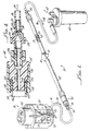
- FIG. 1 an apparatus 10 for sodding harvested microvessel cells onto the inner lumenal surface of an elongate tubular synthetic vascular graft 12 is depicted.
- the graft 12 (only a small portion of which is visible in Figure 1) is disposed within a similarly elongate tubular sodding tube 14.
- the apparatus 10 is connected by a flexible conduit 16 to a processing vessel assembly 18.
- This processing vessel assembly 18 includes a processing vessel 20, and a holder 22 for the processing vessel 20. Closer examination of the processing vessel 20 will show that it includes a chambered upper tissue digestion and separation portion, generally indicated with the numeral 24; and a lower chambered collection structure (referred to as an ampule chamber portion), and generally indicated with the numeral 26.
- microvessel endothelial cells which have been separated from endothelial or adipose cells by enzymatic digestion are concentrated by centrifuging into an elongate vertically extending passage (not seen in the drawing Figures) to form a "pellet" of such cells.
- a pair of manually-operable two-way valving members 28 and 30 are carried on the ampule portion 26.
- the upper one 28 of these two valving members respectively connects the internal passage of the ampule portion 26 at its upper end either to the digestion and separation portion 24 or to a respective luer-type fitting, which fitting is disposed on the back side of the ampule portion 26 as seen in Figure 1 and is only partially visible in this Figure.
- this top luer-type fitting is connected to a source of liquid, such as a solution of serum and/or media (not shown).
- the lower valve member 30 selectively connects the inner passage of the ampule portion 26 at a location slightly above the lower end of this passage to a luer-type fitting 32.
- the conduit 16 is connected with the fitting 32 in order to receive the pellet of centrifuged microvessel endothelial cells from the ampule portion 26.
- the sodding tube 14 includes a luer-type fitting 36, to which the conduit 16 is also connected.
- the conduit 16 at each end includes a male luer-type fitting 38 with a freely-rotational collar portion so that the conduit 16 may be connected with the fittings 32 and 36 without twisting of this conduit or relative rotation of either of the assembly 18 or of tube 14. This feature provides a considerable convenience and ease of handling of the apparatus 10 under operating room conditions.
- the sodding tube 14 includes an inlet and filter pack portion, generally indicated with the numeral 40, an elongate sodding chamber tube portion 42, and an outlet fitting and check valve portion 44.
- Portion 44 provides fluid connection via a conduit 46, and as is indicated by arrow 48, for fluid flow from the graft 12 within tube portion 42 to a liquid catch receptacle 50.
- Receptacle 50 may be connected to a source of vacuum, as is indicated by arrow 52.
- the sodding tube chamber portion 42 of sodding tube 14 includes an elongate semi-rigid and shape-retaining tubular member 54, which cooperates with the inlet fitting portion and with outlet fitting portion 44 to define a sodding chamber 56. Graft 12 is extended along the length of chamber 56, as will be more fully explained below. Adjacent to each end, the sodding tube member 54 defines a radially outwardly opening groove, both of which are referenced with the numeral 58. Both ends of the sodding tube member 54 are the same so that this tubular member is reversible and the sodding tube 14 may be assembled without concern for which end of the tube 42 is assembled with the inlet or outlet end fittings. An O-type sealing ring member 60 is received into each groove 58.
- the inlet and filter pack fitting portion 40 includes an elongate tubular body 62 defining ah axially extending stepped through bore 64.
- a smaller diameter portion 66 of bore 64 opens axially on a dual-size hose barb 68.
- Barb 68 outwardly has a first section 68', upon which graft 12 is received, which is sized to sealingly receive such a 4 mm. graft.
- a second and outwardly larger diameter section 68" of the barb 68 may sealingly receive a 5 mm. graft (not shown).
- An elastic ring 69 is received on the barb 68 and around the proximal end portion of graft 12. This elastic ring 69 is similar to an O-ring, and may be slid along the graft onto the barb 68, subsequently to be rolled along the barb 68 to secure either size of graft on this barb.
- a larger diameter portion 70 of the stepped bore 64 receives a filter pack assembly, which is generally referenced with the numeral 72.
- the filter pack assembly 72 includes four disk-like screen filter members, respectively referenced with the numerals 74a, 74b, 74c, and 74d. These screen filter members 74 a-d are successively of finer mesh toward the sodding chamber 56, and are spaced apart from one another by intervening tubular spacer sleeve members 76a, 76b, and 76c.
- the filter member 74a is a square weave of 0.4064 mm (0.0160 inch) stainless steel wire, with a mesh of 20x20 wires, providing openings of substantially 21.9 mm 2 (0.0340 inch square), with an open area of 46.2 percent.
- the filter member 74b is a square weave of 0.22 mm (0.0085 inch) stainless steel wire, with a mesh of 40x40 wires, providing openings of substantially 10.65 mm 2 (0.0165 inch square), with an open area of 43.6 percent.
- Filter member 74c is preferably a square weave of 0.09 mm (0.0035 inch) stainless steel wire, with a mesh of 88x88 wires, providing openings of substantially 5.1 mm 2 (0.0079 inch square), with an open area of 47.9 percent.
- filter member 74d is preferably a square weave of 0.028 mm (0.0011 inch) stainless steel wire, with a mesh of 325x325 wires, providing openings of substantially 1.3 mm 2 (0.0020 inch square), with an open area of 41.6 percent. Consequently, it is apparent that cell aggregations larger than the openings of the filter member 74d cannot pass to the graft 12.
- each filter member 74a-d is similar, and the fluid flow resistance of these filter members is also similar. Consequently, a selected and controlled level of turbulence is achieved both upstream and downstream of each of the filter members 74a-d.
- the stainless steel wire of the screens 74a-d is preferably coated with parylene in order to lower the surface energy of the surface exposed to the viable cells.
- screen or mesh material of appropriate filament size to provide the necessary opening sizes and open areas, and formed of polymer material which has sufficient mechanical strength to sustain the pressure differential across these filter members may be used in the filter pack assembly 72.
- the screen filter member 74d rests upon a step 78 on bore 64, while the screen member 74a is engaged by a closure member 80 defining a recess 82 confronting the screen member 74a. Consequently, a series of chambers 84a, 84b, 84c, 84d, and 84e each successively closer to the sodding chamber 56 are defined within the tubular body 62.
- This tubular body 62 outwardly defines a thread portion 86 upon which a tubular nut member 88 is threadably engageable.
- This nut member 88 traps an O-ring type sealing member 90, while the closure member 80 includes a cylindrical portion 92 upon which a groove 94 is defined.
- An O-ring type of sealing member 96 is received into the groove 94, and sealingly cooperates with the inner surface of the tubular body 62.
- redundant sealing is provided at the interface of the closure member 80 and tubular body 62 to assure that blood products are not lost into the environment where surgical and laboratory personnel are working with the apparatus 10.
- the luer fitting 36 is threadably received at an end of a stepped through bore 98, a larger diameter portion of which defines the recess 82.
- the body 62 In order to secure the tubular body 62 sealingly to the sodding chamber tubular member 54, the body 62 outwardly defines a thread portion 100 leading to a cylindrical portion 102.
- the cylindrical portion 102 is sized to fit closely within the tubular member 54.
- a nut member 104 is threadably received upon the thread portion 100, and defines a stepped bore 106.
- the O-ring member 60 is trapped in a portion 108 of the bore 106 when the nut member 104 is threadably engaged with thread portion 100 with the cylindrical portion 102 inserted into the tubular member 54, viewing Figure 3.
- the graft 12 is disposed within and along the length of the tubular member 54.
- One end of the graft is sealingly secured to the dual-size barb 68.
- a portion of the tubular member 54 is broken away in Figure 1 solely for purposes of illustration to reveal that a proximal end of the graft 12 is closed by a barbed and dual-size plug member 110.
- an elastic ring 69 secures the plug member 110 in the distal end portion of graft 12.
- the outlet and check valve fitting portion 44 includes a tubular body 112. Similarly to the tubular body 62, this body 112, includes a cylindrical portion 114 sized to fit within the tubular body 54, and a thread portion 116. A nut member 118 threadably engages the thread portion 116 and forces the O-ring 60 sealingly into a portion 120 of a stepped bore 122 of this nut member 118.
- the tubular member 112 defines a through bore 124, an outer portion of which is threaded.
- a male luer-type fitting 126 is threadably and sealingly received into the bore 124, and provides for a check valve assembly 128 to be connected with the bore 124.
- This check valve assembly 128 includes a tubular body 130 defining a stepped through bore 132.
- the bore 132 terminates in a hose barb portion 134 to which the conduit 46 is connected.
- a resilient polymeric duck-bill type valve body 136 Within bore 132 is sealingly disposed a resilient polymeric duck-bill type valve body 136.
- This valve body 136 includes a pair of mutually engaging and cooperating pressure-responsive lips or "duck bill” portions 138 which sealingly cooperate with one another to prevent fluid flow from conduit 46 toward chamber 56, but which will yieldably disengage from one another to allow fluid flow in the opposite direction.
- adipose or fat tissue which is rich in microvessel cells, is harvested from a patient who is to receive a synthetic vascular graft. This harvesting may preferably be conducted by use of a liposuction apparatus (not shown). Most preferably, the tissue harvesting may be conducted using an apparatus as disclosed in copending United States patent application US-A-5 744 360.
- the harvested fat tissue immediately from the body and while still warm is injected via a port on the top of the process vessel 20 into a chamber defined within the upper portion 24 of the process vessel so that this tissue resides within a screen basket assembly (not shown) held within this vessel.
- the harvested fat tissue is then rinsed with sterile liquid to remove most of the connective tissue and blood cells which have been collected by the liposuction process.
- an enzymatic digesting material such as collagenase, which is also warmed to body temperature is introduced into the upper chamber of portion 24.
- the process vessel 20, which is already in its holder 22, is placed into a protective outer canister (not shown), and this canister is closed with a lid (also not shown).
- This process vessel assembly with the rinsed fat tissues and enzymatic digestion material is placed into a warm air oven upon an agitation plate.
- the warm air oven serves to preserve the tissues at about body temperature, and to facilitate digestion with the enzymatic material to free the microvessel cells. This digestion and freeing of the microvessel cells is assisted by agitation.
- the process vessel assembly 18 is transferred to a centrifuge.
- the holder 22 and closed canister serve to prevent spilling of the contents of the process vessel 20, and to protect medical personnel from contact with patient tissues and body fluids.
- this process is carried out in accord with the teaching of copending United States patent application US-A-5 744 360, identified above.
- the centrifuge is operated at about 700 Gs for a time sufficient to separate the freed microvessel cells from the fat cells in the chamber within upper portion 24.
- the valving members 28 and 30 are in the positions necessary to communicate the upper chamber of the process vessel 20 with the ampule chamber within lower portion 26. Consequently, a "pellet" of microvessel cells is formed in the ampule chamber portion 26. A small residue of packed red blood cells and other solid debris may be formed in the very bottom of the ampule chamber portion 26.
- the vessel 20 in its holder 22 is removed from the canister (not shown), and placed in association with the sodding tube 14 containing the synthetic graft 12 which the patient is to receive.
- This sodding tube 14 may preferably be supplied as a sterile assembly including the graft 12 already in sodding chamber 56.
- the sterile sodding tube and graft are removed from their sterile shipping package immediately prior to connection of the conduits 16 and 46 in order to assist in best preserving aseptic conditions for the sodding process.
- a source of sterile buffered liquid at about body temperature is connected to the luer fitting associated with valve member 28.
- This source of liquid may be elevated somewhat to assist in the necessary liquid flow.
- the valve member 28 is moved to the position communicating the liquid into the upper end of the ampule chamber portion 26, which simultaneously separates the ampule portion 26 from the processing chamber portion 24.
- the luer fitting 32 is connected to the sodding tube 14 by conduit 16, and the valve member 30 is manually turned to the position communicating the ampule chamber portion with the fitting 32.
- valve member 30 in this way also separates the small quantity of packed red-blood cells and other debris which collects in the bottom of the passage of the ampule chamber portion 26 from communication with luer fitting 32. Additionally, the sodding tube 14 is evacuated so that a partial vacuum assists in pulling liquid from the source through the ampule chamber portion 26, through the conduit 16, through the filter pack portion 40, and into the inner lumen of the graft 12. As described above, the liquid is then forced to flow through the porous wall of the graft 12 so that the microvessel endothelial cells are deposited onto and into the porous surface of this graft 12.
- Aggregations of cells which are small enough to pass through the filter 74a may or may not pass through filter 74b, and so on with the following filters 74c and 74d. Aggregations of cells which are not small enough to pass through a particular filter will be exposed to the turbulence and a gentle "buffeting" because of the selected level of fluid flow maintained in the chambers 84a-e. The level of turbulence and fluid flow is balanced so that cells are not excessively damaged by impacts with the filter members, and are not lodged into the interstices of the filter members 74a-d.
- each chamber 84a-d are successively broken up into progressively smaller aggregations, freeing individual cells and smaller aggregations with each successive break up of larger aggregations.
- the check valve assembly 128 prevents any possible reflux of liquid which could interfere with sodding of cells onto the surface of the graft 12.
- Construction and testing of actual apparatus 10 for sodding harvested microvessel cells, and use of this apparatus to sod cells onto the inner lumenal surface of grafts 12 in accord with the present invention has shown a remarkable improvement in the yield of microvessel cells per gram of fat tissue processed. Consequently, the reduction in thrombogenicity of a synthetic graft which can be effected by lining the graft with microvessel cells from the patient can be improved by use of the present invention. Also, the efficacious number of microvessel cells necessary to treat a synthetic graft may be obtained with a smaller extraction of adipose tissue from the patient.
- Figures 5-7 provide representations of microphotographs of microvessel cells sodded onto the inner lumenal surface of a graft at three locations along the length of the graft, as is evidenced by photographs of the stained cell nucleus (indicated with the representative reference numeral 140) taken while the stained cells were illuminated with ultraviolet light. These depictions of the microphotographs indicate that a more than adequate level of cell sodding is present on the inner lumenal surface of the graft 12.
- Figure 5 is a depiction of an area of the graft slightly distally of the barb 68.
- Figure 6 is taken at mid-length of the graft 12.
- Figure 7 represents a microphotograph taken just proximally of the plug member 110, recalling Figure 1.
- FIGS. 1-10 illustrate the uniform distribution of the isolated cells on the inner surface of the graft 12.
- all or a selected portion of the graft 12 may be surgically implanted with the graft providing a low thrombogenicity because of the sodded cells on the inner lumenal surface of this graft.
Landscapes
- Health & Medical Sciences (AREA)
- General Health & Medical Sciences (AREA)
- Biomedical Technology (AREA)
- Animal Behavior & Ethology (AREA)
- Public Health (AREA)
- Oral & Maxillofacial Surgery (AREA)
- Transplantation (AREA)
- Veterinary Medicine (AREA)
- Life Sciences & Earth Sciences (AREA)
- Vascular Medicine (AREA)
- Engineering & Computer Science (AREA)
- Chemical & Material Sciences (AREA)
- Epidemiology (AREA)
- Medicinal Chemistry (AREA)
- Dermatology (AREA)
- Gastroenterology & Hepatology (AREA)
- Pulmonology (AREA)
- Cardiology (AREA)
- Heart & Thoracic Surgery (AREA)
- Prostheses (AREA)
- Apparatus Associated With Microorganisms And Enzymes (AREA)
Description
Claims (18)
- A sodding tube assembly (10) for use in receiving a quantity of certain isolated cells from tissues and for sodding the cells onto an inner lumenal surface of a tubular synthetic graft (12) having a porous wall, said sodding tube assembly comprising:an elongate tubular member (14) having a pair of opposite ends, characterized in that said assembly further comprises:an inlet fitting and filter pack assembly (40) sealingly cooperating with said tubular member (14) at one of said pair of opposite ends, said inlet and filter pack assembly (40) defining an inlet flow path for receiving the cells in liquid and communicating the cells and liquid together into the lumen of the graft, and a plurality of filter members (74a,74b,74c,74d) cooperatively defining a number of turbulent-flow chambers (84a,84b,84c,84d,84e) successively along said inlet flow path;an outlet fitting and check valve assembly (44) sealingly cooperating with said tubular member (14) at the other of said pair of opposite ends and cooperating with said tubular member (14) and said inlet and filter pack assembly (40) to define a sodding chamber (56) within which said graft is disposed to receive the cells and liquid from said inlet and filter pack assembly into the lumen of the graft (12) and to flow the liquid outwardly through said porous wall of the graft (12) to said sodding chamber (56), said outlet fitting and check valve assembly (44) defining an outlet flow path leading from said sodding chamber to an outlet from said sodding tube assembly (10), and including a check valve device (136) disposed in said outlet flow path for preventing reflux of liquid along said flow path from said outlet toward said sodding chamber.
- The sodding tube assembly of Claim 1 wherein said inlet and filter pack assembly (40) defines four turbulent-flow chambers (84a,84b,84c,84d,84e) each preceding a respective one of said filter members (74a,74b,74c,74d).
- The sodding tube assembly (10) of Claim 1 or 2 wherein said pair of opposite ends of said elongate tubular member (14) are substantially identical with one another.
- The sodding tube assembly of Claim 1 2 or 3 wherein said inlet fitting and filter pack assembly (40) includes a tubular body (62) defining a stepped through bore (98); said tubular body (62) including a cylindrical portion receivable into one of said pair of opposite ends of said tubular member (14); a sealing member (60) disposed in sealing relation with said tubular body and said elongate tubular member, a nut member (106) engaging said inlet fitting and filter pack assembly (40) and sealingly securing said tubular body (62) thereto, said tubular body (62) defining a barb member (68',68") extending therefrom into said tubular member (14) for receiving thereon the synthetic graft (12); and said tubular body (62) defining a stepped through bore opening at one end on said barb (68',68") and defining said inlet flow path and receiving said plurality of filter members (74a,74b,74c,74d) for defining said plurality of turbulent-flow chambers (84a,84b,84e,84d,84e) along said inlet flow path.
- The sodding tube assembly (10) of Claim 4 wherein said tubular body (62) further includes a closure member (80) closing an end of said stepped through bore remote from said tubular member, said closure member (80) defining a recess (82) confronting a first of said plurality of filter members (74a,74b,74c,74d) and defining a first one of said plurality of turbulent-flow chambers (84a,84b,84c,84d,84e).
- The sodding tube assembly (10) of any preceding Claim wherein said check valve (136) of said outlet fitting and check valve assembly (44) includes a check valve member (136) disposed in said flow path which includes a pair of pressure-responsive lips (138) sealingly cooperating to prevent liquid reflux along said flow path from said outlet toward said sodding chamber (56), said pair of lips (138) disengaging from one another to allow liquid flow from said sodding chamber (56) toward said outlet.
- A sodding tube assembly (10) for use in receiving a quantity of isolated cells from tissues and for sodding the cells onto an inner lumenal surface of a tubular synthetic graft (12) having a porous wall, said sodding tube assembly (10) comprising:an elongate tubular member (14) having a pair of opposite ends which are substantially identical with one another, characterized in that the said sodding tube assembly further comprises:an inlet fitting and filter pack assembly (40) sealingly cooperating with said tubular member (14) at one of said pair of opposite ends, said inlet and filter pack assembly (40) defining an inlet flow path for receiving the quantity of cells in liquid and communicating the cells and liquid together into the lumen of the graft, said inlet fitting and filter pack assembly (40) including a tubular body (62) defining a stepped through bore; said tubular body (62) including a cylindrical portion (68) receivable into one of said pair of opposite ends of said tubular member (14); a sealing member (60) sealingly cooperating with said cylindrical body and with said tubular member (14); and nut member (104) engaging said tubular body to secure the latter to said tubular member (54); said tubular body (62) defining a barb member (68) extending therefrom into said tubular member (54) for receiving thereon a proximal end portion of the synthetic graft (12); and said tubular body (62) defining a stepped through bore opening at one end on said barb and defining a respective part of said inlet flow path and receiving a plurality filter members (74a-d) spaced apart to cooperatively define a number of turbulent-flow chambers (84a-e); said tubular body (14) further including a closure member (80) closing an end of said stepped through bore remote from said tubular member, said closure member (80) defining a recess confronting a first one of said plurality of filter members (74a-d) and defining a first of said plurality of turbulent-flow chambers (84a-e);an outlet fitting and check valve assembly (44) sealingly cooperating with said tubular member (14) at the other of said pair of opposite ends, said inlet and filter pack assembly (40) and said outlet and check valve assembly (44) cooperating with said tubular member to define a sodding chamber (56) within which the graft (12) is disposed to receive the cells and liquid from said inlet and filter pack assembly (40) into the lumen of the graft (12) and to flow the liquid outwardly through the porous wall of the graft (12) to said sodding chamber (56), said outlet fitting and check valve assembly (44) defining an outlet flow path leading from said sodding chamber (56) to an outlet from said sodding tube assembly, and including a check valve member (136) disposed in said outlet flow path, said check valve member (136) including a pair of pressure-responsive lips (138) sealingly cooperating to prevent liquid reflux along said flow path from said outlet toward said sodding chamber (56), and said pair of lips (138) disengaging from one another to allow liquid flow from said sodding chamber toward said outlet.
- The sodding tube assembly (10) of Claim 7 wherein said inlet and check valve assembly (40) defines four turbulent-flow chambers (84a-e) separated from one another by respective ones of said plurality of filter members (74a-d).
- The sodding tube assembly (10) of any preceding Claim wherein each of said plurality of filter members (74a-d) defines substantially the same open area.
- The sodding tube assembly (10) of any one of Claims 1 to 7 wherein said plurality of respective filter members (74a-d) are of progressively finer opening size along said inlet flow path toward said sodding chamber (56).
- The sodding tube assembly (10) of any preceding Claim wherein at least one of said plurality of filter members (74a-d) is formed of polymer material.
- The sodding tube assembly (10) of any preceding Claim wherein said plurality of filter members includes four filter members (74a-d), a first of said filter members being formed of a square weave of 0.4064 mm (0.0160 inch) wire, with a mesh of 20x20 wires, providing openings of substantially 21.9 mm2 (0.0340 inch square), with an open area of 46.2 percent; a second of said filter members being formed of a square weave of 0.22 mm (0.0085 inch) wire, with a mesh of 40x40 wires, providing openings of substantially 10.65 mm2 (0.0165 inch square), with an open area of 43.6 percent; a third of said filter members being formed of a square weave of 0.09 mm (0.0035 inch) wire, with a mesh of 88x88 wires, providing openings of substantially 5.1 mm2 (0.0079 inch square), with an open area of 47.9 percent; and the forth of said filter members being formed of a square weave of 0.028 mm (0.0011 inch) wire, with a mesh of 325x325 wires, providing openings of substantially 1.3 mm2 (0.0020 inch square), with an open area of 41.6 percent.
- The sodding tube assembly (10) of Claim 12 wherein said wires are formed of stainless steel.
- The sodding tube assembly (10) of Claim 12 wherein said wires are coated with a material selected to reduce the surface energy of said wires.
- The sodding tube assembly (10) of Claim 14 wherein said wires are coated with parylene.
- The sodding tube assembly of any preceding Claim wherein said inlet and filter pack assembly (40) further includes a plurality of spacer sleeve members (76a-c) interposed individually between adjacent ones of said plurality of filter members (74a-d).
- The sodding tube assembly (10) of any preceding Claim further including a conduit (16) for connecting a source of the isolated cells from tissues with said sodding tube assembly (10), said conduit (16) at each end thereof including a male luer-type connector (38) with a freely rotational fastening collar, and said sodding tube assembly including a female luer-type connector carried upon said inlet fitting and filter pack assembly (40) and communicating with said inlet flow path for receiving the quantity of cells in liquid and communicating the cells and liquid together into the lumen of the graft (12).
- A method of sodding cells onto the inner lumenal surface of an elongate tubular vascular graft (12) having a porous wall, said method comprising the steps of:characterized by the further steps of:providing an elongate tubular shape-retaining body (14) defining a flow path extending there along and an elongate sodding chamber (56) therewithin;disposing the graft (12) within and along said sodding chamber (56);plugging a distal end of the graft (12);providing a pellet of aggregated cells;flushing said pellet of aggregated cells into said elongate tubular body (14) with a flow of liquid;successively and repeatedly subjecting said pellet of aggregated cells to a controlled level of liquid turbulence to break up said aggregation into individual cells and progressively smaller aggregations, while simultaneously subjecting said cell aggregations to a series of successively finer filtrations to prevent aggregations of cells above a determined size from reaching said graft and sodding chamber (56);introducing the liquid and individual cells along with aggregations of cells below said determined-size into the lumen of the tubular vascular graft; andflowing said fluid through the porous wall of the graft while sodding the individual cells and aggregations below said determined size onto the inner lumenal surface of the graft (12).
Applications Claiming Priority (3)
| Application Number | Priority Date | Filing Date | Title |
|---|---|---|---|
| US08/386,048 US5804366A (en) | 1995-02-09 | 1995-02-09 | Method and apparatus for sodding microvessel cells onto a synthetic vascular graft |
| US386048 | 1995-02-09 | ||
| PCT/US1996/001367 WO1996024307A1 (en) | 1995-02-09 | 1996-02-01 | Method and apparatus for sodding microvessel cells onto a synthetic vascular graft |
Publications (2)
| Publication Number | Publication Date |
|---|---|
| EP0808141A1 EP0808141A1 (en) | 1997-11-26 |
| EP0808141B1 true EP0808141B1 (en) | 2003-05-02 |
Family
ID=23523938
Family Applications (1)
| Application Number | Title | Priority Date | Filing Date |
|---|---|---|---|
| EP96907860A Expired - Lifetime EP0808141B1 (en) | 1995-02-09 | 1996-02-01 | Method and apparatus for sodding microvessel cells onto a synthetic vascular graft |
Country Status (6)
| Country | Link |
|---|---|
| US (1) | US5804366A (en) |
| EP (1) | EP0808141B1 (en) |
| JP (1) | JP3693676B2 (en) |
| CA (1) | CA2208356A1 (en) |
| DE (1) | DE69627823T2 (en) |
| WO (1) | WO1996024307A1 (en) |
Families Citing this family (42)
| Publication number | Priority date | Publication date | Assignee | Title |
|---|---|---|---|---|
| US7550005B2 (en) | 1995-06-07 | 2009-06-23 | Cook Incorporated | Coated implantable medical device |
| US20020128680A1 (en) * | 2001-01-25 | 2002-09-12 | Pavlovic Jennifer L. | Distal protection device with electrospun polymer fiber matrix |
| US7794408B2 (en) | 2003-03-28 | 2010-09-14 | Ethicon, Inc. | Tissue collection device and methods |
| US7611473B2 (en) | 2003-09-11 | 2009-11-03 | Ethicon, Inc. | Tissue extraction and maceration device |
| US8034003B2 (en) | 2003-09-11 | 2011-10-11 | Depuy Mitek, Inc. | Tissue extraction and collection device |
| US9581942B1 (en) | 2005-03-23 | 2017-02-28 | Shippert Enterprises, Llc | Tissue transfer method and apparatus |
| US8062286B2 (en) * | 2005-03-23 | 2011-11-22 | Shippert Ronald D | Tissue transplantation method and apparatus |
| US7789872B2 (en) * | 2005-03-23 | 2010-09-07 | Shippert Ronald D | Tissue transplantation method and apparatus |
| US7780649B2 (en) | 2005-03-23 | 2010-08-24 | Shippert Ronald D | Tissue transplantation method and apparatus |
| US8622997B2 (en) | 2005-03-23 | 2014-01-07 | Ronald D. Shippert | Tissue transfer method and apparatus |
| US7794449B2 (en) * | 2005-03-23 | 2010-09-14 | Shippert Ronald D | Tissue transplantation method and apparatus |
| EP1888238B1 (en) * | 2005-04-21 | 2014-08-13 | California Institute of Technology | Parylene membrane filters |
| US7846743B2 (en) * | 2005-04-21 | 2010-12-07 | California Institute Of Technology | Uses of parylene membrane filters |
| US7846393B2 (en) * | 2005-04-21 | 2010-12-07 | California Institute Of Technology | Membrane filter for capturing circulating tumor cells |
| US7622298B2 (en) * | 2006-03-24 | 2009-11-24 | Norits, Inc. | Method for creating perfusable microvessel systems |
| US8445280B2 (en) * | 2006-03-24 | 2013-05-21 | Nortis, Inc. | Method for creating perfusable microvessel systems |
| US8003388B2 (en) * | 2006-03-24 | 2011-08-23 | Nortis, Inc. | Method for creating perfusable microvessel systems |
| AU2008232516B2 (en) * | 2007-03-30 | 2013-08-22 | Smith & Nephew, Inc. | Tissue harvesting |
| US20100112696A1 (en) * | 2008-11-03 | 2010-05-06 | Baxter International Inc. | Apparatus And Methods For Processing Tissue To Release Cells |
| US8309343B2 (en) | 2008-12-01 | 2012-11-13 | Baxter International Inc. | Apparatus and method for processing biological material |
| US8770047B2 (en) * | 2009-07-27 | 2014-07-08 | The Thailand Research Fund | Apparatus and method for particle analysis |
| US10130736B1 (en) | 2010-05-14 | 2018-11-20 | Musculoskeletal Transplant Foundation | Tissue-derived tissuegenic implants, and methods of fabricating and using same |
| US9352003B1 (en) | 2010-05-14 | 2016-05-31 | Musculoskeletal Transplant Foundation | Tissue-derived tissuegenic implants, and methods of fabricating and using same |
| US8883210B1 (en) | 2010-05-14 | 2014-11-11 | Musculoskeletal Transplant Foundation | Tissue-derived tissuegenic implants, and methods of fabricating and using same |
| IT1400069B1 (en) | 2010-05-20 | 2013-05-17 | Tremolada | DEVICE AND METHOD FOR THE PREPARATION OF FABRIC, IN PARTICULAR ADIPOUS FABRIC FOR TRANSPLANTATION OBTAINED FROM ADIPOUS LOBULAR MATERIAL EXTRACTED THROUGH LIPOSUCTION |
| US8887770B1 (en) | 2011-03-17 | 2014-11-18 | Ronald D. Shippert | Vessel fill control method and apparatus |
| US8834928B1 (en) | 2011-05-16 | 2014-09-16 | Musculoskeletal Transplant Foundation | Tissue-derived tissugenic implants, and methods of fabricating and using same |
| US9468709B2 (en) | 2012-11-12 | 2016-10-18 | Shippert Enterprises, Llc | Syringe fill method and apparatus |
| WO2015017500A1 (en) | 2013-07-30 | 2015-02-05 | Musculoskeletal Transplant Foundation | Acellular soft tissue-derived matrices and methods for preparing same |
| US10772997B2 (en) | 2014-05-15 | 2020-09-15 | Ronald D. Shippert | Tissue parcelization method and apparatus |
| US10927347B2 (en) * | 2015-05-15 | 2021-02-23 | Black Tie Medical Inc. | Device and method for breaking down and sizing harvested fat |
| CA2986702C (en) | 2015-05-21 | 2023-04-04 | David Wang | Modified demineralized cortical bone fibers |
| US10912864B2 (en) | 2015-07-24 | 2021-02-09 | Musculoskeletal Transplant Foundation | Acellular soft tissue-derived matrices and methods for preparing same |
| US11052175B2 (en) | 2015-08-19 | 2021-07-06 | Musculoskeletal Transplant Foundation | Cartilage-derived implants and methods of making and using same |
| ITUB20154668A1 (en) * | 2015-10-14 | 2017-04-14 | Mario Goisis | DEVICE FOR FILTRATION OF GREASE EXTRACTED WITH LIPOSUCTION SURGICAL PROCEDURES |
| US10702629B2 (en) | 2016-05-13 | 2020-07-07 | Black Tie Medical Inc. | Conditioning harvested fat for re-injection |
| WO2020023580A1 (en) * | 2018-07-24 | 2020-01-30 | Khalaj Ben M | Device amd method for resizing adipose and other tissues for implantation |
| KR102202861B1 (en) * | 2019-04-09 | 2021-01-18 | 이준석 | Apparatus for changing screen, system for reducing size of biological tissue comprising the same, method of using the same and method of separating target material from biological tissue associated therewith |
| RU2731512C1 (en) * | 2019-08-12 | 2020-09-03 | Игорь Юрьевич Попов | Device for grinding lipoaspyrate |
| RU194959U1 (en) * | 2019-08-30 | 2020-01-09 | Игорь Юрьевич Попов | DEVICE FOR GRINDING LIPOASPIRATE |
| US20240227001A9 (en) * | 2022-10-24 | 2024-07-11 | Entegris, Inc. | High pressure filter apparatus and related methods |
| WO2026112716A1 (en) * | 2024-11-28 | 2026-06-04 | Silimed - Indústria De Implantes Ltda | Adipose tissue fluidification device |
Family Cites Families (17)
| Publication number | Priority date | Publication date | Assignee | Title |
|---|---|---|---|---|
| USRE19298E (en) * | 1934-08-28 | Filter | ||
| US3941317A (en) * | 1973-10-26 | 1976-03-02 | Lnih, Inc. | Method and apparatus for tissue disaggregation |
| US4350768A (en) * | 1980-09-19 | 1982-09-21 | Bristol Myers Company | Method for preparing single cell suspension |
| US5441539A (en) * | 1985-06-06 | 1995-08-15 | Thomas Jefferson University | Endothelial cell deposition device |
| US5372945A (en) * | 1985-06-06 | 1994-12-13 | Alchas; Paul G. | Device and method for collecting and processing fat tissue and procuring microvessel endothelial cells to produce endothelial cell product |
| US4820626A (en) * | 1985-06-06 | 1989-04-11 | Thomas Jefferson University | Method of treating a synthetic or naturally occuring surface with microvascular endothelial cells, and the treated surface itself |
| US5035708A (en) * | 1985-06-06 | 1991-07-30 | Thomas Jefferson University | Endothelial cell procurement and deposition kit |
| US4990131A (en) * | 1987-09-01 | 1991-02-05 | Herbert Dardik | Tubular prostheses for vascular reconstructive surgery and process for preparing same |
| US4883755A (en) * | 1987-10-28 | 1989-11-28 | Thomas Jefferson University | Method of reendothelializing vascular linings |
| JP2678945B2 (en) * | 1989-04-17 | 1997-11-19 | 有限会社ナイセム | Artificial blood vessel, method for producing the same, and substrate for artificial blood vessel |
| EP0446450B1 (en) * | 1990-02-09 | 1995-03-29 | Thomas Jefferson University | Device for collecting and processing fat tissue to produce endothelial cell product |
| US5356814A (en) * | 1992-09-29 | 1994-10-18 | Hoffmann-La Roche Inc. | Disaggregation device for cytological specimens |
| EP0636184B1 (en) * | 1993-01-15 | 2000-08-30 | Baxter International Inc. | Media for isolation and stabilization of cells |
| US5364790A (en) * | 1993-02-16 | 1994-11-15 | The Perkin-Elmer Corporation | In situ PCR amplification system |
| US5380589A (en) * | 1993-04-19 | 1995-01-10 | Wisconsin Alumni Research Foundation | Biotextured surfaces |
| US5409833A (en) * | 1993-07-01 | 1995-04-25 | Baxter International Inc. | Microvessel cell isolation apparatus |
| US5390859A (en) * | 1993-10-06 | 1995-02-21 | Cornell Research Foundation, Inc. | Low pressure, shear-type cell homogenizer and method of using |
-
1995
- 1995-02-09 US US08/386,048 patent/US5804366A/en not_active Expired - Fee Related
-
1996
- 1996-02-01 JP JP52432696A patent/JP3693676B2/en not_active Expired - Fee Related
- 1996-02-01 DE DE69627823T patent/DE69627823T2/en not_active Expired - Fee Related
- 1996-02-01 CA CA002208356A patent/CA2208356A1/en not_active Abandoned
- 1996-02-01 WO PCT/US1996/001367 patent/WO1996024307A1/en not_active Ceased
- 1996-02-01 EP EP96907860A patent/EP0808141B1/en not_active Expired - Lifetime
Also Published As
| Publication number | Publication date |
|---|---|
| DE69627823D1 (en) | 2003-06-05 |
| JPH10513094A (en) | 1998-12-15 |
| US5804366A (en) | 1998-09-08 |
| DE69627823T2 (en) | 2004-03-11 |
| WO1996024307A1 (en) | 1996-08-15 |
| JP3693676B2 (en) | 2005-09-07 |
| EP0808141A1 (en) | 1997-11-26 |
| CA2208356A1 (en) | 1996-08-15 |
Similar Documents
| Publication | Publication Date | Title |
|---|---|---|
| US5804366A (en) | Method and apparatus for sodding microvessel cells onto a synthetic vascular graft | |
| EP0984060B1 (en) | Microvessel cell isolation method and apparatus | |
| DE69001275T2 (en) | Set for the production and separation of endothelial cells. | |
| EP0446450B1 (en) | Device for collecting and processing fat tissue to produce endothelial cell product | |
| US5312380A (en) | Endothelial cell procurement and deposition kit | |
| AU663705B2 (en) | Device and method for collecting and processing fat tissue and procuring microvessel endothelial cells | |
| EP0830099B1 (en) | Apparatus and methods for cell isolation and collection | |
| JP5960689B2 (en) | Apparatus and method for preparing tissue for transplantation, in particular adipose tissue, from leaflet fat extracted by liposuction | |
| JP4318894B2 (en) | Cell separation device and cell separation method | |
| US5441539A (en) | Endothelial cell deposition device | |
| JPH10505513A (en) | Method for collecting adipose tissue containing autologous microvascular endothelial cells | |
| JPH07509369A (en) | Apparatus and method for processing adipose tissue to produce endothelial cell products | |
| EP3782662A1 (en) | Device for harvesting, processing, and transferring adipose tissue | |
| AU649238B2 (en) | Endothlial cell deposition device | |
| JP2003235542A (en) | Filter device |
Legal Events
| Date | Code | Title | Description |
|---|---|---|---|
| PUAI | Public reference made under article 153(3) epc to a published international application that has entered the european phase |
Free format text: ORIGINAL CODE: 0009012 |
|
| 17P | Request for examination filed |
Effective date: 19970718 |
|
| AK | Designated contracting states |
Kind code of ref document: A1 Designated state(s): CH DE FR GB IT LI |
|
| RAP1 | Party data changed (applicant data changed or rights of an application transferred) |
Owner name: EDWARDS LIFESCIENCES CORPORATION |
|
| GRAH | Despatch of communication of intention to grant a patent |
Free format text: ORIGINAL CODE: EPIDOS IGRA |
|
| GRAH | Despatch of communication of intention to grant a patent |
Free format text: ORIGINAL CODE: EPIDOS IGRA |
|
| GRAA | (expected) grant |
Free format text: ORIGINAL CODE: 0009210 |
|
| AK | Designated contracting states |
Designated state(s): CH DE FR GB IT LI |
|
| PG25 | Lapsed in a contracting state [announced via postgrant information from national office to epo] |
Ref country code: IT Free format text: LAPSE BECAUSE OF FAILURE TO SUBMIT A TRANSLATION OF THE DESCRIPTION OR TO PAY THE FEE WITHIN THE PRESCRIBED TIME-LIMIT;WARNING: LAPSES OF ITALIAN PATENTS WITH EFFECTIVE DATE BEFORE 2007 MAY HAVE OCCURRED AT ANY TIME BEFORE 2007. THE CORRECT EFFECTIVE DATE MAY BE DIFFERENT FROM THE ONE RECORDED. Effective date: 20030502 |
|
| REG | Reference to a national code |
Ref country code: GB Ref legal event code: FG4D |
|
| REG | Reference to a national code |
Ref country code: CH Ref legal event code: EP |
|
| REG | Reference to a national code |
Ref country code: CH Ref legal event code: NV Representative=s name: KELLER & PARTNER PATENTANWAELTE AG |
|
| REF | Corresponds to: |
Ref document number: 69627823 Country of ref document: DE Date of ref document: 20030605 Kind code of ref document: P |
|
| ET | Fr: translation filed | ||
| PLBE | No opposition filed within time limit |
Free format text: ORIGINAL CODE: 0009261 |
|
| STAA | Information on the status of an ep patent application or granted ep patent |
Free format text: STATUS: NO OPPOSITION FILED WITHIN TIME LIMIT |
|
| 26N | No opposition filed |
Effective date: 20040203 |
|
| PGFP | Annual fee paid to national office [announced via postgrant information from national office to epo] |
Ref country code: GB Payment date: 20050126 Year of fee payment: 10 |
|
| PGFP | Annual fee paid to national office [announced via postgrant information from national office to epo] |
Ref country code: FR Payment date: 20050217 Year of fee payment: 10 |
|
| PGFP | Annual fee paid to national office [announced via postgrant information from national office to epo] |
Ref country code: CH Payment date: 20050221 Year of fee payment: 10 |
|
| PGFP | Annual fee paid to national office [announced via postgrant information from national office to epo] |
Ref country code: DE Payment date: 20050331 Year of fee payment: 10 |
|
| PG25 | Lapsed in a contracting state [announced via postgrant information from national office to epo] |
Ref country code: GB Free format text: LAPSE BECAUSE OF NON-PAYMENT OF DUE FEES Effective date: 20060201 |
|
| PG25 | Lapsed in a contracting state [announced via postgrant information from national office to epo] |
Ref country code: LI Free format text: LAPSE BECAUSE OF NON-PAYMENT OF DUE FEES Effective date: 20060228 Ref country code: CH Free format text: LAPSE BECAUSE OF NON-PAYMENT OF DUE FEES Effective date: 20060228 |
|
| PG25 | Lapsed in a contracting state [announced via postgrant information from national office to epo] |
Ref country code: DE Free format text: LAPSE BECAUSE OF NON-PAYMENT OF DUE FEES Effective date: 20060901 |
|
| REG | Reference to a national code |
Ref country code: CH Ref legal event code: PL |
|
| GBPC | Gb: european patent ceased through non-payment of renewal fee |
Effective date: 20060201 |
|
| REG | Reference to a national code |
Ref country code: FR Ref legal event code: ST Effective date: 20061031 |
|
| PG25 | Lapsed in a contracting state [announced via postgrant information from national office to epo] |
Ref country code: FR Free format text: LAPSE BECAUSE OF NON-PAYMENT OF DUE FEES Effective date: 20060228 |